Forum sponsored by:

Myford ML1 ? or 2 ?
| Me. | 06/12/2021 08:45:35 |
| 147 forum posts 30 photos | Hi All A little bit of history... I live on an Island in the English Channel and I purchased a Myford lathe almost 2 years ago from an adjacent Island just before the 1st lock down. This was to be my first lathe and was looking forward to it arrival. Unfortunatly as things progressed through Covid times the stretch of water between the two islands proved a issue and the lathe was stuck. Along came the opportunity to purchase a Harrison 140 from the UK - the deal was done and the lathe arrived - across the same stretch of water but bypassing the smaller island.... anyway i'm getting to the point. A good friend of mine was visiting the smaller island last week and he managed to pick up the Myford and bring it back to me. I must say it is a beauty - hardly any wear apart from a few of the gears seem a little loose, the bed looks great. A good strip clean adjust and rebuild is the order of the day. Ive done lots of research on the ML1 but this seems different - all the pictures ive seen have flat drum drive pulley this one has V pulleys. The serial number is either *35* or *352* can't quite work it out as there is a little bit of denting on the plate. Are there any users of the ML1 out there that can help with directions and tips as to the overhaul - one thing i'd like to do is take out the slop in the gear train. Is it best to remake the shafts or bush the gears ?? Finally (for now) what colour would the original ML1's have been. This one is black. I will post some pictures as soon as I make a start on the overhaul. Thanks |
| Ady1 | 06/12/2021 09:42:10 |
 6137 forum posts 893 photos | Once you post some pictures you'll get more responses do the back as well as the front if you can |
| Lee Rogers | 06/12/2021 11:10:13 |
 203 forum posts | ML 1/2/3/4 identifying always throws up a few curves . The lathes.co.uk page has a very in depth feature on the entire range and it's evolution. Don't get into serial numbers they will fry your brain, the cast in numbers / letters are foundry marks and are meaningless from an id view. Other numbers on brass plates or the bed may or may not be Myford origin, company owners often put their own asset numbers on. The final curve is owner mods, details like pulleys , hand wheels etc are often found to have been changed. Don't worry about the slack changewheels , tight ones are more a problem.As a companion to your Harrison it's potentially a great little lathe if used within it's limitations of size and rigidity. Above all enjoy ! |
| Philip Rowe | 06/12/2021 12:16:56 |
| 248 forum posts 33 photos | I had a ML2 passed onto me by my father who purchased it new in 1933/4. It was originally fitted with flat belt pulleys but I later converted it to v pulleys as it suited my drive system and I was able to squeeze four diameters in the space of the original three to give a greater speed variation. This is something that I know quite a few owners have done over the years. It's serial number was L277 which was stamped into a small machined pad on the left hand side of the bed below the back gear. To the best of my knowledge Myford never used separately attached number plates and as Lee says the cast numbers will fry your brain. One thing that easily identifies a ML1 is the headstock and bed are one casting, whereas with the ML2 and onwards the headstock was a separate casting bolted to the bed. Also the ML2 had a centre height of 3 1/8" not 3 1/2" which further aids identification. As to colour my father's was originally a very dark greeny blue which by the time I had it had become almost like black. Hope some of this helps. Phil |
| Howard Lewis | 06/12/2021 12:22:20 |
| 7227 forum posts 21 photos | As I understand it the Odd numbers are something like 15" centres, and the even numbers longer Also the ML1 and ML2 were 3 .125" centre height, where the ML3 and ML4 were 3.50", like the post war ML7 Series Look at Lathes UK site for more details!. The Cross and Top Slide Leadscrews are 12 tpi, so each of the 80 graduations are not exactly a "thou At least the main Leadscrew is 8 tpi. And although the changwheels are 5/8" bore 20DP, 14.5 PA, they are driven and compounded by 3/32 pins rather than the keys used on the later 7 Series. So 7 Series wheels can be used, but will need to be drilled for the 3/32 pin to match the Driving Collars and other gears. Another peculiarity is that the handwheel for the Apron, having no Idler gear, works the reverse way to what might be expected The mandrel thread started out as 7/8 BSW (9 tpi) but changed to 7/8 x 12 tpi, and some of the later lathes, I believe went to the 1.125 x 12 tpi used on the 7 Series, but without the register On lathe that I helped refurbish, I made a 7/8 x 9 to Myford (7 Series ) adaptor so that more modern chucks can be used. There is a picture in the article in MEW 310 HTH Howard. |
| Me. | 06/12/2021 17:06:21 |
| 147 forum posts 30 photos | As always the answers are very informative and useful - I spent most of today stripping it down to clean it and inspect most parts. It has the one piece headstock/body so that I assume makes it the ML 1. Th original colour can be seen in areas that have never been seen since it was put together it is a very dark greeny grey. the gap between the bedways is painted a very bright red. The cast in serial number plate just below the spindle is defiantly 352. The change wheels are held together with the small pins. (on this is there a gear chart to aid screw cutting) There doesn't appear to be a thread dial indicator, was there one for this model or if not can someone point me in the direction on how to make one. The small dial indicator on the cross slide is worn - the dial locks into the nut by way of two punched slots, with time the slots in the brass dial have worn and no longer lock into the nut, any suggestions for a repair or is this part still available. The slop in the drive train gears is going to get on my nerves and I think I will want to make them "less sloppy", any suggestions greatfully accepted. Pictures taken and posted up soon. |
| Howard Lewis | 06/12/2021 18:02:15 |
| 7227 forum posts 21 photos | The difference between the odd and even numbers is the centre disatance. The even numbers are a greater distance between centres. You will learn a lot about the machine if you read the pages on Lathes UK website, dedicated to the Myford ML. 1,2, 3 and 4. Changewheels are driven by the 3/32" pins inserted into the driving collars, and the each gear. The drillings do not go right through, so that the pins are retained, once in place. If genuine ML1,2 ,3 or 4 gears are not available, and you are prepared to drill right through one gear, it can be used as template to drill 7 Series gears. They are the same bore, but use keyways, so drill the hole away from the keyway. See the article in MEW 310 about refurbishing a ML4, It shows how to modify a Series 7 gear.. Together with the Lathes UK website, It may answer some of your questions. Gears are compounded in the same manner by the 3/32 pins. If your machine lacks the optional tumbler reverse, you may well need to set up a two stage gear train to provide a feed towards the Headstock. The finest feed that you can obtain with standard gears will need extra gears, a 20T and another 60T. The drive is 20 : 60/ 20: 65/20: 60 on the Leadscrew.. This because the Leadscrew is Right Hand, where the later ones, (7 Series ) have a conventional Left hand Thread. The threads on the Leadscrews on the Cross and Top Slides are 12 tpi, (Not 10 tpi ) So each of the 80 divisions on the dials is not exactly a thousandth of an inch. (0.001042" ) Consequently you will need to follow the maxim of "Measure twice, cut once" HTH Howard |
| Me. | 07/12/2021 15:42:26 |
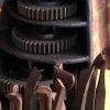
| 147 forum posts 30 photos | Some of the lathe before I totally stripped it down. Found some very interesting bits - the chuck that is fitted in the pictures is very unusual as it has a large ring that moves the jaws - it with 3 other chucks that came with the lathe are all American made. I'm not too sure what the two gears do which are fitted to the rear of the chuck - 9 oclock in the 3rd picture - other ML1's Ive seen don't have those - is it a reverse.
After these pictures were taken I finished strippijg it down for cleaning and repainting - I have decided I am going to paint it to match my Harrison 140 and my Alfred Herbert Mill.
Edited By Me. on 07/12/2021 15:50:50 |
| Richard Millington | 07/12/2021 20:03:38 |
| 101 forum posts 9 photos | The gear is for backgear, undo the V-belt drive allen screws locking it onto the headstock spindle and slide the gears in which should give backgear range. |
| Howard Lewis | 08/12/2021 08:03:45 |
| 7227 forum posts 21 photos | Your current chuck is a Scroll Chuck, operated by two tommy bars. If you decide to obtain conventional 3 and 4 jaw chucks, you will either need to make backplates for them, or alternatively make an adaptor so that the normally available chucks and backplates withr the 1.125 x 12 tpi, with 1.250 register can be used.. The adaptor will have a 7/8 x 9 (7/8 BSW ) internal thread for earlier models or the 7/8 x 12 tpi on the later ones. To improve concentricity, once the internal thread has been cut, it should mbe mounted on the mandrel, and the external machining then carried out.. I was fortunate that a friend loaned me 7/8 BSW taps for the internal thread, so only the external thread needed to be cut. If you want to make backplates from scratch, castings should be available from various suppliers, or just make up the adaptor, so that easily available backplates and chucks can be used. Your machine does not appear to incorporate the optional Tumbler Reverse, so if you wished to cut Left Hand threads, only a single stage reduction with changewheels would be required. You need a two stage gear train to traverse the Saddle towards the Headstock.. When you use Backgear, do not forget to slacken or remove the grubscrew in the belt pulley. Do NOT engage Backgear with the grubscrew tight as a means of locking the spindle to remove a stuck chuck. That risks damaging all the gears involved, which will be very difficult to source for such an old machine. If a chuck is stuck change the belt to minimum Mandrel speed, and tighten it. Then grip a piece of hexagon bar in a 3 jaw chuck to allow a socket and power bar to be hit with a mallet to jar the chuck loose Alternatively, a long piece or bar or wood can be placed between the chuck jaws, and the end hit with a mallet to jar the chuck loose. If the chuck is REALLY tight, it might need several blows before to chuck frees off If it needs to be said, never screw a chuck on under power, to avoid this problem!.. HTH Howard |
| Me. | 08/12/2021 16:04:28 |
| 147 forum posts 30 photos | Thanks for the info - luckily the lathe came with 1 3 jaw and 4 jaw chuck a small face plate and a catch plate - I can count at least 10 change wheels altogether of various teeth.
Thanks for the advice in regard to the reverse gears - If i ever want to cut a left hand thread i'll use my Harrison...
I will post some more pictures of the half way restoration - so far all paint is stripped off and degreased and almost ready for painting - the slide ways on the cross slide and compound are showing some wear but not much.
Thanks |
| Philip Rowe | 12/12/2021 15:52:32 |
| 248 forum posts 33 photos | Posted in error, deleted. Edited By Philip Rowe on 12/12/2021 15:54:12 |
| Bazyle | 12/12/2021 21:01:20 |
 6956 forum posts 229 photos | Posted by Me. on 06/12/2021 08:45:35:
all the pictures ive seen have flat drum drive pulley this one has V pulleys. Yours also had flat belt pulleys, just that they've been hacked into Vs. Fairly common but I've not seen one done so obviously in the middle of each rim. More common is to bunch the Vs together and leave the smallest flat rim uncut. Find and join the Drummond Groups.io group which covers the early Myfords too. That group has files and posts of data for changewheels including metric. There is a facebook group too but is only for people who do not know how to find a proper forum. |
| Howard Lewis | 12/12/2021 21:14:56 |
| 7227 forum posts 21 photos | Having started with flat belts, your was probably a fairly early machine. So would expect the Mandrel to be 7/8 BSW Some later ones, did use V belts, I think. One of the ones that I helped get back into some sort of order certainly looked to be V belt drive rather than remachined flat belt, and that was 7/8 BSW rather than the later 7/8 x 12 tpi. Although you never can tell with a many previous owners machine! Howard |
| Me. | 14/12/2021 13:46:52 |
| 147 forum posts 30 photos |
After a week of stripping, degreasing, adjustment, a little bit of scrapping and painting i'm almost there. I need to adjust the tailstock and secure the motor, just waiting on new vee belts - There is some wear on the bed, it drops by 0.1mm right in front of the spindle, but further back it is still very true. I'm working on a surface grinder at the moment so I think the future project once thats working will be to re-grind the bedways. The first picture contains what I assume to be the tumbler reverse gear - it has a strange brass cog on it with only 5 teeth - I assume this was a past project for the previous owner. Is there a gear chart for thread cutting and carriage speeds available ? I also liked to know what the spindle speeds would be - the motor is 1/4HP 1420rpm. Edited By Me. on 14/12/2021 13:50:31 |
| DiogenesII | 14/12/2021 16:16:06 |
| 859 forum posts 268 photos | The tumbler reverse gear is a separate assembly comprising, er, ?3 gears affixed to a 'carrier' bracket fitted to a pivot immediately below and slightly forward of the pinion on the end of the spindle - I think the models originally fitted with one had notches for the selector detent present on that curve on the end of the casting between the back of the spindle and the leadscrew bracket.. ..the memory is treacherous here, I can't remember whether they are retro-fittable - further advice would be welcome, an end-on picture of the main casting below the spindle would be handy - I'll see what Tony G says... (Edit - I think having had more of a look that your model has the early type spindle-pinion 'collar' fixing and probably never had a T/reverse fitted - that doesn't necessarily mean that you can't fit one, just that I might not be the man to tell you how..). The brass item in the photo doesn't look like any part of the original equipment to me (however there are forum members who know more than I).. The speeds will depend on the ratio of the pulleys fitted to the motor and countershaft - a two-stage reduction is needed, I don't know if you have a countershaft, but one can't connect the motor and spindle directly without an intermediate set of pulleys..
Edited By DiogenesII on 14/12/2021 16:25:50 |
| Howard Lewis | 14/12/2021 16:17:53 |
| 7227 forum posts 21 photos | If the lathe has Tumbler Reverse, there will be lever, sticking towards the operator, immediately at the back of the Headstock, carrying two identical smallish gears. Moving the lever will engage either one with the pinion on the Mandrel, so that the drive to chagewheels is either direct, or through the second gear acting as an idler to reverse the direction of rotation of the rest of the gear train. So far, I haven't spotted it on your pictures.yet. Tumbler reverse was not standard, it was an optional extra. If you look at the Lathes UK website pages for the ML 1,2,3 and 4, you will see at least one illustration or picture of the arrangement The shaft and control lever for the Back Gear looks to be missing. The unfinished brass gear may be a nice ornament, ( Or W I P ) but of little practical use; except possibly to lock the changewheel train for some purpose. (Not chuck removal I hope! ) Howard
Edited By Howard Lewis on 14/12/2021 16:18:57 |
| Howard Lewis | 14/12/2021 18:36:11 |
| 7227 forum posts 21 photos | Rereading the original post, if the Headstock is cast integral with e bed,, it will be a very early model, so likely to be a 1 or a 2., with a 3.125" centre height, and a 7/8 BSW Mandrel thread for the chuck (Unless some previous owner has fitted a later mandrel.) Centre distance will indicate whether a 1 or a 2. Lathes UK pages on the ML1,2, 3 &4 will make clearer what you need to know. On later versions of all models, the Headstock was secured to the bed by four 1/4 BSF studs and nuts. Unless keen to realign the Headstock, these are best left alone, unless there definitely is a need to realign!. (I met one where the Headstock was misaligned because a previous owner had cross threaded one of the studs, so that it pulled the headstock out of line when the nut was tightened. We effected a cure so that the lathe, again, turned parallel ) Howard |
| Me. | 21/12/2021 11:22:25 |
| 147 forum posts 30 photos | For those that asked - here are some pictures of what I assume to be the reverse gear for the leadscrew.
|
| Brian Wood | 21/12/2021 12:39:08 |
| 2742 forum posts 39 photos | Hello Me, I have followed your thread and the rebuild of this lathe on and off from afar so to speak. You have been asking about what thread pitches if might be capable of cutting. To answer that, are you able to list the tooth counts for all the change wheels that came with it. We know the leadscrew will be 8 tpi, that was the standard chosen by Myford in their very earliest days and maintained throughout their manufacturing history. As you have photographed the gear train set on the lathe at present, it is a simple chain with the only influential elements being the spindle gear and the leadscrew gear, the rest are merely idlers connecting these two and play no part in the calculation. Used as it it in that set up for screwcutting it is given by the ratio of the spindle gear tooth count, divided by the leadscrew tooth count multiplied by 0.125 [the pitch of the leadscrew] An as example and from observation, assuming the two gears to be 35T and 65T respectively, that calculation gives 35/65 x 0.125 = 0.0673 inches pitch which is 14.88 tpi; hardly useful but you see how it is worked out. Just out of curiosity, what is the other lathe that can be seen in the background behind the Myford? Regards Brian |
.jpg")
.jpg")
.jpg")
.jpg")
.jpg")


Please login to post a reply.
Magazine Locator
Want the latest issue of Model Engineer or Model Engineers' Workshop? Use our magazine locator links to find your nearest stockist!
Sign up to our Newsletter
Sign up to our newsletter and get a free digital issue.
You can unsubscribe at anytime. View our privacy policy at www.mortons.co.uk/privacy
Latest Forum Posts
- *Oct 2023: FORUM MIGRATION TIMELINE*
05/10/2023 07:57:11 - Making ER11 collet chuck
05/10/2023 07:56:24 - What did you do today? 2023
05/10/2023 07:25:01 - Orrery
05/10/2023 06:00:41 - Wera hand-tools
05/10/2023 05:47:07 - New member
05/10/2023 04:40:11 - Problems with external pot on at1 vfd
05/10/2023 00:06:32 - Drain plug
04/10/2023 23:36:17 - digi phase converter for 10 machines.....
04/10/2023 23:13:48 - Winter Storage Of Locomotives
04/10/2023 21:02:11 - More Latest Posts...
- View All Topics
Support Our Partners


Shopping Partners
Subscription Offer

Latest "For Sale" Ads
- Reeves** - Rebuilt Royal Scot by Martin Evans
by John Broughton
£300.00 - BRITANNIA 5" GAUGE James Perrier
by Jon Seabright 1
£2,500.00 - Drill Grinder - for restoration
by Nigel Graham 2
£0.00 - WARCO WM18 MILLING MACHINE
by Alex Chudley
£1,200.00 - MYFORD SUPER 7 LATHE
by Alex Chudley
£2,000.00 - More "For Sale" Ads...
Latest "Wanted" Ads
- D1-3 backplate
by Michael Horley
Price Not Specified - fixed steady for a Colchester bantam mark1 800
by George Jervis
Price Not Specified - lbsc pansy
by JACK SIDEBOTHAM
Price Not Specified - Pratt Burnerd multifit chuck key.
by Tim Riome
Price Not Specified - BANDSAW BLADE WELDER
by HUGH
Price Not Specified - More "Wanted" Ads...
Get In Touch!
Do you want to contact the Model Engineer and Model Engineers' Workshop team?
You can contact us by phone, mail or email about the magazines including becoming a contributor, submitting reader's letters or making queries about articles. You can also get in touch about this website, advertising or other general issues.
Click THIS LINK for full contact details.
For subscription issues please see THIS LINK.
Digital Back Issues


Donate

 Register
 Log-in
Model Engineer Magazine
- Percival Marshall
- M.E. History
- LittleLEC
- M.E. Clock

ME Workshop
- An Adcock
- & Shipley
- Horizontal
- Mill

Subscribe Now
- Great savings
- Delivered to your door

Pre-order your copy!
- Delivered to your doorstep!
- Free UK delivery!
All Forum Topics > Beginners questions > Myford ML1 ? or 2 ?