Forum sponsored by:

More Q's about surface finish.
| Robin Graham | 24/07/2021 22:42:40 |
| 1089 forum posts 345 photos | This is a bit of an academic question really, but I am intrigued. Facing off a 2" brass bar this evening I noticed this pattern:
It's not a great photo (best I can do with my 'phone) but you will perhaps be able to see five distinct 'zones' going in from the circumference to the centre. The boundaries are very well defined - it's not at all like the effect one sees with tool chatter or that sort of thing. I did wonder if it might be purely an optical effect - at certain angles there are diffraction patterns:
which seem to coincide, roughly at least, with the 'zones' I'd be interested to hear any opinions. The question is academic because the part will eventually be polished, but I'd like to know what's going on. Robin.
|
| William S | 24/07/2021 23:07:01 |
 80 forum posts 335 photos | I believe this may explain: The Whitaker ring(bottom paragraph)
Source: Workshop Technology Part three, W.A.J. Chapman 1965 reprint.
|
| Michael Gilligan | 25/07/2021 08:18:41 |
 23121 forum posts 1360 photos | Very interesting reference, William … Thanks MichaelG. |
| Martin Kyte | 25/07/2021 09:37:37 |
 3445 forum posts 62 photos | Thats something I didn't know. So Why 5 zones instead of just one. The book reference is for steel and this is brass? The other thing that changes apart from surface speed is the approach curve of the material ahead of the tool tip. Much tighter in the centre and wider at the outside. Purely from an observational point of view surface finish has a lot to do with the way the material curls off the tip. I have watched steel chips when straight turning flip from being thrown out behind the tool tip to ahead with a direct change in surface finish. You would expect that finish would be affected by the way the chip is sheared from the stock and also any subsequent scuffing of the swarf against the finished surface. With Brass as the chip comes of in a sucsession of small 'flakes' for there to be some high speed variation in the force on the cutting tip which would vary with the chip size, again a function of the changing speed and dynamic motion of the surface as the radius is reduced. All of the above is purely my speculation so I'm happy to be "put right' by more informed metallurgists. regards Martin |
| Bob Stevenson | 25/07/2021 10:19:42 |
| 579 forum posts 7 photos | Vibration...or, more accurately, the various stages of resonance of the system. |
| old mart | 25/07/2021 17:23:16 |
| 4655 forum posts 304 photos | When using the Smart & Brown model A at the museum years ago when it had a very worn cross slide screw and nut, everything which was faced off had pronounced ripples. Since replacing the leadscrew with a new one and having two nuts set up for antibacklash which is set at 0.001" the ripples have dissapeared. I doubt whether that lathe could produce the quality of facing that yours can to reveal that rare effect. A modern cnc lathe would have some compensation for tool speed, cutting radius and feed rate. I wonder if the effect would still be there if a little WD40 was used during the facing? Edited By old mart on 25/07/2021 17:26:03 Edited By old mart on 25/07/2021 17:27:09 Edited By old mart on 25/07/2021 17:31:00 |
| Michael Gilligan | 25/07/2021 17:40:20 |
23121 forum posts 1360 photos | Posted by Robin Graham on 24/07/2021 22:42:40:
I'd be interested to hear any opinions.
. That second photo is particularly disconcerting, because it looks like a rainbow … with the sequence of colours inverted. MichaelG. |
| pgk pgk | 25/07/2021 18:25:26 |
| 2661 forum posts 294 photos | Posted by Michael Gilligan on 25/07/2021 17:40:20
. That second photo is particularly disconcerting, because it looks like a rainbow … with the sequence of colours inverted. MichaelG. It's what happens using a very long lens - doppler effect pgk |
| Howard Lewis | 25/07/2021 21:48:21 |
| 7227 forum posts 21 photos | It may well be an optical effect, relating to the wavelength of the colour visible in each band and the physical sizes of the grooves on the surface of the material. A result of the light being reflected minutely different distances, to cause interference patterns.. Howard |
| Michael Gilligan | 25/07/2021 22:38:10 |
23121 forum posts 1360 photos | There is no real reason to assume that the groove size varies, Howard A diffraction grating will produce the full visible spectrum from white light. MichaelG. . Ref: http://www.vikdhillon.staff.shef.ac.uk/teaching/phy217/instruments/phy217_inst_grating.html The photo at the bottom of that page ^^^ is an excellent illustration. Edited By Michael Gilligan on 25/07/2021 23:01:57 |
| Bill Pudney | 26/07/2021 01:30:46 |
| 622 forum posts 24 photos | I suppose this is vaguely related, apologies if it isn't. Where I used to work they took great pride in their optical manufacturing capabilities. The prize piece of equipment was a diamond turning machine. It was used to generate mirrors, concave, flat and convex from aluminium. The surface finish was optically superb (apparently "cock on" is a term used by optics dudes.........much used in regards to the DTM). Usually machined al. alloy is very prone to micro damage from fingerprints and similar, but the DTM generated surface was not.....so I was told. cheers Bill |
| Howard Lewis | 26/07/2021 08:01:07 |
| 7227 forum posts 21 photos | Michael, Unless power cross feed is used, even with a skilled operator, the groove spacing is likely to vary slightly, and that assumes that the power cross feed is absolutely uniform in its operation, as is the speed of rotation of the workpiece. Since we are discussing wavelengths of light, we can, I think, afford to be a little pedantic in those respects. As you say a matter of interference and diffraction causing an optical effect. (note the partial mspectrum visible in places. Howard |
| Michael Gilligan | 26/07/2021 08:24:09 |
23121 forum posts 1360 photos | I’m bewildered by your response, Howard … but never mind. All I pointed out was “There is no real reason to assume that the groove size varies” Not that it definitely does not vary. In what particular sense do you wish to be pedantic ? MichaelG.
|
| Howard Lewis | 26/07/2021 09:11:26 |
| 7227 forum posts 21 photos | Michael. I think that we both were cast in similar moulds! But you will agree that once we get into the wavelengths of light, the units are physically VERY small. Have you never been troubled by Newton's Rings in glass mounted slides? Not even sure if we are actually differing, let alone disagreeing. Howard |
| Martin Kyte | 26/07/2021 09:42:18 |
3445 forum posts 62 photos | From the photo the reflected light seems to come from a direction roughly along the lines of the groves rather than perpendicular so my take on this is that the diffreaction is occuring on the chip boundries along each each grove. Think old fasioned Vinyl LP's. As the colours are seen from the same angle it would apper that the chip spacing is varying with diameter which would be consistant with decreasing surface speed towards the centre of the bar. n λ = d sin For constant If this is correct then the feed or groove spacing has nothing to do with it. regards Martin Edited By Martin Kyte on 26/07/2021 09:44:51 |
| Michael Gilligan | 26/07/2021 09:46:03 |
23121 forum posts 1360 photos | Posted by Howard Lewis on 26/07/2021 09:11:26:
Michael. I think that we both were cast in similar moulds! But you will agree that once we get into the wavelengths of light, the units are physically VERY small. Have you never been troubled by Newton's Rings in glass mounted slides? Not even sure if we are actually differing, let alone disagreeing. Howard . I’ve been ‘troubled’ by ‘Newton’s Rings in many places, Howard … and have also used them to gauge surfaces. I didn’t intend to differ or disagree … merely to observe that the colours in Robin’s photo are not necessarily an indication of variations in pitch. The rendering is not good enough to perform quantitative analysis. Peace ! MichaelG.
Edited By Michael Gilligan on 26/07/2021 09:47:42 |
| Robin Graham | 30/07/2021 01:17:58 |
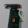
| 1089 forum posts 345 photos | Thanks for replies, and apologies for not getting back to this sooner - my wife has taken on a foster dog so I've been in woodworking mode making stair gates. C'est la vie! William - many thanks for the info about Whitaker rings. I'm not convinced that's what going on here though - brass, very light cuts (~10 thou) slow feed. But maybe - and valuable info even if it isn't. Bob Stevenson - I was initially sceptical about 'stages of resonance', but changing the spindle speed from 550 to 700 rpm gave different 'zones':
and returning to 550 gave results broadly similar to my first photo:
So it's mechanical. I think I understand what's going on now. On the optical effects, I found, unsurprisingly in retrospect, that the 'spectrum' was very much dependent on camera and lighting angles. Thanks Martin. I doubt that I can get much further in understanding optical effects without specialist kit - a trichroic beam splitter would be an absolute minimum requirement I expect. Sadly , I haven't got one I should just be happy that I can get this finish on a mass-market hobby lathe. Robin.
Edited By Robin Graham on 30/07/2021 01:21:13 Edited By Robin Graham on 30/07/2021 01:28:35 |
| Michael Gilligan | 30/07/2021 07:14:38 |
23121 forum posts 1360 photos |
|
| Michael Gilligan | 30/07/2021 08:14:00 |
23121 forum posts 1360 photos | Posted by Michael Gilligan on 25/07/2021 22:38:10:
[…] A diffraction grating will produce the full visible spectrum from white light. MichaelG. . Ref: **LINK** The photo at the bottom of that page ^^^ is an excellent illustration.
. For anyone who might be interested, but didn’t follow that link … here is the referenced photo:
. The ‘double rainbow’ group at lower-right of the picture bears [shall we say] a striking similarity to the pattern that Robin photographed. MichaelG. . Sorry, I can’t be bothered distorting the picture to get the curvature … but it doesn’t take much imagination |
| Michael Gilligan | 30/07/2021 08:17:02 |
23121 forum posts 1360 photos | Posted by Robin Graham on 24/07/2021 22:42:40:
Ref. ^^^ |


Please login to post a reply.
Magazine Locator
Want the latest issue of Model Engineer or Model Engineers' Workshop? Use our magazine locator links to find your nearest stockist!
Sign up to our Newsletter
Sign up to our newsletter and get a free digital issue.
You can unsubscribe at anytime. View our privacy policy at www.mortons.co.uk/privacy
Latest Forum Posts
- *Oct 2023: FORUM MIGRATION TIMELINE*
05/10/2023 07:57:11 - Making ER11 collet chuck
05/10/2023 07:56:24 - What did you do today? 2023
05/10/2023 07:25:01 - Orrery
05/10/2023 06:00:41 - Wera hand-tools
05/10/2023 05:47:07 - New member
05/10/2023 04:40:11 - Problems with external pot on at1 vfd
05/10/2023 00:06:32 - Drain plug
04/10/2023 23:36:17 - digi phase converter for 10 machines.....
04/10/2023 23:13:48 - Winter Storage Of Locomotives
04/10/2023 21:02:11 - More Latest Posts...
- View All Topics
Support Our Partners


Shopping Partners
Subscription Offer

Latest "For Sale" Ads
- Reeves** - Rebuilt Royal Scot by Martin Evans
by John Broughton
£300.00 - BRITANNIA 5" GAUGE James Perrier
by Jon Seabright 1
£2,500.00 - Drill Grinder - for restoration
by Nigel Graham 2
£0.00 - WARCO WM18 MILLING MACHINE
by Alex Chudley
£1,200.00 - MYFORD SUPER 7 LATHE
by Alex Chudley
£2,000.00 - More "For Sale" Ads...
Latest "Wanted" Ads
- D1-3 backplate
by Michael Horley
Price Not Specified - fixed steady for a Colchester bantam mark1 800
by George Jervis
Price Not Specified - lbsc pansy
by JACK SIDEBOTHAM
Price Not Specified - Pratt Burnerd multifit chuck key.
by Tim Riome
Price Not Specified - BANDSAW BLADE WELDER
by HUGH
Price Not Specified - More "Wanted" Ads...
Get In Touch!
Do you want to contact the Model Engineer and Model Engineers' Workshop team?
You can contact us by phone, mail or email about the magazines including becoming a contributor, submitting reader's letters or making queries about articles. You can also get in touch about this website, advertising or other general issues.
Click THIS LINK for full contact details.
For subscription issues please see THIS LINK.
Digital Back Issues


Donate

 Register
 Log-in
Model Engineer Magazine
- Percival Marshall
- M.E. History
- LittleLEC
- M.E. Clock

ME Workshop
- An Adcock
- & Shipley
- Horizontal
- Mill

Subscribe Now
- Great savings
- Delivered to your door

Pre-order your copy!
- Delivered to your doorstep!
- Free UK delivery!
All Forum Topics > Beginners questions > More Q's about surface finish.