Forum sponsored by:

Tyre Guage DRO - capacitance issues?
| Peter Cook 6 | 02/04/2021 19:28:30 |
| 462 forum posts 113 photos | I use a cheap tyre depth guage as a simple quill DRO on my SX1LP. Apparently it is a capacitance based measuring device.
It works very well - as long as I keep my fingers away from it. If I switch it on or zero it using my fingers I get 0.03-0.05mm "jitter" on the display. Zero it with a non conducting object ( plastic T slot cleaner usually) and all is well. Take the device off the mill and it behaves perfectly as does another similar unit I use for measuring the depth of holes. I suspect the issue is a capacitance effect between me and the ground plane provided by the big lump of iron to which it is screwed. Can anyone explain in a bit more detail how these things work, and make any suggestions as to how I might screen the problem. A bit of brass or plastic between the device and the mill head makes no difference. |
| Michael Gilligan | 02/04/2021 20:08:28 |
 23121 forum posts 1360 photos | I can do no better than direct you to the post by Hans U. Meyer. on this thread: **LINK** http://www.pcbheaven.com/exppages/Digital_Caliper_Protocol/ If you need the technical details ... his patents are available on espacenet ... but his closing paragraph is pretty blunt. [ the inventor does not consider capacitative scales suitable for use on machine tools ] MichaelG.
|
| Ian P | 02/04/2021 20:08:42 |
 2747 forum posts 123 photos | There are millions of devices in use that use the same capacitive encoders for linear measurement. I have never heard of one being sensitive to any external (capacitive) influence. Very noisy electrical fields might disturb them but none of the ones I have are even bothered by my high power demagnetiser, they just display the same readings whether its on or off. Does you depth gauge work OK if its off the machine? Ian P
|
| Michael Gilligan | 02/04/2021 20:12:43 |
23121 forum posts 1360 photos | Posted by Peter Cook 6 on 02/04/2021 19:28:30:
[…] Take the device off the mill and it behaves perfectly as does another similar unit I use for measuring the depth of holes. […] .
MichaelG. |
| old mart | 02/04/2021 20:52:24 |
| 4655 forum posts 304 photos |
Edited By old mart on 02/04/2021 20:53:22 |
| Jeff Dayman | 02/04/2021 21:16:09 |
| 2356 forum posts 47 photos | You might try simply adding some plastic or aluminum spacers between the large metal mass of the machine and he scale, and use longer mounting screws. Distance to metal masses can affect readings in capacitive sensors. Nylon or acetal spacers would probably affect readings less than PVC spacers, just FYI, PVC has affected capacitance in several linear measurement instruments I have worked on in the day job. Its' presence changed the dielectric constant in the sensor and caused the readings to be larger than they actually were. Nylon or acetal has less effect. Edited By Jeff Dayman on 02/04/2021 21:19:49 |
| Robert Atkinson 2 | 02/04/2021 21:26:20 |
 1891 forum posts 37 photos | Does it work OK if the mill is turned off at the socket? Fully unplugged at the mains? Robert G8RPI. |
| SillyOldDuffer | 03/04/2021 10:10:59 |
| 10668 forum posts 2415 photos | Posted by Robert Atkinson 2 on 02/04/2021 21:26:20:
... ...
Me too. Interference is highly likely. For it's intended purpose a tyre depth gauge has no need of electrical shielding, so it probably doesn't have any. Expecting one to work whilst attached to an electrically noisy machine tool may be a step too far. Try opening it up and check for missing components. The Lidl digital caliper I dismantled for experimental purposes had no by-pass capacitors fitted, even though PCB has pads ready for them. OK running on Its internal battery but enough hum was picked on the leads from an external power supply to confuse it, and I had to fit a bypass capacitor across the input traces to fix it. Although the electrical supply safety earth will help drain noise away, from an RF perspective they are usually rubbish. Long cable runs connecting to an earth spike may be a low resistance sink at 50Hz, but are likely to be high resistance to the kilohertz noise capable of disrupting an unshielded DRO. The usual compromise is to run the sensitive electronics inside a metal box, and ground the box. Whilst the outer skin of the box is still hot with noise, with care noise doesn't penetrate inside. As Robert might explain further, the design of EMC proof enclosures and electronics is difficult! I'm all for cost-effective home-made solutions, and this one is well-worth trying, but bear in mind re-purposing stuff not made for the job is always a bit risky. Dave
|
| Michael Gilligan | 03/04/2021 11:21:18 |
23121 forum posts 1360 photos | Simple fact: In 2012, the inventor of the capacitative scale concluded his post with ... “I wouldn't want them on a machine tool.” . My inference from that is that the successful implementations are fortuitous, and we should not be surprised by the failures. MichaelG. |
| Andrew Johnston | 03/04/2021 11:40:16 |
 7061 forum posts 719 photos | Some statements by SoD need clarification. A single wire has inductance, so as the frequency of a signal increases the resistance of the wire stays constant, but the impedance increases. One might argue that the effective resistance increases due to skin effect, just to pre-empt the experts. The subject of EMC covers a wide range of areas. The main ones are radiated emissions, immunity to radiation, conducted emissions and ESD. If a device is mains powered then there are also mains borne nasties to be checked. Radiated emissions are fairly simple to control, with the exception of cables. I hate cables inside, or external to, a product. Immunity is also fairly simple, especially for some applications, such as consumer, where the unit doesn't need to continue working, but just has to recover without damage. In other applications, automotive for instance, the unit needs to work throughout immunity tests. It's no good if the ECU hiccups every time a spark plug fires. Conducted emissions are fairly simple to control with appropriate filters and/or shielding. A big cause of EMC test failure is ESD - it has a habit of getting into places it shouldn't, through pathways that one hadn't thought about. Andrew |
| Les Jones 1 | 03/04/2021 13:16:27 |
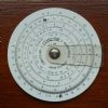
| 2292 forum posts 159 photos | Looking at your picture it looks like the casing is all plastic. I think connecting one side of the battery connections to the mill metal work may solve the problem. Just in case there is already some connection via metalwork that I can't see I suggest making the connection via a capacitor. I suggest about 100 nF but the value is not critical. Also it should not matter which battery connection you connect to. I think there is a removable cover to connections for a remote readout to the right of the battery cover. (As positioned in your picture.) There will be 4 connections. two connect to the battery. (You can check which these are with a DMM on the resistance range.) The other two connections will be data and clock signals. The battery connections under this cover are probably the easiest to make a connection to. Les. |
| Peter Cook 6 | 03/04/2021 13:36:45 |
| 462 forum posts 113 photos | Thanks for all the thoughts, I did some experiments based on the ideas. Robert G8RPI's idea worked. If I touch the head of the mill with one hand while pushing the buttons all works fine. The gauge works perfectly as a simple DRO when the machine is running or stopped. The readings correspond to the markings on the fine feed knob (without the backlash) over the full 25mm range of the quill (and the tyre gauge) as long as I keep fingers away from it. There is no sign of flicker in the readings when the mill is on or off, running or stopped. However - the problem IS electrical interference, but not from the mill. By accident I experimented while the workshop lights were off. All worked perfectly. Switch on the overhead florescent tubes - problem reappears. If I hold the gauge very close to the florescent fittings the readings go haywire. I can only conclude that if I don't touch the mill head while pressing the buttons I am acting as an aerial for the interference from the florescent tubes. So either a better guage to use as a DRO (one with a metal body?), some new light fittings for the workshop or simply touch the mill before zeroing. Thanks again.
PS thanks Les I will try that next. A capacitor will be cheaper than new light fittings. Edited By Peter Cook 6 on 03/04/2021 13:38:53 |
| John Haine | 03/04/2021 14:12:39 |
| 5563 forum posts 322 photos | Check your mill is earthed properly! |
| Steviegtr | 03/04/2021 14:15:12 |
 2668 forum posts 352 photos | Are you sure your lighting is earthed. Steve. |
| John Haine | 03/04/2021 14:53:31 |
| 5563 forum posts 322 photos | It may be light sensitive... |
| John Baron | 03/04/2021 15:05:23 |
 520 forum posts 194 photos | Posted by Peter Cook 6 on 02/04/2021 19:28:30:
I use a cheap tyre depth guage as a simple quill DRO on my SX1LP. Apparently it is a capacitance based measuring device.
It works very well - as long as I keep my fingers away from it. If I switch it on or zero it using my fingers I get 0.03-0.05mm "jitter" on the display. Zero it with a non conducting object ( plastic T slot cleaner usually) and all is well. Take the device off the mill and it behaves perfectly as does another similar unit I use for measuring the depth of holes. I suspect the issue is a capacitance effect between me and the ground plane provided by the big lump of iron to which it is screwed. Can anyone explain in a bit more detail how these things work, and make any suggestions as to how I might screen the problem. A bit of brass or plastic between the device and the mill head makes no difference. Check and make sure that the machine/mill frame is truly earthed ! Any capacitive effect is likely due to any residual voltage on the machine frame. FWITW, my mill didn't even have the earth wire connected to the machine in the control box ! The earth wire was just hung in mid air. Luckily it didn't touch anything that could have caused damage.
|
| Macolm | 03/04/2021 15:19:08 |
 185 forum posts 33 photos | I doubt if earthing the lighting will make much difference. This sort of susceptibility is common with high impedance logic circuits. If the capacitive scale is like most others, the positive of its battery is already connected to the metalwork of the scale. What is happening here is that the “operator” is an aerial receiving radiation from the lighting. The capacitance between his finger and a susceptible point in the scale circuitry is sufficient to induce a big enough "signal" to cause malfunction. If he “earths” himself to the mill metalwork, the unwanted signal is bypassed and its magnitude much reduced.
I doubt if it would matter whether the mill is earthed or not. There is plenty of signal path at the relevant frequencies to the mains wiring via stray capacitances.
Prevention would need an earthed screen, probably impractical in this case.
Edited By Macolm on 03/04/2021 15:20:22 Edited By Macolm on 03/04/2021 15:23:47 |
| Ian P | 03/04/2021 16:46:37 |
2747 forum posts 123 photos | Posted by Michael Gilligan on 03/04/2021 11:21:18:
Simple fact: In 2012, the inventor of the capacitative scale concluded his post with ... “I wouldn't want them on a machine tool.” . My inference from that is that the successful implementations are fortuitous, and we should not be surprised by the failures. MichaelG.
That a little cruel Successful products are more likely the result of hard work by clever engineers The inventor's comments were specifically relating to early examples of the genre, also apart from the ESD aspect (should not affect well designed products) (he mentions ground loops and I took it that was referring to DIY modifications involving external wiring and ground loops. Ian P
|
| Ian P | 03/04/2021 17:09:11 |
2747 forum posts 123 photos | I'm sure Malcolm is right regarding why this particular unit is failing. Digital capacitive based calipers and DRO scale invariably have 'Hardened' Stainless bodies and beams. The important capacitive action takes place on the rear of the display PCB and the PCB pattern on the moving beam (which is backed by the metal of the beam). The important bits then are only a few thou apart and quite well screened in the assembled sandwich and usually impervious to any external influence. In the case of the tyre tread gauge, the beam is usually made from plastic so the moving PCB track and the rear of the main PCB have no connected screening. Not in current use now but I have butchered about six digital calipers to use as simple DRO's. non have ever so much as blinked. I do have a (plastic) tyre tread gauge but its travel is too short to be usefull. Ian p |
| Michael Gilligan | 03/04/2021 17:15:38 |
23121 forum posts 1360 photos | Ian wrote: The inventor's comments were specifically relating to early examples of the genre . Sorry, Ian ... I disagree He made it reasonably clear that the mass-market [capacitative] Chinese scales were based upon his design for Sylvac:
and that
. I remain convinced that it's the capacitative principle that he was dismissing, not external wiring. ... but it doesn't matter; the job's done, and presumably Peter is a happy man. MichaelG. . Edit: __ added reference, for clarity Edited By Michael Gilligan on 03/04/2021 17:18:41 |


Please login to post a reply.
Magazine Locator
Want the latest issue of Model Engineer or Model Engineers' Workshop? Use our magazine locator links to find your nearest stockist!
Sign up to our Newsletter
Sign up to our newsletter and get a free digital issue.
You can unsubscribe at anytime. View our privacy policy at www.mortons.co.uk/privacy
Latest Forum Posts
- *Oct 2023: FORUM MIGRATION TIMELINE*
05/10/2023 07:57:11 - Making ER11 collet chuck
05/10/2023 07:56:24 - What did you do today? 2023
05/10/2023 07:25:01 - Orrery
05/10/2023 06:00:41 - Wera hand-tools
05/10/2023 05:47:07 - New member
05/10/2023 04:40:11 - Problems with external pot on at1 vfd
05/10/2023 00:06:32 - Drain plug
04/10/2023 23:36:17 - digi phase converter for 10 machines.....
04/10/2023 23:13:48 - Winter Storage Of Locomotives
04/10/2023 21:02:11 - More Latest Posts...
- View All Topics
Support Our Partners


Shopping Partners
Subscription Offer

Latest "For Sale" Ads
- Reeves** - Rebuilt Royal Scot by Martin Evans
by John Broughton
£300.00 - BRITANNIA 5" GAUGE James Perrier
by Jon Seabright 1
£2,500.00 - Drill Grinder - for restoration
by Nigel Graham 2
£0.00 - WARCO WM18 MILLING MACHINE
by Alex Chudley
£1,200.00 - MYFORD SUPER 7 LATHE
by Alex Chudley
£2,000.00 - More "For Sale" Ads...
Latest "Wanted" Ads
- D1-3 backplate
by Michael Horley
Price Not Specified - fixed steady for a Colchester bantam mark1 800
by George Jervis
Price Not Specified - lbsc pansy
by JACK SIDEBOTHAM
Price Not Specified - Pratt Burnerd multifit chuck key.
by Tim Riome
Price Not Specified - BANDSAW BLADE WELDER
by HUGH
Price Not Specified - More "Wanted" Ads...
Get In Touch!
Do you want to contact the Model Engineer and Model Engineers' Workshop team?
You can contact us by phone, mail or email about the magazines including becoming a contributor, submitting reader's letters or making queries about articles. You can also get in touch about this website, advertising or other general issues.
Click THIS LINK for full contact details.
For subscription issues please see THIS LINK.
Digital Back Issues


Donate

 Register
 Log-in
Model Engineer Magazine
- Percival Marshall
- M.E. History
- LittleLEC
- M.E. Clock

ME Workshop
- An Adcock
- & Shipley
- Horizontal
- Mill

Subscribe Now
- Great savings
- Delivered to your door

Pre-order your copy!
- Delivered to your doorstep!
- Free UK delivery!
All Forum Topics > Beginners questions > Tyre Guage DRO - capacitance issues?