Forum sponsored by:

Engine thermodynamics
Assumptions for a simplified indicator diagram
| noggin the nog | 03/03/2021 10:37:13 | ||||||||||||||||||||||||
| 3 forum posts | I've been programming my own Walschaerts mechanism simulator and want to add a simplified indicator diagram, but I lack practice in thermodynamics. I will outline my approach to the expansion phase below and hope for comments to confirm that I am on the right track, or to set me right. Steam properties are based on algorithms from **LINK** a - My expansion phase starts with a given volume of saturated steam at a known pressure (typically 6 bar for models), no superheating, yet. | ||||||||||||||||||||||||
| Turbine Guy | 03/03/2021 19:07:52 | ||||||||||||||||||||||||
| 541 forum posts 578 photos | I think that people are reluctant to comment on your assumptions because the expansion of steam in actual steam engines is very complicated. This Indicator LinK compares the actual indicator diagram from tests with theoretical values for saturated and superheated steam. You may find this study helpful for making assumptions. | ||||||||||||||||||||||||
| Nigel Graham 2 | 03/03/2021 21:10:28 | ||||||||||||||||||||||||
| 3293 forum posts 112 photos | Point e - It does, hyberbolically in theory between cut-off and exhaust opening, but wet steam is not a theoretically perfect gas. Engineering in the first half of the last Century produced many books on heat-engine principles obtained from a blend of experiments with actual machines and pure physics. If you've not already done this, it may be worth searching one out, as they covered steam reciprocating as well as turbine and i.c. engines . I don't know if anyone has made indicators for miniature steam engines; either mechanical like the Dobby-McInnes instrument or based on a piezo-electric transducer connected to a charge amplifier and associated electronics. The latter system originated in the 1930s or 40s for testing i.c. engines. Could be an interesting project though! | ||||||||||||||||||||||||
| duncan webster | 03/03/2021 21:38:42 | ||||||||||||||||||||||||
| 5307 forum posts 83 photos | Noggin, As you are ignoring condensation, re-evaporation and wire drawing, I would just have taken an expansion index of 1 (ie PV = const), which is how the engine builders of old worked out the likely power output of their engines. I've done this in excel many moons ago, if you want a copy let me know. The late Bill Hall went one better and worked out the pressure drop in the ports. It gives remarkably good results compared against full size indicator diagrams from Rugby test house. Unfortunately he wrapped it all up with boiler performance calculations, and these subsequently turned out to be less accurate. I independently repeated his port pressure drop sums and got much the same results. Some hairy maths involved, I doubt I could do it now, very rusty. If I can find it can send you a copy if you like. You can download Bill's programs and the theory behind it from 5AT, scroll right down to the bottom of the page. Some clever person might be able to disentangle the engine bit from the boiler bit, I think I have the code stashed away. If you want to include superheat just change the expansion index. Your Walsch model will be at least the 5th. Dockstader, Wallace, Hall, mine and now yours. Nigel, also included in the above link is a paper on taking indicator diagrams from a model size stationary engine. With the onward march of electronics since Bill's time this would be easier now. It's on my to-do list, but that never seems to get any shorter.
| ||||||||||||||||||||||||
| noggin the nog | 03/03/2021 22:28:00 | ||||||||||||||||||||||||
| 3 forum posts | Thank you, Turbine Guy, for the link to Hall's paper on Measuring Steam Engine Performance - his analysis of initial condensation and re-evaporation is interesting and far beyond what I hope to include in a simplified indicator diagram, based only on basic theory. Yes, Nigel Graham, I should probably have made more effort to find the right books, I have mainly used a textbook, "Thermodynamics" by G.J. Van Wylen from 1959, which doesn't cover reciprocating steam engines. My other model steam and locomotive books lack thermodynamic theory. Since I am using algorithms for steam properties, I don't need to assume a hyperbolic curve, and can take account of condensation during the expansion phase. I tried to paste in a sample result, which looks somewhat hyperbolic, starts from cut-off with saturated steam at 0.6 MPa and ends up with 1.3% condensation at release, but failed to paste in this graph with the available tools. I am hoping someone will reply to this post and confirm that I am using a reasonable approach or tell me where I am going wrong. I suppose another possibility is to say that a simplified indicator diagram is a complete waste of effort, because a real, experimental indicator diagram would be so very different. I am hoping that it will be useful by adding a little more information about the effects of the valve events from the simulation.
| ||||||||||||||||||||||||
| J Hancock | 04/03/2021 08:58:21 | ||||||||||||||||||||||||
| 869 forum posts | IF you could find an old GEC-Elliot Valve Catalogue from the 1960's I'm sure you would find just about every conceivable steam/water condition elegantly shown on graphs/nomograms, etc. From the days when we actually made 'stuff ' ourselves. | ||||||||||||||||||||||||
| SillyOldDuffer | 04/03/2021 09:07:43 | ||||||||||||||||||||||||
| 10668 forum posts 2415 photos | Posted by noggin the nog on 03/03/2021 22:28:00: ... I am hoping someone will reply to this post and confirm that I am using a reasonable approach or tell me where I am going wrong. I suppose another possibility is to say that a simplified indicator diagram is a complete waste of effort, because a real, experimental indicator diagram would be so very different. I am hoping that it will be useful by adding a little more information about the effects of the valve events from the simulation.
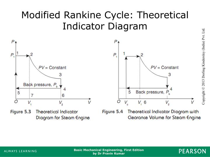
Well, what you're doing is a couple of notches above my pay-grade, but it seems reasonable to me! I did wonder what the practical value of an artificial indicator diagram was because, as you say, a real one would be different. A real indicator diagram reveals faults directly, whilst comparing real diagrams with theoretical perfection suggests where the design needs attention. I'm not sure the effort of artificiallirecreating the curve is worth it when the ideal is already defined: the Rankine Cycle covers steam engines:
If the purpose is to study valve events, perhaps a Reuleaux Diagram would be more useful? Duncan Webster is my hero when it comes to valve gear. We collaborated a while back on porting his valve simulator to Linux. It uses Borland Graphics, and my part concentrated on identifying suitable libraries, fixing a few code compatibility problems, setting up the necessary compiling and linking, and doing some to-and-fro debugging with Duncan. It might be worth a look. The brainy bit is pure Webster. I'm afraid my my mind refuses to translate motion into into mathematical form, so no good asking me about the formula! Dave
| ||||||||||||||||||||||||
| JA | 04/03/2021 09:38:11 | ||||||||||||||||||||||||
 1605 forum posts 83 photos | Noggin I worked with thermodynamics for most of my life but very rarely with steam. Quickly looking at your initial comments you appear to have a good grasp of the subject/problem. At this point, before going on to valve gear which is complex to say the least, I would get a steam chart, or set of steam tables, and a good thermodynamics text book that includes steam. From being an apprentice to retirement the go to book was Rogers & Mayhew, the title was something like "Engineering Thermodynamics". I looked at Amazon last night and they had two second hand copies for about £50 each, ouch. Your county library should have one or the local model engineering club may even do so. Failing that put the word round, a retired engineer could have a copy, have a chat with the local charity shops etc (Charity shops know the value of books. I believe they are sorted at local depots and high value items set aside. All second hand text books from ancient greek grammar to boundary layer theory are worth money), you may be lucky. Do you have a knowledge of calculus? Your comments suggest you may have. If not, also get a A Level maths book, calculus is not difficult. All the best JA Edited By JA on 04/03/2021 09:39:10 | ||||||||||||||||||||||||
| Reg Rossiter | 04/03/2021 10:25:10 | ||||||||||||||||||||||||
 29 forum posts | Posted by Nigel Graham 2 on 03/03/2021 21:10:28:
I don't know if anyone has made indicators for miniature steam engines; either mechanical like the Dobby-McInnes instrument or based on a piezo-electric transducer connected to a charge amplifier and associated electronics. The latter system originated in the 1930s or 40s for testing i.c. engines. Could be an interesting project though! Station Road Steam have produced a digital dynamometer / indicator. Here's the link (if it works) https://www.stationroadsteam.com/ddi/ Reg | ||||||||||||||||||||||||
| duncan webster | 04/03/2021 11:19:03 | ||||||||||||||||||||||||
| 5307 forum posts 83 photos | Realeaux diagrams only work for pure sinusoidal valve motion. A good Walschearts or Stephenson will get near, but not quite there. I've never got on with them, but then I'm biased towards sums Edited By duncan webster on 04/03/2021 11:19:22 | ||||||||||||||||||||||||
| Nigel Graham 2 | 04/03/2021 11:56:45 | ||||||||||||||||||||||||
| 3293 forum posts 112 photos | No, I would not dismiss the theoretical indicator-diagram outright. It will not match reality, but act as a guide to designing the engine and subsequent testing, and I think were used as such industrially. ' Sometimes I wonder how those designers managed without computers and animated graphics of valve-gears! Well, they did, using the Realeaux Diagram or similar to find the virtual-eccentric for the desired full-gear and mid-gear valve travels; and trigonometry and geometrical construction for the motion to give those characteristics. Once the generic formulae and geometry had been established and published, it was probably a lot easier than it seems, and did not need the extra skill of programming a computer to do maths one already knows! The arithmetic by slide-rule and books of tables was slower than by our using a calculator; arguably manual drawing is slower overall than by CAD, but that is all. I am not knocking using computer simulations as such for those with a parallel interest and high skill in computing, but regard them as an interesting adjunct. You still need to understand the machine, and though I do not see using a computer here as automatically an efficient design tool, I respect it as an academic exercise. I do use CAD and occasional spread-sheets, partly because they readily allow determining the effect of changing a value. I have used them in my steam-wagon project, and most recently a spread-sheet for close-approximation metric screw-cutting on my EW lathe. Yet I am designing the wagon's engine from established examples, and need overhaul the lathe before worrying about gear charts. ' Apart from a couple of inherited ones, my handful of old text-books came from a second-hand book-shop with a strong line in transport and other technical themes. They were not expensive, either. I looked for CAD primers too, but the shop had almost no books on computing. The proprietor explained that unlike science and engineering books, IT manuals are out of date so rapidly they are almost un-saleable! ' Reg - Interesting! Costly though; although to be fair that is a multi-purpose system. I was thinking only of indicator tests, not also dynamometer tests, and their system is very much intended for testing locomotives, not road or stationary steam engines. Maybe it's something a large club with its own railway, rather than individual, would buy. My suggestion for a piezo-electric sensor came from one of my old books, plus testing small hydrophones at low frequencies co-incidentally appropriate to steam-engine speeds. Those versed in electronics and computers - and rich enough - could probably make such an indicator, and not withstanding my refusal to worship computers, link it to a storage oscilloscope or a PC-based instrument-simulator like Labview. However; I am not sure how to calibrate the resulting system sufficiently for the project to be worthwhile, but it would entail constructing a calibration-rig rather like a small compressor driven at precisely known speeds. (The trade version is called a 'piston-phone', but for a different purpose so it uses sub-millimetric displacements and deeply sub-Pascal pressures. Not the typical miniature steam-engine's real dV and dP.) ' Basically though, I think all this joule-chasing and computer-programming is interesting academically, but I'd rather make and operate a real reciprocating steam-engine by established principles that give me the chance of it working as well as I can make it, and for its own sake - not try to re-invent the invented! | ||||||||||||||||||||||||
| Howard Lewis | 04/03/2021 12:56:34 | ||||||||||||||||||||||||
| 7227 forum posts 21 photos | A while ago, at a show, someone was exhibiting an indicator, using an Android phone as the read out. Wonder if it still exists? Howard | ||||||||||||||||||||||||
| SillyOldDuffer | 04/03/2021 17:25:56 | ||||||||||||||||||||||||
| 10668 forum posts 2415 photos | The hard part of producing indicator diagrams is finding a suitable sensor. It has to be small enough to fit to a model engine and capable of taking the heat over the required pressure range. Suitable Steam Pressure Transducers appear on ebay occasionally but I can't see any at the moment. Dave | ||||||||||||||||||||||||
| duncan webster | 04/03/2021 17:29:21 | ||||||||||||||||||||||||
| 5307 forum posts 83 photos | you put the pressure sensor on the end of a bit of copper pipe. You get condensation in the pipe and the sensor stays cool. You don't need it very long | ||||||||||||||||||||||||
| Nigel Graham 2 | 04/03/2021 21:14:15 | ||||||||||||||||||||||||
| 3293 forum posts 112 photos | The physical size of the sensor itself is not very important. It does go inside the cylinder but would connected via a tube from a drain-cock mounting. I think though you'd have to consider the effect of the tube itself, and I would think it needs to be as short as practicable consistent with keeping the sensor cool. Using a mechanical indicator In full size the volume of the short pipe from the drain-cock, and the indicator cylinder, is probably insignificant, but would that on a miniature engine be disproportional to the cylinder? If of too small a diameter, though, would it create a smoothing effect so the sensor is not "feeling" a true representation of the pressure in the cylinder? As Duncan points out, the sensor would need protecting from the heat, by water in the tube (like a boiler pressure gauge) and perhaps a heat block. .If the sensor is submersible (a hydrophone), it may be advantageous to have the entire tube and sensor chamber filled with water. | ||||||||||||||||||||||||
| noggin the nog | 04/03/2021 22:01:16 | ||||||||||||||||||||||||
| 3 forum posts | Thank you all for helpful replies and comments to my post. So far, no one has actually said my approach to the expansion phase is unreasonable, I have received some support, and, of course, it is simplified and does not accurately represent real life. So, here are a few results, starting from saturated steam at 0.6 MPa, with 5% clearance volume and release at 95% of the piston stroke:
One advantage of this approach is that it provides direct results for the quality or steam fraction; e.g. 5.6% weight of condensed liquid at release for 40% cut-off. Nor do I need to assume an expansion index of 1 (for PV= constant); in fact, I can find an expansion index of about 1.14 by curve fitting to the results. The hard work behind this is taking the algorithms for steam properties (steam tables) from the Int. Assoc. for the Properties of Water and Steam "Revised Release on the IAPWS Industrial Formulation 1997 for the Thermodynamic Properties of Water and Steam" and putting them into computer code. There are hundreds of numbers that define the functions they have fitted to empirical steam data. Afterwards, it's a doddle; no more table look-ups and interpolation, just subroutine calls. I'd be happy to pass on my Fortran routines for the steam properties if anyone is interested; they only cover the region relevant to live steam, not the full region in the document. I tried the 5at web site for some of Bill Hall's papers, but the links there don't work any more. Advanced-steam.org states that, "in May 2017 the site was effectively lost." My club is the Norwegian Model Engineer Association; we've recently laid down a track at Sørumsand, just NE of Oslo, for 5" and 7¼" gauge. The valve simulation relates to a model of a Norwegian locomotive that I have started building and to another project by club members, who are planning to instrument their locomotive, so I'm passing on the discussion of sensors.
| ||||||||||||||||||||||||
| duncan webster | 04/03/2021 22:22:42 | ||||||||||||||||||||||||
| 5307 forum posts 83 photos | In an engine using saturated steam you don't get adiabatic expansion, there is initial condensation followed later in the stroke by re-evaporation, so steam table values are going to be inaccurate. That's why I suggested that PV=const would be a lot simpler and probably just as accurate (or inaccurate). With a single piston valve or slide valve, as you change the cut off you change the release and compression. If you want copies of Bill Hall send me your email address by pm. It will take a while as the other computer is behind a wall of #2 son's furniture, he's moving house and we are the temporary store. Have a look at this posting by Doubletop Dyno and send him a pm, he has done the engine indicator thing using a PIC and a mobile phone, far too clever for me. I believe he used a fairly cheap pressure sensor on the end of a bit of tube. The tube fills up with condensate, so it doesn't affect the clearance volume. If you can't find him let me know and I'll contact him, I have his email somewhere. The sensor might be one of these sensor Edited By duncan webster on 04/03/2021 22:32:18 |

Please login to post a reply.
Magazine Locator
Want the latest issue of Model Engineer or Model Engineers' Workshop? Use our magazine locator links to find your nearest stockist!
Sign up to our Newsletter
Sign up to our newsletter and get a free digital issue.
You can unsubscribe at anytime. View our privacy policy at www.mortons.co.uk/privacy
Latest Forum Posts
- hemingway ball turner
04/07/2025 14:40:26 - *Oct 2023: FORUM MIGRATION TIMELINE*
05/10/2023 07:57:11 - Making ER11 collet chuck
05/10/2023 07:56:24 - What did you do today? 2023
05/10/2023 07:25:01 - Orrery
05/10/2023 06:00:41 - Wera hand-tools
05/10/2023 05:47:07 - New member
05/10/2023 04:40:11 - Problems with external pot on at1 vfd
05/10/2023 00:06:32 - Drain plug
04/10/2023 23:36:17 - digi phase converter for 10 machines.....
04/10/2023 23:13:48 - More Latest Posts...
- View All Topics
Support Our Partners


Shopping Partners
Subscription Offer

Latest "For Sale" Ads
- Reeves** - Rebuilt Royal Scot by Martin Evans
by John Broughton
£300.00 - BRITANNIA 5" GAUGE James Perrier
by Jon Seabright 1
£2,500.00 - Drill Grinder - for restoration
by Nigel Graham 2
£0.00 - WARCO WM18 MILLING MACHINE
by Alex Chudley
£1,200.00 - MYFORD SUPER 7 LATHE
by Alex Chudley
£2,000.00 - More "For Sale" Ads...
Latest "Wanted" Ads
- D1-3 backplate
by Michael Horley
Price Not Specified - fixed steady for a Colchester bantam mark1 800
by George Jervis
Price Not Specified - lbsc pansy
by JACK SIDEBOTHAM
Price Not Specified - Pratt Burnerd multifit chuck key.
by Tim Riome
Price Not Specified - BANDSAW BLADE WELDER
by HUGH
Price Not Specified - More "Wanted" Ads...
Get In Touch!
Do you want to contact the Model Engineer and Model Engineers' Workshop team?
You can contact us by phone, mail or email about the magazines including becoming a contributor, submitting reader's letters or making queries about articles. You can also get in touch about this website, advertising or other general issues.
Click THIS LINK for full contact details.
For subscription issues please see THIS LINK.
Digital Back Issues


Donate

 Register
 Log-in
Model Engineer Magazine
- Percival Marshall
- M.E. History
- LittleLEC
- M.E. Clock

ME Workshop
- An Adcock
- & Shipley
- Horizontal
- Mill

Subscribe Now
- Great savings
- Delivered to your door

Pre-order your copy!
- Delivered to your doorstep!
- Free UK delivery!
All Forum Topics > Locomotives > Engine thermodynamics