Forum sponsored by:

Dial Graduations
| martin cross 1 | 18/12/2020 22:13:53 |
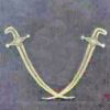
 43 forum posts 59 photos | Having not long ago completed my stepper driven indexing device care of WoW, I was keen to give it a try. My ML10 dials are somewhat faded and dated and non 'zeroable' so with that in mind I decided to have a practice at doing some graduations on a bit of scrap. No point in going further until I know both the device and myself know what we're doing. I decided to do it on the Centec as there's more room and the indexer can be bolted to the bed. The arbor removed and a collet chuck in the MT2 with a carbide boring tool I set about making some marks. First time round round was x10 long ones, second was middling ones and then the shorties. I jumped each existing digit as I came to it. To my surprise it all happened as it should have and with a bit of tidying up looks pretty good for a first attempt. Just got to sort out the numbers now. |
| Nigel Graham 2 | 18/12/2020 22:49:11 |
| 3293 forum posts 112 photos | That looks good! I'm interested here as this is a task I will be faced with ere long, for the hand-wheels on two T&C grinders.. " carbide boring tool... " Were you using the mill basically as a planing-machine, moving the work past a fixed tool, then? That could be the easiest approach for me to use, though I wondered about using a fine-pointed carbide burr.
==== I did engrave a scale on the flat blade of a rather unusual centre-finder / Tee-square, by using a worn centre-drill as makeshift engraving-cutter, in the vertical mill. The lines, in stainless-steel, were a bit coarse though, acceptable for that particular purpose, but not for serious work like your stepper-drive and my T&C grinders. {The centre-finder / square was for cutting cakes accurately, a joke gift last Christmas to a friend who has an engaging habit of methodically dicing slices of cake into small cubes. The centre-finding function, of course, is for marking-out round cakes for accurate slicing - I tested with a pencil and the underside of a saucepan. The scale was calibrated in 1/8 -hands, reflecting her love of horse-riding. } |
| martin cross 1 | 19/12/2020 08:23:02 |
43 forum posts 59 photos | Yes, that's how I approached it. I have a box of carbide boring bits which I bought off fleabay donkeys years ago when you could get stuff real cheap. The boring tool is around 4mm in dia and sits in a DA collet in the mill spindle, setting up is the longest part with the actual 'work' taking maybe 10mins tops. The depth of cut was around 8 thou and length was set by using the table stops for each grouping. Hopefully the picture explains it better, like most people I used YT to see how others do it and went from there. |
| Hopper | 19/12/2020 10:48:51 |
 7881 forum posts 397 photos | Certainly did a very neat job. Your carbide bit must be good and sharp. Certainly a step up from those awful Myford cast Mazak atrocities. What is the "WoW" you refer to in reference to the stepper motor indexer? |
| Emgee | 19/12/2020 10:58:16 |
| 2610 forum posts 312 photos | Posted by Hopper on 19/12/2020 10:48:51:
Certainly did a very neat job. Your carbide bit must be good and sharp. Certainly a step up from those awful Myford cast Mazak atrocities. What is the "WoW" you refer to in reference to the stepper motor indexer?
Most likely this **LINK** Emgee |
| Howard Lewis | 19/12/2020 15:12:34 |
| 7227 forum posts 21 photos | A nice neat job! The last time that I graduated dials, I was less confident, and scribed each line in turn, but essentially used the same technique. The "engraving" tool was a broken centre drill ground to a 60 degree chisel point and held in a drill chuck on the Mill/Drill, so that the cutting edge lay along the table.. A 30 degree point would have produced narrower lines, but at the risk of the tool, being less sturdy. The dial was going to be indexed by a Rotary Table, and division plates. Spacers to fit against a table stop, were made up so that the lines would be of consistent length. Having centred the dial under the spindle,,the "cuttrer" was brought into contact with the dial, before being withdrawn and lowered by 0.010" Having set a table stop to coincide with the far side of the dial, (Some 12 mm ) a "Tens" lines was scribed right across the dial, and then withdrawn, A 8 mm spacer was inserted against the stop to limit the travel, so that the next four lines ("Ones" ) were only 4 mm long, The spacer was then replaced by a 4 mm spacer and the "Five" line scribed. The 8 mm spacer was replaced to mark the next four divisions, before the stops were removed for the next "Ten" line to be marked. The procedure was repeated, until the graduations extended all the way around the dial. A rub with emery or a fine file removed any burrs, and after cleaning up, the dial was ready for fitment. Howard |
| martin cross 1 | 19/12/2020 18:51:52 |
43 forum posts 59 photos | I did get the box of tricks from World of Ward, the stepper, controller and other stuff from fleabay, I also used Andrew Whale's YT build as a good guide with a few changes. All in all once I got the courage to start it wasn't that difficult. Probably the hardest part was getting a box big enough for the power supply and stepper driver to be together. That now resides fitted to the wall of the man cave out of the way. I also found Steve Ward extremely helpful and quick to come back with answers to questions. |
| Nigel Graham 2 | 19/12/2020 22:44:09 |
| 3293 forum posts 112 photos | Martin, Howard - Thank you for the technique descriptions - a good way to avoid the obvious slip! I still have to find a way to fit stops to my milling-machine, as the DRO's fittings have snaffled the original table stops' T-slot. |
| Hopper | 19/12/2020 23:11:37 |
7881 forum posts 397 photos | Thanks Martin. I'll check it out. |
| Howard Lewis | 20/12/2020 11:37:13 |
| 7227 forum posts 21 photos | Nigel, Is it possible that there is enough clearance between the DRO and the table to be able to place the stops in the T slot, inside the fixings for the DRO, so that the moveable stops can still contact the central stop, to limit table movement when required? Then the problem is how do you access the stops to lock them? Change the capscrews for hexagon head screws, that don't foul the back of the DRO scale? Howard |
| Nigel Graham 2 | 20/12/2020 12:13:56 |
| 3293 forum posts 112 photos | Thank you Howard. I am afraid there is no clearance there at all. The machine could do with table-stops fitting again, but I'm blowed if I can see how. The Myford VMC was designed before DRO systems, at least for model-engineers, became available, so does not provide for them. To support the magnetic strip properly, straight, rigid and protected from oil and swarf, it occupies the T-slot; the pick-up uses the fixed stop's mounting-point, and the quadrant-section cover with sealant, hides the lot. The only options would be a bar-stop akin to that on a portable drill, fitted to the table end, or more elaborately but more rigidly a dove-tailed clamp that grips the table slide-ways; with either type acting on the face of the cross-slide. To make it more fun the cross-slide DRO occupies much of the right-hand end space below the table. The left-hand space is not much less cluttered by the system, too. I had no idea before I started just how much metalwork would be necessary in fabricating quite complicated brackets to fit straight things rigidly to awkwardly curved and angled things, and to protect them. I've not investigated but it might be possible to mount a stop-bar on pillars screwed to the end-tray walls, but it may not be possible to find a location for the fixed stop that avoids it all fouling the Y and Z hand-wheels and the DRO.. |
| Howard Lewis | 20/12/2020 20:54:09 |
| 7227 forum posts 21 photos | As ever, one simple job spawns a multitude of others! I used spacers to minimise the risk of problems from backlash and my hamfistedness in reading and setting the handwheel! Howard |
| old mart | 21/12/2020 20:41:45 |
| 4655 forum posts 304 photos | Next time I do some engraving, I will use the same method as yours. Doing all the different lengths in separate stages. My mistake was to cut the lines all in one stage, varying the lengths as I went. As you can see, it is much easier to loose concentration and cut the odd one the wrong length, my 118 scale divisions have two mistakes. |
| Howard Lewis | 22/12/2020 14:11:33 |
| 7227 forum posts 21 photos | O M Cutting all the lines in one stage was what I did. The spacers were used, at the appropriate times to produce lines of the lengths required. (In my case 12mm long for "tens", 8 mm long for "fives" and 4 mm long for "units" ) This meant changing the spacer for each setting after each of the four unit lines to make either a "five" or a "ten". In this way, there was less risk of my failing to index correctly and cut a long line where there should be a short one, or vice versa. It seemed the best way to proof the process against the idiot performing it! Howard
|
| old mart | 22/12/2020 14:55:13 |
| 4655 forum posts 304 photos | I had no problems with the spacing of the lines, 118 was a number that I couldn't achieve with the plates, so the spacing in degrees and minutes was printed out before starting. I recently milled 7 equally spaced dogs on a shaft, and it was easier to just use degrees and minutes than set up a plate and then try to remember how to use it. |
| Rik Shaw | 22/12/2020 17:31:35 |
 1494 forum posts 403 photos | Martin - I am doing something similar at the mo on a tiddly RECORD ML-10 lathe. A nicely made lathe apart from the graduated handwheel dials which are made from black plastic. I am remaking them in ally and the grads are being done in the lathe with a broken 6mm carbide cutter ground with a pointy end. There are forty grads per dial and my luck was in when I found I could index from the first 40T spindle gear on my Warco lathe. When I have done the grads I’ll need to do the numbers - “0” and “0.5” at 180 degrees to the zero. This will be done on my small ISEL CNC machine with the dials mounted on a stub mandrel and held in a 5C collet block. The only problem here was that I do not have a 4th axis for rotary machining. I have overcome this by designing and making a small (6mm dia.) spring loaded drag engraving bit which I have tested on 2.5mm digits and it works a treat. I need four dials to complete the job but I I’ll make five – one as a spare. That will be quite enough graduations for me for some time thank you very much. Rik |
| Bazyle | 22/12/2020 17:41:15 |
 6956 forum posts 229 photos | I'm sure I've seen a tool that helps you get the lines right. Must be on some website somewhere. If only I could find such helpful articles when I want to refer to them. |
| Howard Lewis | 23/12/2020 14:53:02 |
| 7227 forum posts 21 photos | Very likely that someone like G H Thomas or J A Radford made a tool for graduating handwheels. GHT advocated the Universal Pillar Tool for this purpose. Hemingway offer two graduating kits on designs by J A Radford or E Riley.. Howard |


Please login to post a reply.
Magazine Locator
Want the latest issue of Model Engineer or Model Engineers' Workshop? Use our magazine locator links to find your nearest stockist!
Sign up to our Newsletter
Sign up to our newsletter and get a free digital issue.
You can unsubscribe at anytime. View our privacy policy at www.mortons.co.uk/privacy
Latest Forum Posts
- hemingway ball turner
04/07/2025 14:40:26 - *Oct 2023: FORUM MIGRATION TIMELINE*
05/10/2023 07:57:11 - Making ER11 collet chuck
05/10/2023 07:56:24 - What did you do today? 2023
05/10/2023 07:25:01 - Orrery
05/10/2023 06:00:41 - Wera hand-tools
05/10/2023 05:47:07 - New member
05/10/2023 04:40:11 - Problems with external pot on at1 vfd
05/10/2023 00:06:32 - Drain plug
04/10/2023 23:36:17 - digi phase converter for 10 machines.....
04/10/2023 23:13:48 - More Latest Posts...
- View All Topics
Support Our Partners


Shopping Partners
Subscription Offer

Latest "For Sale" Ads
- Reeves** - Rebuilt Royal Scot by Martin Evans
by John Broughton
£300.00 - BRITANNIA 5" GAUGE James Perrier
by Jon Seabright 1
£2,500.00 - Drill Grinder - for restoration
by Nigel Graham 2
£0.00 - WARCO WM18 MILLING MACHINE
by Alex Chudley
£1,200.00 - MYFORD SUPER 7 LATHE
by Alex Chudley
£2,000.00 - More "For Sale" Ads...
Latest "Wanted" Ads
- D1-3 backplate
by Michael Horley
Price Not Specified - fixed steady for a Colchester bantam mark1 800
by George Jervis
Price Not Specified - lbsc pansy
by JACK SIDEBOTHAM
Price Not Specified - Pratt Burnerd multifit chuck key.
by Tim Riome
Price Not Specified - BANDSAW BLADE WELDER
by HUGH
Price Not Specified - More "Wanted" Ads...
Get In Touch!
Do you want to contact the Model Engineer and Model Engineers' Workshop team?
You can contact us by phone, mail or email about the magazines including becoming a contributor, submitting reader's letters or making queries about articles. You can also get in touch about this website, advertising or other general issues.
Click THIS LINK for full contact details.
For subscription issues please see THIS LINK.
Digital Back Issues


Donate

 Register
 Log-in
Model Engineer Magazine
- Percival Marshall
- M.E. History
- LittleLEC
- M.E. Clock

ME Workshop
- An Adcock
- & Shipley
- Horizontal
- Mill

Subscribe Now
- Great savings
- Delivered to your door

Pre-order your copy!
- Delivered to your doorstep!
- Free UK delivery!
All Forum Topics > Workshop Techniques > Dial Graduations