Forum sponsored by:

Myford M Type tailstock alignment
How to go about it please?
| Chris V | 10/10/2020 10:00:12 |
 313 forum posts 42 photos | Good morning all, I have finally mounted up my Myford M type and have found the tailstock is a tad out of alignment. |
| Ady1 | 10/10/2020 13:56:14 |
 6137 forum posts 893 photos | I just line up a couple of dead centre points for general work Unless you have a brand new machine then the bed will be worn and the error varies with distance Use a DTI for more accurate work Only do mega-accuracy when you have to, especially on an old hobby machine GL edit: The AK47 rattles like a box of screws when you shake it because of the tolerances... but it's apparently been quite a successful and reliable product, high accuracy isn't always required |
| Bazyle | 10/10/2020 15:29:24 |
 6956 forum posts 229 photos | The only thing a Morse test bar is necessary for is checking that the morse socket is aligned with the spindle bearings. Nothing else and you can do that with a DTI anyway. If you put a round bar in the 3 jaw and gently turn a little off the eaxtremity it will be by definition aligned with the spindle over that bit. You can then compare that to the periphery of your tailstock barrel with a DTI top an side. Helps to make the turned portion the same dia as the barrel but not essential. Bear in mind next time you sneeze it will go out of alignment so don't sweat over it. |
| Chris V | 10/10/2020 15:56:13 |
313 forum posts 42 photos | Thanks Ady1, thats a fair point well made. Thanks Bazyle, ok I will leave off buying a test bar for now. Yes I don't think dropping the tailstock on the bench helps either...oops! Chris. |
| David George 1 | 10/10/2020 16:17:18 |
 2110 forum posts 565 photos | Hi Chris I use a dial indicator mounted on a piece of bar in the chuck. I put it on to a center or inside the Morse taper.
When you rotate the spindle it will show the amount you are in error and it is easy to adjust sideways . You should always put in a piece steel in the chuck and turn it parrallel to check headstock for misalignment without a center. David Edited By David George 1 on 10/10/2020 16:22:36 |
| Chris V | 10/10/2020 16:42:39 |
313 forum posts 42 photos | Hi David, Ah thank you, I like it! I got a second hand dial indicator, when I depress the tip the needle appears a bit sticky, is this normal or should I be looking for a better one would you say? Chris. |
| David George 1 | 10/10/2020 16:59:54 |
2110 forum posts 565 photos | Hi Chris if the needle sticks it won't tell you if it is true or not. What make is it perhaps a bit of a clean will help. I had one which stuck sometimes and a soak in a cleaning solvent and a good vigorous work at the same time worked wonders after it dried out. If not perhaps a new one? David |
| Chris V | 10/10/2020 17:24:59 |
313 forum posts 42 photos | Thanks David, Yes that's what I thought but thought i'd best check! I will post photos later or in the morning, I think I have two types with different tips... Chris. |
| Howard Lewis | 11/10/2020 09:03:20 |
| 7227 forum posts 21 photos | If you can find an alignment bar that is accurately centred at both ends, Tailstock alignment can be checked by mounting the bar between centres and adjusting the Tailstock until the DTI reading is the same at both ends. Yoiu can make your own alignment bar by taking the largest diameter of bar, prefereably silver stee, or prcision ground bar. The bar is passed therough the hedastock mto leave very small length sticking out of the 4 jaw chuck. The chuck is adjusted to centre the bar to the level of accuracy which you consider acceptable. This procedure is then repeated for the other end of the bar. You then have your alignment bar. Mount between centres and align the tailstock, . If the bar is slender, as it will be for a 1 or 2 MT Headstok bore, use only minimal end load on the centres to avoid introducing any bend. Howard
|
| Chris V | 11/10/2020 10:22:26 |
313 forum posts 42 photos |
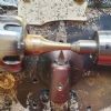
Good morning David & Howard, So attached are my two second hand indicators, the larger one is a bit sticky but if the plunger is part depressed then actually it seems ok. The Verdict one has a different tip? Howard, thank you something like this was in the back of my mind. Its the small bore size creating the issue in my head at least, you would think there is a market for between centres test bars especially for those with smaller lathes but I cannot locate one online?? I was wondering if to make one if I got a larger dia ground bar say 1" or so, one end in the 3 or 4 jaw chuck and then centred the far end say 12" long accurately within a fixed steady, drill the centre and then reverse the bar and centre drill the other end. Does this seem a reasonable way to do it? Chris.
|
| Nicholas Farr | 11/10/2020 10:33:08 |
 3988 forum posts 1799 photos | Hi Chris, this test bar has centres at both ends and the parallel part should be long enough to test for centre alignment 1 MT Test bar Regards Nick. |
| Chris V | 11/10/2020 11:47:03 |
313 forum posts 42 photos | Hi Nick, Thank you yes I have found plenty of these but I'm after a longer one around 12". Have found one in Ali this morning but I shall not be buying that, must be a steel one somewhere?! Regards Chris. |
| David George 1 | 11/10/2020 12:35:08 |
2110 forum posts 565 photos | Hi Chris the verdict DTI woulc be perfect to set the center. How good is the chuck on your lathe if it is reasonable ie within a few thousands of on inch you can put piece of 20 mm steel in the chuck and just turn it parallel with a sharp tool and measure it end to end and see what you get. David Edited By David George 1 on 11/10/2020 12:35:34 |
| Chris V | 11/10/2020 14:12:49 |
313 forum posts 42 photos | Thanks David, good to know about the Verdict one, I shall take a closer look at getting that set up. I don't know as yet about the chuck, once I got the lathe running the one thing I noticed was the tailstock being out so was concentrating on that. With the method you just describe how much metal protruding from the chuck would you suggest given no tailstock is being employed? I was just re acquainting myself with L H Sparey's The Amateurs Lathe and see the method I suggested using a fixed steady above is described in the text, so I must have remembered that! Also a method without using a test dial but a sharp tool in the toolpost and a sheet of white paper to aid seeing whats what,...this could be more my level right now! (-: For checking the dia of a turned piece, is a micrometer (which I have not got) the correct tool or a digital Vernier caliper? Chris. |
| Chris V | 11/10/2020 14:24:59 |
313 forum posts 42 photos | Hi again David, I just realised you didn't actually say don't use the tailstock, I just assumed! Thanks Chris. |
| David George 1 | 11/10/2020 15:14:08 |
2110 forum posts 565 photos | Hi Chris I just noticed you havn't got a micromiter. I have a spare 0 to 1 inch if you want it I have dropped you a message with my email addresses. I couldn't work without one to get things accurate you will struggle with a caliper. David |
| Bazyle | 11/10/2020 15:34:17 |
6956 forum posts 229 photos | The plunger type of dti can suffer from gooey oil on the sliding portion. As mentioned try a little solvent. If you feel inclined to oil it don't use slideway oil, preferably use minimal clock oil which is designed to not dry out. |
| roy entwistle | 11/10/2020 15:43:34 |
| 1716 forum posts | All you need is two centres and a magnifying glass. Years ago we turned a centre in the chuck, put a hard centre in the tailstock and trapped a steel rule between the points |
| Chris V | 11/10/2020 16:19:21 |
313 forum posts 42 photos | Thanks Bazyle, yes good point, I have some light sewing machine oil I can use. Thanks Roy, the rule trick is how I found out it was out of line! Compound magnifying glass is already on order (-: plus another for spare for when I cannot find the compound one! Chris. |
| Howard Lewis | 11/10/2020 17:26:08 |
| 7227 forum posts 21 photos | Whereabouts are you Chris? In UK I hope. One of us could get a piece of sturdy, say 1" dia Sillver steel (which will be 13" long ) and make one for you if you like. My lathe will pass 1" through the Headstock. The larger diameter will be stiffer and less likely to bend with any pressure from the centres, or to sag under its own weight.. If its not too far, you could come and see the whole process, if you wanted It shouldn't take too long Or maybe someone closer to you would do it. But you need not to be claustrophobic, or fastidious! Howard.. Edited By Howard Lewis on 11/10/2020 17:26:43 |


Please login to post a reply.
Magazine Locator
Want the latest issue of Model Engineer or Model Engineers' Workshop? Use our magazine locator links to find your nearest stockist!
Sign up to our Newsletter
Sign up to our newsletter and get a free digital issue.
You can unsubscribe at anytime. View our privacy policy at www.mortons.co.uk/privacy
Latest Forum Posts
- hemingway ball turner
04/07/2025 14:40:26 - *Oct 2023: FORUM MIGRATION TIMELINE*
05/10/2023 07:57:11 - Making ER11 collet chuck
05/10/2023 07:56:24 - What did you do today? 2023
05/10/2023 07:25:01 - Orrery
05/10/2023 06:00:41 - Wera hand-tools
05/10/2023 05:47:07 - New member
05/10/2023 04:40:11 - Problems with external pot on at1 vfd
05/10/2023 00:06:32 - Drain plug
04/10/2023 23:36:17 - digi phase converter for 10 machines.....
04/10/2023 23:13:48 - More Latest Posts...
- View All Topics
Support Our Partners


Shopping Partners
Subscription Offer

Latest "For Sale" Ads
- Reeves** - Rebuilt Royal Scot by Martin Evans
by John Broughton
£300.00 - BRITANNIA 5" GAUGE James Perrier
by Jon Seabright 1
£2,500.00 - Drill Grinder - for restoration
by Nigel Graham 2
£0.00 - WARCO WM18 MILLING MACHINE
by Alex Chudley
£1,200.00 - MYFORD SUPER 7 LATHE
by Alex Chudley
£2,000.00 - More "For Sale" Ads...
Latest "Wanted" Ads
- D1-3 backplate
by Michael Horley
Price Not Specified - fixed steady for a Colchester bantam mark1 800
by George Jervis
Price Not Specified - lbsc pansy
by JACK SIDEBOTHAM
Price Not Specified - Pratt Burnerd multifit chuck key.
by Tim Riome
Price Not Specified - BANDSAW BLADE WELDER
by HUGH
Price Not Specified - More "Wanted" Ads...
Get In Touch!
Do you want to contact the Model Engineer and Model Engineers' Workshop team?
You can contact us by phone, mail or email about the magazines including becoming a contributor, submitting reader's letters or making queries about articles. You can also get in touch about this website, advertising or other general issues.
Click THIS LINK for full contact details.
For subscription issues please see THIS LINK.
Digital Back Issues


Donate

 Register
 Log-in
Model Engineer Magazine
- Percival Marshall
- M.E. History
- LittleLEC
- M.E. Clock

ME Workshop
- An Adcock
- & Shipley
- Horizontal
- Mill

Subscribe Now
- Great savings
- Delivered to your door

Pre-order your copy!
- Delivered to your doorstep!
- Free UK delivery!
All Forum Topics > General Questions > Myford M Type tailstock alignment