Forum sponsored by:

[Project 5] Low Profile Table Clamps
| Lee Jones 6 | 24/05/2020 19:32:50 |
| 258 forum posts 125 photos | Another detour. This time from [Project 4] Sine plate. I need (would like!) some low profile table clamps to be able to resurface stock too large to be held in a vice. Taking inspiration from Harold Hall and Quinn Dunki, I plan to make something like this:
|
| Clive Farrar | 24/05/2020 19:43:40 |
 125 forum posts 41 photos | Good idea. I have made a set of both the high and low profile clamps. The design works and they give good results.
Crack on and get them made.
regards Clive |
| Lee Jones 6 | 24/05/2020 19:47:30 |
| 258 forum posts 125 photos | As some might already know, my facemill is currently out of service, awaiting new inserts. So I thought I'd break out the virgin flycutter. This is my first ever attempt - be kind! So I ground what I thought would be a good shape into some 8mm HSS square bar:
There is side and bottom clearance and a chip break breaker with a small rake angle. The finish was, well, not great:
You can feel every line with your fingernail. Not subtle either. I tried messing around with speeds (180RPM, 280RPM) & feeds and DOC (0.1mm, 0.3mm, 0.50mm, 0.75mm). Not great. Looked okay whilst cutting though: VIDEO: 180RPM - 0.30mm DOC (you have to click to play more than the preview) Cutting deeper shook the house: VIDEO: 180RPM - 0.75mm DOC (you have to click to play more than the preview) |
| Martin Connelly | 24/05/2020 20:12:57 |
 2549 forum posts 235 photos | It may need some radius on the cutting edge. A sharp tool will leave a furrowed surface. 180 rpm with HSS would suit about 45mm diameter. If you have a lower speed it may be worth trying. Alternatively do you have a lathe tool with inserts that you can put in the fly cutter? The other thing to be aware of when sharpening fly cutter bits is that the trailing corner may be rubbing on the uncut surface behind the cutting edge (I know because I have done this). There needs to be material removed behind the cutting edge to avoid this. The front face of the cutter is on the centre of rotation, the back face will be, in this case, 8mm back so can overlap the edge of the circle cut by the front face. There may be witness marks on the cutter if this is happening. Martin C Just thinking about feed rate. The feed rate for a single point cutter such as a fly cutter needs to be a quarter of the feed rate of a four point cutter. For a feed per rev of 0.125mm at 180rpm you need a feed of 180 x 0.125 = 22.5mm/minute which may seem very slow. Edited By Martin Connelly on 24/05/2020 20:20:24 |
| JasonB | 24/05/2020 20:24:03 |
 25215 forum posts 3105 photos 1 articles | Drop your feed, at least 1/4 of what you were using with the face mill as there is only one cut per rev. Simple grind here
Gives this result on ali, finer feed would get it smoother as would rounding the edge if needed.
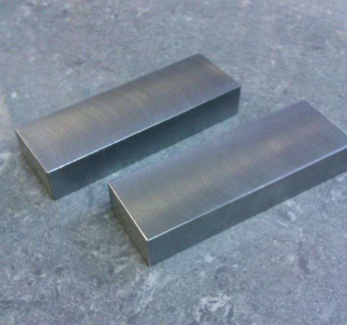
Or on steel, this is 1" x 0.5"
Edited By JasonB on 24/05/2020 20:31:20 Edited By JasonB on 24/05/2020 20:34:12 |
| John Baron | 24/05/2020 20:49:28 |
 520 forum posts 194 photos | Hi Guys, I'm sure that I posted pictures of my fly cutter on here recently, but anyway...
The cutter is a but of 1/4" square HSS. Its symmetrical so both ends are ground similarly. The shaft is 20 mm diameter and the body is a 20 mm thick stainless off cut from a 75 mm bar. It cuts just over 2.5" diameter.
|
| Emgee | 24/05/2020 21:22:57 |
| 2610 forum posts 312 photos | Lee In the video where everything is getting a good shake the cutting force is into the vice loose jaw, I always find it better to set up so if possible the cutting force is taken by the vice fixed jaw. Emgee
|
| not done it yet | 24/05/2020 21:37:07 |
| 7517 forum posts 20 photos | Whichever way you cut, the shaking can be reduced by shifting the job over such that the cutter is not striking the material at almost a right angle. Think conventional milling with an end mill cf climb milling. |
| Lee Jones 6 | 24/05/2020 22:15:49 |
| 258 forum posts 125 photos | Makes sense to me. I have a radius and clearance angles on all sides. I'll try dropping the the RPM and offsetting the work. Thanks. ... when I have the gearbox loaded back into the mill. (long story - don't want to talk about it!) |
| John Baron | 25/05/2020 08:38:42 |
520 forum posts 194 photos | Posted by Lee Jones 6 on 24/05/2020 22:15:49:
Makes sense to me. I have a radius and clearance angles on all sides. I'll try dropping the the RPM and offsetting the work. Thanks. ... when I have the gearbox loaded back into the mill. (long story - don't want to talk about it!) Hi Lee, Now let me guess, you stripped the plastic gear in the mill gearbox ! You are not alone ! I replaced mine with steel gears. It transformed the behaviour and the abilities of the mill. I also discovered that the plastic gear in mine was machined slightly off centre and produced a slight rhythmic thump when the spindle was in low gear.
|
| Lee Jones 6 | 25/05/2020 08:43:29 |
| 258 forum posts 125 photos | Posted by John Baron on 25/05/2020 08:38:42:
Now let me guess, you stripped the plastic gear in the mill gearbox ! That is not correct John. There aren't any plastic gears in my mill, fortunately. If there were, I would have stripped them long ago. I'll put a separate thread up about yesterdays epic.
|
| John Baron | 25/05/2020 09:03:48 |
520 forum posts 194 photos | Hi Lee, That's good, I don't like plastic gears in mills or lathes at all. I didn't see that thread, I'll go and have a look.
|
| Andrew Johnston | 25/05/2020 09:12:02 |
 7061 forum posts 719 photos | It seems a bit odd to have a low profile clamp with a bolt head sticking out. I prefer these gold coloured hexagon style clamps:
I bought the hexagons and offset head screws but made my own T-nuts. Height is less than 7mm. Andrew |
| John Haine | 25/05/2020 09:42:14 |
| 5563 forum posts 322 photos | Andrew shows Mite E Bite clamps. I got a set with the Novamill I bought and use them all the time on that. They are sized for 8mm tee slots, too small I think for the big mill that has 12 mm slots even if I made bigger tee nuts for them. |
| Ron Laden | 25/05/2020 11:04:39 |
 2320 forum posts 452 photos | I can't get my head around the recommended speeds for fly cutting they have never worked for me so I must have been doing something wrong. What does work for me is higher rpm, for Lee, s cuts of 0.3mm and 0.75mm I would go with something in the region 600 rpm for the 0.3 in steel at say 50mm diameter and 350 rpm for the 0.75mm. That is with a HSS cutter usual angles and a rounded nose. I know you will tell me it's wrong but all I can go by is it works, gives a good finish, the mill sounds happy with no issues.
|
| Lee Jones 6 | 25/05/2020 11:27:53 |
| 258 forum posts 125 photos | Posted by John Baron on 25/05/2020 09:03:48:
I didn't see that thread, I'll go and have a look. |
| Lee Jones 6 | 25/05/2020 11:30:22 |
| 258 forum posts 125 photos | Posted by Andrew Johnston on 25/05/2020 09:12:02:
I bought the hexagons and offset head screws but made my own T-nuts. Height is less than 7mm. Why didn't you make all of the parts? |
| Andrew Johnston | 25/05/2020 12:15:04 |
7061 forum posts 719 photos | Posted by Lee Jones 6 on 25/05/2020 11:30:22:
Why didn't you make all of the parts? I'm interested in making parts. Cutting tools, jigs and fixtures get made as I need them, by the quickest means possible. My judgement was that it was quickest to buy the hexagons and screws and make T-nuts to fit the mill. They're not conventional T-nuts. They have a tapped hole for the offset head screw that moves the hexagon. But they also have another tapped hole for a socket head grub screw that locks the T-nut in place. In use the reaction from tightening the hexagon creates a torque on the T-nut that forces the grub screw more tightly into the T-slot. The design of the hexagon has some subtleties. It's not a perfect hexagon, the corners are rounded to prevent them digging into the work. They also have a small lip at the bottom to stop them sliding over the screw head. Both the hexagons and screws are hardened. Of course none of those features would stop me making them but at £50 for 10 it simply didn't make sense. The T-slots on the mill shown are 5/8" (16mm), same as my other mills. Andrew |
| JasonB | 25/05/2020 19:01:15 |
25215 forum posts 3105 photos 1 articles | Posted by Ron Laden on 25/05/2020 11:04:39:
I can't get my head around the recommended speeds for fly cutting they have never worked for me so I must have been doing something wrong. What does work for me is higher rpm, for Lee, s cuts of 0.3mm and 0.75mm I would go with something in the region 600 rpm for the 0.3 in steel at say 50mm diameter and 350 rpm for the 0.75mm. That is with a HSS cutter usual angles and a rounded nose. I know you will tell me it's wrong but all I can go by is it works, gives a good finish, the mill sounds happy with no issues.
Looks like we will both be getting a slapped wrist, I'd be running faster too. Here we are with a 63mm flycutter so probably swinging 80mm dia at the tip (HSS), first cut at 600rpm 40mm/min approx feed and second cut a 300rpm with a feed reduced accordingly, not a bad finish for a slow one handed feed, could have got it better if I was not holding the camera. material 40mm wide EN3b. No sign of vibration. Edited By JasonB on 25/05/2020 19:07:33 |
| John Baron | 25/05/2020 19:18:49 |
520 forum posts 194 photos | Posted by Lee Jones 6 on 25/05/2020 11:27:53:
Posted by John Baron on 25/05/2020 09:03:48:
I didn't see that thread, I'll go and have a look. Thanks Lee. |


Please login to post a reply.
Magazine Locator
Want the latest issue of Model Engineer or Model Engineers' Workshop? Use our magazine locator links to find your nearest stockist!
Sign up to our Newsletter
Sign up to our newsletter and get a free digital issue.
You can unsubscribe at anytime. View our privacy policy at www.mortons.co.uk/privacy
Latest Forum Posts
- *Oct 2023: FORUM MIGRATION TIMELINE*
05/10/2023 07:57:11 - Making ER11 collet chuck
05/10/2023 07:56:24 - What did you do today? 2023
05/10/2023 07:25:01 - Orrery
05/10/2023 06:00:41 - Wera hand-tools
05/10/2023 05:47:07 - New member
05/10/2023 04:40:11 - Problems with external pot on at1 vfd
05/10/2023 00:06:32 - Drain plug
04/10/2023 23:36:17 - digi phase converter for 10 machines.....
04/10/2023 23:13:48 - Winter Storage Of Locomotives
04/10/2023 21:02:11 - More Latest Posts...
- View All Topics
Support Our Partners


Shopping Partners
Subscription Offer

Latest "For Sale" Ads
- Reeves** - Rebuilt Royal Scot by Martin Evans
by John Broughton
£300.00 - BRITANNIA 5" GAUGE James Perrier
by Jon Seabright 1
£2,500.00 - Drill Grinder - for restoration
by Nigel Graham 2
£0.00 - WARCO WM18 MILLING MACHINE
by Alex Chudley
£1,200.00 - MYFORD SUPER 7 LATHE
by Alex Chudley
£2,000.00 - More "For Sale" Ads...
Latest "Wanted" Ads
- D1-3 backplate
by Michael Horley
Price Not Specified - fixed steady for a Colchester bantam mark1 800
by George Jervis
Price Not Specified - lbsc pansy
by JACK SIDEBOTHAM
Price Not Specified - Pratt Burnerd multifit chuck key.
by Tim Riome
Price Not Specified - BANDSAW BLADE WELDER
by HUGH
Price Not Specified - More "Wanted" Ads...
Get In Touch!
Do you want to contact the Model Engineer and Model Engineers' Workshop team?
You can contact us by phone, mail or email about the magazines including becoming a contributor, submitting reader's letters or making queries about articles. You can also get in touch about this website, advertising or other general issues.
Click THIS LINK for full contact details.
For subscription issues please see THIS LINK.
Digital Back Issues


Donate

 Register
 Log-in
Model Engineer Magazine
- Percival Marshall
- M.E. History
- LittleLEC
- M.E. Clock

ME Workshop
- An Adcock
- & Shipley
- Horizontal
- Mill

Subscribe Now
- Great savings
- Delivered to your door

Pre-order your copy!
- Delivered to your doorstep!
- Free UK delivery!
All Forum Topics > Work In Progress and completed items > [Project 5] Low Profile Table Clamps