Forum sponsored by:

Chester Model B
Replacement Motor Wiring
| Patriot | 15/02/2020 14:43:00 |
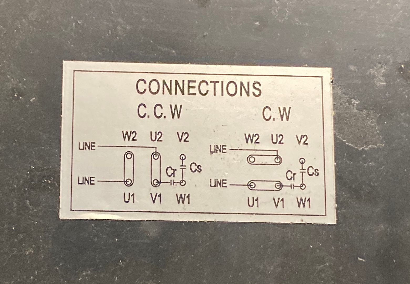
| 2 forum posts | Hello All, Please could you help me connect a new Clarke motor to the Chester Model B Lathe, I’m not the best with electrickery. I’ve searched and searched the internet for various information but can’t seem to find the answer. So before I attach it and power it up I though best to ask the question just to be on the safe side. I assume in order for the motor to rotate both ways I need to remove the 2 brass links and the four wires coming from the power and rotation switches will simulate this. The wires I have are 2 reds but identified V1 / V2 and 2 blacks U1 / U2. Here is a picture of the Clarke Motor cover, could anyone please advise on how to wire it. Thanks a lot. |
| David George 1 | 16/02/2020 13:14:15 |
 2110 forum posts 565 photos | Hi welcome to the forum. Can you give us a little information about the old motor I have looked on the Chester web site but can't see any information about the electrics on there. A picture of the conection would be useful and where are you based gives people a rough idea who local may help. David |
| Les Jones 1 | 16/02/2020 14:55:19 |
| 2292 forum posts 159 photos | I assume that the black wires (U1 & U2) feed the main winding and the red wires feed the auxiliary winding (Via the capacitors on the motor. If this is so then remove both links. Connect wire U1 to terminal U1. Connect wire U2 to terminal U2. Connect wire V1 to terminal V1. Connect wire V2 to W2. Before doing this confirm that the 4 wires are connected as I assume. WITH NO POWER TO THE LATHE confirm that with the forward reverse switch in one position (Forward or reverse. Ignore the off position if it has one.) you get an almost zero resistance reading between wires U1 and V1 and between wires V2 an U2. In the other position you get almost zero resistance V1 and U2 and between V2 and U1. If you do not have a meter I can suggest a method using 4 mains voltage lamps. Les. |
| Patriot | 16/02/2020 16:25:54 |
| 2 forum posts | Hello David & Les. I’m not sure how it was wired originally, a college of mine removed it, pretty sure he has a picture though. Hi Les, I’ll follow your guidance and let you know the outcome. I have a meter, a very basic one so hopefully it’s ok. Thank you so much! |
| Will Taylor 1 | 13/02/2021 16:36:09 |
| 4 forum posts | Hi I have the same problem, I have connected the wires as above, does it matter what capacitor is Cr or Cs as when i turn the lathe on the motor trys to start but just won't go around. This is the same for either direction. Its a brand new motor from chester. Thanks Will |
| Dave Halford | 13/02/2021 16:50:06 |
| 2536 forum posts 24 photos | Posted by Will Taylor 1 on 13/02/2021 16:36:09:
Hi I have the same problem, I have connected the wires as above, does it matter what capacitor is Cr or Cs as when i turn the lathe on the motor trys to start but just won't go around. This is the same for either direction. Its a brand new motor from chester. Thanks Will Cs = start CR = run They are different sizes so yes it does matter. |
| Oldiron | 13/02/2021 17:40:25 |
| 1193 forum posts 59 photos | Patriot use this LINK to see how to post pictures here regards |
| Les Jones 1 | 13/02/2021 18:03:10 |
| 2292 forum posts 159 photos | Does the motor run with no mechanical load on it ? (I.E the drive belt removed.) The larger value capacitor is the start capacitor. I think as it is a new motor you should Return it and get a replacement. Is it connected directly to the mains or via the internal lathe wiring ? I am surprised that Chester have supplied a Clarke motor. Is the connection information supplied with the motor identical to the first post of this thread ? If you want to do some investigation of the fault this is what I suggest. Remove the two link bars. Measure the resistance between U1 and U2. This will be the main winding and I would expect a resistance of less than 10 ohms. Measure the resistance between W1 and W2. This will be the auxiliary winding and it's resistance will be greater than the main winding. (But probably less than 20 ohms.) Measure the resistance between V1 an V2. This is the contacts on the centrifugal switch which should be closed when the motor is stopped and the reading should be very close to zero ohms. Report the readings and we can tell what is probably wrong with the motor. (Not that it really matters as you will have to return it as faulty.) Les. Edited By Les Jones 1 on 13/02/2021 18:05:25 |

Please login to post a reply.
Magazine Locator
Want the latest issue of Model Engineer or Model Engineers' Workshop? Use our magazine locator links to find your nearest stockist!
Sign up to our Newsletter
Sign up to our newsletter and get a free digital issue.
You can unsubscribe at anytime. View our privacy policy at www.mortons.co.uk/privacy
Latest Forum Posts
- *Oct 2023: FORUM MIGRATION TIMELINE*
05/10/2023 07:57:11 - Making ER11 collet chuck
05/10/2023 07:56:24 - What did you do today? 2023
05/10/2023 07:25:01 - Orrery
05/10/2023 06:00:41 - Wera hand-tools
05/10/2023 05:47:07 - New member
05/10/2023 04:40:11 - Problems with external pot on at1 vfd
05/10/2023 00:06:32 - Drain plug
04/10/2023 23:36:17 - digi phase converter for 10 machines.....
04/10/2023 23:13:48 - Winter Storage Of Locomotives
04/10/2023 21:02:11 - More Latest Posts...
- View All Topics
Support Our Partners


Shopping Partners
Subscription Offer

Latest "For Sale" Ads
- Reeves** - Rebuilt Royal Scot by Martin Evans
by John Broughton
£300.00 - BRITANNIA 5" GAUGE James Perrier
by Jon Seabright 1
£2,500.00 - Drill Grinder - for restoration
by Nigel Graham 2
£0.00 - WARCO WM18 MILLING MACHINE
by Alex Chudley
£1,200.00 - MYFORD SUPER 7 LATHE
by Alex Chudley
£2,000.00 - More "For Sale" Ads...
Latest "Wanted" Ads
- D1-3 backplate
by Michael Horley
Price Not Specified - fixed steady for a Colchester bantam mark1 800
by George Jervis
Price Not Specified - lbsc pansy
by JACK SIDEBOTHAM
Price Not Specified - Pratt Burnerd multifit chuck key.
by Tim Riome
Price Not Specified - BANDSAW BLADE WELDER
by HUGH
Price Not Specified - More "Wanted" Ads...
Get In Touch!
Do you want to contact the Model Engineer and Model Engineers' Workshop team?
You can contact us by phone, mail or email about the magazines including becoming a contributor, submitting reader's letters or making queries about articles. You can also get in touch about this website, advertising or other general issues.
Click THIS LINK for full contact details.
For subscription issues please see THIS LINK.
Digital Back Issues


Donate

 Register
 Log-in
Model Engineer Magazine
- Percival Marshall
- M.E. History
- LittleLEC
- M.E. Clock

ME Workshop
- An Adcock
- & Shipley
- Horizontal
- Mill

Subscribe Now
- Great savings
- Delivered to your door

Pre-order your copy!
- Delivered to your doorstep!
- Free UK delivery!
All Forum Topics > General Questions > Chester Model B