Forum sponsored by:

Colchester Student Mk1 Won't Start
| Richard Kirkman 1 | 25/11/2019 13:37:59 |
| 334 forum posts 799 photos | Afternoon, First post on here so here we go In the summer I purchased a Mark 1 Colchester student completely unseen and untested (forgive me) the man said it was working fine although i'm unsure how long its sat around for. I spent a while cleaning it up and getting ready to start it as it looks like it hadn't been used for many years. I had to fit a new fuse box to the garage and a 32 amp socket so the rotary converter would work. I'm using a Clarke pc40 3.5hp rotary phase converter to power the lathe. The lathe is 3hp I had to stop as i moved back to university for a few months, but I have had a day or two now to play with it while i'm home So, i have done some work on the lathe, replacing a sliding sleeve in the headstock so now i believe it is mechanically functional. I didn't want to switch it on without replacing this part as I thought it could have done more damage. So, going plugging everything in, its all looking fine, I switch the motor on and nothing happens, just nothing. When I switch the lathe to on with coolant pump, the coolant pump makes noise as if it is working (but i have yet to clean out the tank and fill it, so i don't know if its pumping or just making noise) I have taken off the front cover to look for issues but i am definitely no electrician, i have no idea what i'm looking at. I have the wiring diagram, but i have no idea what to look at and then how to test for issues. The rotary phase converter has a current reading on it so you can see how much it is pulling, even with the coolant pump on, it remains at zero. Does anyone have an idea of where to start? I understand which wires are which and where they're going to, but not the things they're going into. there is a loose piece pictured in the casing that looks broken and i have no idea where it may have gone. The reverse forward switch which has been added looks fine to me and all the pieces inside the case are fine. I still have yet to clean around the back of the lathe, but it will clean up to the same as the rest of the lathe, just very thick grime I have taken plenty of pictures, but i will be unable to access the lathe again till the 13th December as I have to go back to University. Not too sure how the photos work on this, so i'l attach a link to the album. If people can't view that then i'll post them normally https://photos.app.goo.gl/eWFpzzp7p7Wasart9
Thanks |
| SillyOldDuffer | 25/11/2019 16:24:40 |
| 10668 forum posts 2415 photos | Not familiar with the Colchester Student so let's hope an expert turns up soon! I see the lathe is 415V 3-phase so take care poking around inside. That the pump is running shows power is getting from the Clarke Converter to the lathe. Best to start with the obvious first: 1. Are all the fuses good? 2. does the lathe have any electrical safety interlocks, and are they set correctly? Like an emergency stop button that needs to be reset, or a chuck guard that must be closed before the motor will operate, or that Limit Switch. If all the interlocks are set, and fuses good, turning power on should operate the contactor with an audible click. The contactor is a relay containing three switches, one for each phase to the motor, probably with a fourth used in connection with the safety interlocks to prevent the motor re-starting after a power cut . If the contactor isn't working, check the circuit that powers its coil. If the coil has power, then you need a new contactor. The broken part may be the centre tongue from whatever this is: (I think it's the contactor) Slightly worrying that someone has already been at the electrics. and the missing indicator lamp: Tempting to assume it's a major rewiring job, but it's possible it was left in running condition. Check everything obvious first. Then look for missing connections, bust contactor, broken rotary switch, or duff motor. That will involve tracing the circuit with a test meter, which is another subject. Any Colchester owners able to positively identify the contactor? Are those fabric insulated pillars inside short wide coils thermal cut-outs that might need TLC? Dave
|
| Phil Whitley | 25/11/2019 19:24:38 |
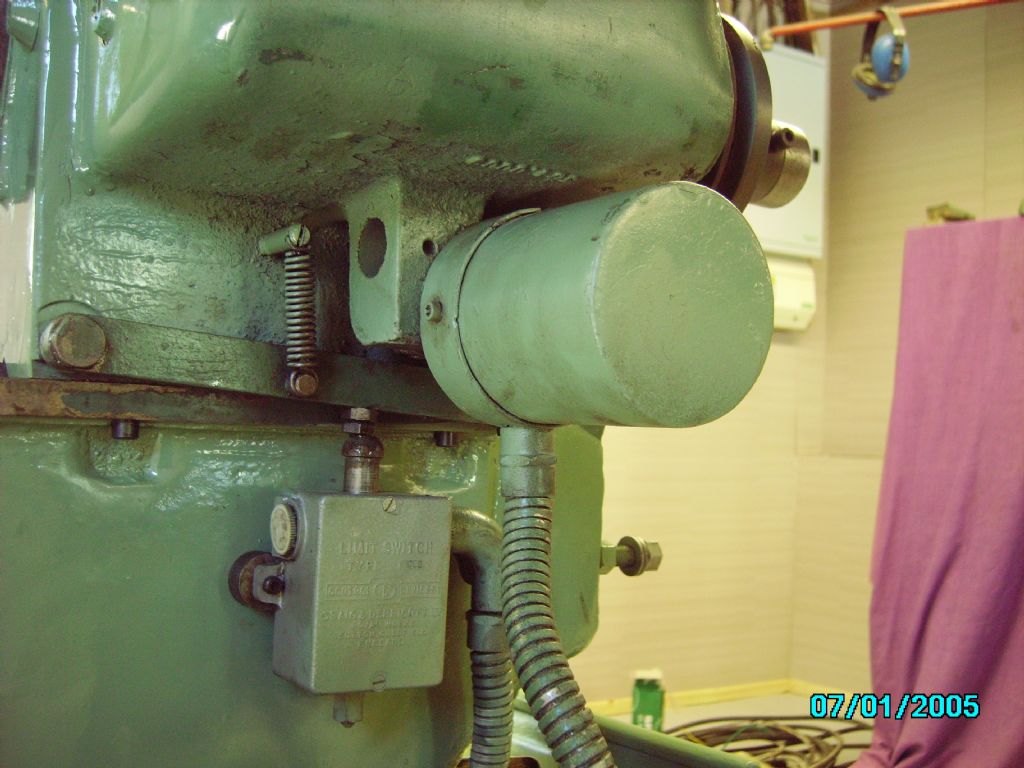
 1533 forum posts 147 photos | Hi there Richard, first off, do you have a manual? If you search the files at colchester lathe user, you can download one, if you have problems I can send you a pdf. There is a wiring diagram in it. In the pic below, the square box on the back of the headstock operates the contactor, and is operated by pressing the front lever with the red knob down.
Just a small thing, and probably wont apply, but the Student has a key switchin the opposite end of the metal cabinet, you put a small key in it and turn it, and it opens the cupboard doors, and turns the power on. most of these are disconnected very quickly by owners, but worth checking. You need a mains tester with which you can check the presence of mains power at the contactor terminals safely!! First, check that the front lever is operating the switch correctly. can you send some pics I have a student Mk1 and I am next to it every day, and can answer most questions you might have by checking mine. Where are you in the UK?
Phil Driffield East Yorkshire |
| Phil Whitley | 25/11/2019 19:38:41 |
1533 forum posts 147 photos | Colochester lathe user has changed to https://colchesterlathe.groups.io/g/main, The manual is in the files section for download. just thought if the coolant pump is running switch is either bridged out, or in the on position, forget that bit! Edited By Phil Whitley on 25/11/2019 19:42:41 |
| Clive Foster | 25/11/2019 19:43:54 |
| 3630 forum posts 128 photos | Long time since I had anything to do with rotary converters but I'm not sure that a 3.5 hp (nominal) converter is going to be enough to reliably start a 3HP motor. Especially an economy one like the Clarke. One common issue with a marginal system is insufficient voltage to operate the control gear. The control gear should always be connected across the mains input leg nor one side from mains and one side to the generated (wild) leg. Theoretically it should matter with a rotary converter, although vital wit a static converter. In practice that and similar issues have caused me serious frustration in the past. Clive Edited By Clive Foster on 25/11/2019 19:44:17 |
| Andrew Johnston | 25/11/2019 19:50:25 |
 7061 forum posts 719 photos | Hmmm, doesn't look like a rotary converter to me. A proper rotary converter uses a single phase motor to drive a 3-phase motor working as a generator. It provides a true 3-phase supply and can run multiple motors up to the total horsepower rating. The box illustrated by SoD looks more like a static converter that uses a capacitor in conjunction with the driven motor to create an artificial third phase. The give away are the switches on the front labelled in hp; used to switch in different values of capacitor for different loads. Note that a 3-phase motor will run on two phases, but is rather "lumpy". So that might be what the coolant pump is doing. A static converter may, or may well not, run the contactors and other electrical items between the supply and motors depending upon how it is wired and the voltages required. Many 3-phase contactors run phase to phase (415V) not phase to neutral (240V). In the absence of a 3-phase supply beg, steal or borrow a proper rotary converter. True rotary converters are pretty noisy, so you'l know if you have one! Andrew |
| mal webber | 25/11/2019 19:55:39 |
 154 forum posts 309 photos | HI, I have a mk1 1/2 student run by a pc 60 and sometimes not often it trips like a overload switch behind the front panel on the lathe side, I will take a picture if you like, but like has been said make sure all guards are in place first has they have safety switches . P.S I did use the pc 40 with my student for about 4 yrs it done the job for the first year and then decreased in power after that i.e would not run higher speeds but would still run lower ones, up in till the point the chuck needed a bit of help to start and if it did not start straight away the trip switch would trip out on the lathe. Edited By mal webber on 25/11/2019 20:07:14 |
| Simon Williams 3 | 25/11/2019 20:23:19 |
| 728 forum posts 90 photos | Richard - Have you got a neutral connected to the switch gear - I think I'd expect the contactors to need a neutral to the coil, not be connected line to line. But if they are line to line the point above about being connected to the transformed input phases and not to the false phase is valid. What voltage is your converter actually applying, and is it three phase at all? If you are not familiar with machine electrics that might sound like gobbledegook, so can you tell us where you are, maybe someone with the relevant expertise can assist "hands on". Good luck, you need a competent sparks used to working with industrial machinery. Keep your fingers out of the birds nest, them wires bite! |
| Andrew Johnston | 25/11/2019 20:47:56 |
7061 forum posts 719 photos | Posted by Simon Williams 3 on 25/11/2019 20:23:19:
Have you got a neutral connected to the switch gear - I think I'd expect the contactors to need a neutral to the coil, not be connected line to line. On all my industrial machine tools the contactors run phase to phase because a) I've measured the coil voltages and b) the machine inputs are 4 wires - three phases and earth - so there is no neutral. Andrew |
| Clive Foster | 25/11/2019 21:00:42 |
| 3630 forum posts 128 photos | Just looked up the PC40 manual. Its a static converter so it needs the lathe motor running to produce a reasoanble approximation to three phase. The control gear coils must be connected across the 220 V mains input lines to work. The third leg is generated by the motor itself so no power there until its running. Probably not man enough to run the motor properly under load but it ougth to start it off load. In my view frustration in a box. Static converters can be seriously weird devices, especially when you get much over 1 hp rating and often don't behave how the books claim. Although, as Andrew says, rotary converters can be made as a single phase motor driving a three phase generator the term is generally understood to refer to a basic static converter driving a matched, permanently connected, three phase motor. That motor is frequently termed a pilot motor. It acts as a generator to produce the third (wild) phase leg and somewhat stabilise the voltages, currents and phase shifts of the three legs os that you can simply connect and run a machine without too much fiddling. Most boxes use an ordinary motor but, ideally a specially wound device should be used that isn't quite the same as a motor. Most static converters can be made into an adequate approximation of a rotary converter by adding a pilot motor. Best to use a big old fashioned one rather than a modern high efficiency one. So called "Energy star" motors can be pants at this. I always used to use a motor somewhat bigger than the converter, eg add 5 Hp motor to a 3.5 static converter to make a 3 hp rated rotary. Despite what the commercial producers like Transwave may have you believe getting things working really well is more black art than plug'n play. Seem to be lots of pertinent research papers from the wind power community about making Stienmetz (the fancy name for the circuits and wiring involved, connected devices work better. Pity none of it has made it down to affordable workshop level kit. Clive |
| Richard Kirkman 1 | 25/11/2019 21:12:10 |
| 334 forum posts 799 photos | Right, Thanks for all the responses so far, I have A LOT to look at. If anything I do enjoy this as I like learning about machines, as long as i can get it working. Dave-Thanks for your response- the fuses are probably fine, although i haven't taken anything to pieces in there so i'll check that when i'm back. The lathe has a No Volt Release built in as far as i know? but it has no safety parts like an emergency stop button. The main off/on/on with coolant pump switch provides a very large satisfying clunk but I am unsure if that's the same thing as the contactors you're on about as i haven't been brave enough to turn it on without the cover on, not that that would help as of the 3 pins that need to be plugged in. I don't understand what some of the components in there even do like this entire part in the picture below
But in this part it looks like the contacts are very rusted, if they are contacts that is. As far as the light switch not being there, I would like to fit one, but I cant seem to find a genuine replacement for the part(any direction from anyone appreciated?) Ideally i'd like to understand every part in here just so i know what's going on. Someone has definitely been in here before me as when i first took the cover off I found this drawing
Phil- I see you're in Driffield, I'm at University in Hull, but the lathe resides at home in Darlington. I haven't looked at the key in the end of the lathe, however the cupboard doors do open, so I presume its on. I think your lathe might be the mk1.5 as it looks like it has the reverse forward switch on the back of the lathe, where as mine was added 3rd party ( I think, definitely doesn't look official). Apart from that, the inside of the components in the lathe should be the same when it comes to the electronics. The contactor makes a nice clunk noise when i activate the lever And yes I do have the manual specifically for the earlier model and this is the wiring diagram from it Clive and Andrew- Yes it most likely is a static converter then, not rotary (It's also not making any noise so definitely not rotary). Perhaps a short term solution if I can upgrade. The motor plate says its 2.5hp so would a static 3.5hp converter possibly manage? If not, i may have access to a proper rotary one if i beg
Mal-So your pc40 worked with your mk1.5 for a while. My mk1 has a 2.5hp motor and as far as i'm aware, the mk1.5 had a 3hp motor. So maybe the pc40 will work a bit better for mine (still short term fix)? Simon- Yep thats all gobbledegook, however i'll try my best. As andrew says, yes there are 3 live wires and earth, so no neutral. The converter is definitely 3 phase, but as Andrew also said, its not true three phase. According to the converter, its applying 0 amps, but it says that it has power from 230v mains so 415v should be coming out, I don't think the lathe is drawing anything from it though. Thanks, I'll try not to electrocute myself. Thank you everyone for your comments so far, I still cannot check anything till the 13th December but this'll hopefully help me with some understanding of what's going on before I attempt anything
|
| Stuart Bridger | 26/11/2019 08:31:41 |
| 566 forum posts 31 photos | I suspect you may have several issues here, but I would agree with Clive, you may be on a hding to nothing with the static converter. If the pseudo third phase is not up and running and the control gear is connected to that phase, the contactor coil will never get energised. It might be worth swapping around a couple of the phases on the input to see if you can get the control gear energised. I also don't like the look of some of the old switch gear. The main contactor looks well past its sell by date. Poking around 415v if you don't know what you are doing is a dangerous sport. If you could get someone in with Electrical knowledge it would help. |
| Richard Kirkman 1 | 26/11/2019 17:02:47 |
| 334 forum posts 799 photos | Posted by mal webber on 25/11/2019 19:55:39:
HI, I have a mk1 1/2 student run by a pc 60 and sometimes not often it trips like a overload switch behind the front panel on the lathe side, I will take a picture if you like, but like has been said make sure all guards are in place first has they have safety switches . P.S I did use the pc 40 with my student for about 4 yrs it done the job for the first year and then decreased in power after that i.e would not run higher speeds but would still run lower ones, up in till the point the chuck needed a bit of help to start and if it did not start straight away the trip switch would trip out on the lathe. Edited By mal webber on 25/11/2019 20:07:14 Mal, how did you initially get your student to work? Was it just plug and play for you with your pc40 or did you have any issues? |
| Phil Whitley | 26/11/2019 18:23:24 |
1533 forum posts 147 photos | Hi Richard, mine is definitely a Mk1, but looking at the levers on yours I would say it is a very early mk 1, I do not have the "safety apron". If you can hear the contactor pull in when you press the front lever down, and the switch for the main motor is set to on, then it should run, stupid suggestion, the chuck guard doesnt have a safety switch on it? The main contactor is pulling in, and usually the safety switches are wired into the coil circuit, but who knows if a second contactor has been added. Turn OFF and disconnect the power, and with a multimeter, see if you can test from the contactor to the reversing switch, and from the reversing switch to the motor. This does depend on whether the reversing switch is before the contactor or after it, but I suspect it is after, it is a start anyway! Phil
|
| Phil Whitley | 26/11/2019 18:55:12 |
1533 forum posts 147 photos | Does the motor have a panel covering it?, can you hear it buzzing if you place a long screwdriver on the motor case and listen to the handle? Try starting it with the belts off! You need one of these https://www.ebay.co.uk/p/Martindale-Vt12-Voltage-Continuity-2-Pole-Tester-Indicator-Gs38-Compliant/1523025759 they can be bought cheaper than this. Remember that each phase is a about 240v, but there is 400v between phases, you could use a tester like this to test between phase and earth at the motor to read the individual phase voltages, but I am getting a bit worried about suggesting that you go poking around with a tester inside a live machine, much safer with the power off and using an avo, but they will read continuity which can break down when voltage is applied if you have, for instance bad contactor contacts. Phil |
| Richard Kirkman 1 | 26/11/2019 20:03:27 |
| 334 forum posts 799 photos | Posted by Phil Whitley on 26/11/2019 18:23:24:
Hi Richard, mine is definitely a Mk1, but looking at the levers on yours I would say it is a very early mk 1, I do not have the "safety apron". If you can hear the contactor pull in when you press the front lever down, and the switch for the main motor is set to on, then it should run, stupid suggestion, the chuck guard doesnt have a safety switch on it? The main contactor is pulling in, and usually the safety switches are wired into the coil circuit, but who knows if a second contactor has been added. Turn OFF and disconnect the power, and with a multimeter, see if you can test from the contactor to the reversing switch, and from the reversing switch to the motor. This does depend on whether the reversing switch is before the contactor or after it, but I suspect it is after, it is a start anyway! Phil
I'm getting quite confused with all these terms. Specifically which part is the contactor, is it this part? And if its not this part, what is this part and what does it do and why? Or is it this part at the back. The piece that says limit switch has a pin that moves up and down when i switch the lathe on from the lever on the front and makes a click as it goes into place. But, I'm not too sure what noises i'm looking for? And no, there isn't a switch on the chuck guard. Also, i have access to the motor round the back so I am able to check if it buzzes but i have not done so yet. Thanks Edited By Richard Kirkman 1 on 26/11/2019 20:04:37 |
| Guy Lamb | 26/11/2019 23:02:38 |
| 109 forum posts | Don't know if it's been mentioned but from memory Colchester students have a limit switch on the gearbox door, presumably to knock the power off if its opened whilst in motion. Might be worth checking. Guy |
| mal webber | 26/11/2019 23:55:03 |
154 forum posts 309 photos | Posted by Richard Kirkman 1 on 26/11/2019 17:02:47:
Posted by mal webber on 25/11/2019 19:55:39:
HI, I have a mk1 1/2 student run by a pc 60 and sometimes not often it trips like a overload switch behind the front panel on the lathe side, I will take a picture if you like, but like has been said make sure all guards are in place first has they have safety switches . P.S I did use the pc 40 with my student for about 4 yrs it done the job for the first year and then decreased in power after that i.e would not run higher speeds but would still run lower ones, up in till the point the chuck needed a bit of help to start and if it did not start straight away the trip switch would trip out on the lathe. Edited By mal webber on 25/11/2019 20:07:14 Mal, how did you initially get your student to work? Was it just plug and play for you with your pc40 or did you have any issues? Hi Richard ,yes it was plug in and play with no problems started up great in highest gear but the power started to drop of after about a year but ever so slowly, run the 3hp motor for 4 years plus so in my book that will do for me.lathe not used every day of course but 2 to 3 day on the trot was often, that's about 3hrs a night use . Mal P.S the pc 40 has a trip switch as well Edited By mal webber on 26/11/2019 23:57:36 Edited By mal webber on 26/11/2019 23:58:49 Edited By mal webber on 27/11/2019 00:02:08 |
| mal webber | 27/11/2019 00:17:03 |
154 forum posts 309 photos | Richard forgot to mention that I had trouble running it with the suds pump not sure if pump was faulty but just left it disconnected. Mal.
|
| Robert Atkinson 2 | 27/11/2019 07:33:00 |
 1891 forum posts 37 photos | Posted by Richard Kirkman 1 on 26/11/2019 20:03:27:
Posted by Phil Whitley on 26/11/2019 18:23:24:
Hi Richard, mine is definitely a Mk1, but looking at the levers on yours I would say it is a very early mk 1, I do not have the "safety apron". If you can hear the contactor pull in when you press the front lever down, and the switch for the main motor is set to on, then it should run, stupid suggestion, the chuck guard doesnt have a safety switch on it? The main contactor is pulling in, and usually the safety switches are wired into the coil circuit, but who knows if a second contactor has been added. Turn OFF and disconnect the power, and with a multimeter, see if you can test from the contactor to the reversing switch, and from the reversing switch to the motor. This does depend on whether the reversing switch is before the contactor or after it, but I suspect it is after, it is a start anyway! Phil
I'm getting quite confused with all these terms. Specifically which part is the contactor, is it this part? And if its not this part, what is this part and what does it do and why? Or is it this part at the back. The piece that says limit switch has a pin that moves up and down when i switch the lathe on from the lever on the front and makes a click as it goes into place. But, I'm not too sure what noises i'm looking for? And no, there isn't a switch on the chuck guard. Also, i have access to the motor round the back so I am able to check if it buzzes but i have not done so yet. Thanks Edited By Richard Kirkman 1 on 26/11/2019 20:04:37 Hi Richard, The item pictured with 3 contacts separated by grey (asbestos?) insulation panels is the contactor. The contacts don't look great. If you can hear this clunking with the start lever operation the PC40 is powering it. Do you have a multimeter / test meter? You really need to get into some fault finding. First thing would be to check the contactor contact resistance you can do this with it unpowered by manually closing it , pushing down on the brown (Tufnol) insulator that carries the moving contacts and then checking the resistance across each contact. Robert G8RPI. |


Please login to post a reply.
Magazine Locator
Want the latest issue of Model Engineer or Model Engineers' Workshop? Use our magazine locator links to find your nearest stockist!
Sign up to our Newsletter
Sign up to our newsletter and get a free digital issue.
You can unsubscribe at anytime. View our privacy policy at www.mortons.co.uk/privacy
Latest Forum Posts
- *Oct 2023: FORUM MIGRATION TIMELINE*
05/10/2023 07:57:11 - Making ER11 collet chuck
05/10/2023 07:56:24 - What did you do today? 2023
05/10/2023 07:25:01 - Orrery
05/10/2023 06:00:41 - Wera hand-tools
05/10/2023 05:47:07 - New member
05/10/2023 04:40:11 - Problems with external pot on at1 vfd
05/10/2023 00:06:32 - Drain plug
04/10/2023 23:36:17 - digi phase converter for 10 machines.....
04/10/2023 23:13:48 - Winter Storage Of Locomotives
04/10/2023 21:02:11 - More Latest Posts...
- View All Topics
Support Our Partners


Shopping Partners
Subscription Offer

Latest "For Sale" Ads
- Reeves** - Rebuilt Royal Scot by Martin Evans
by John Broughton
£300.00 - BRITANNIA 5" GAUGE James Perrier
by Jon Seabright 1
£2,500.00 - Drill Grinder - for restoration
by Nigel Graham 2
£0.00 - WARCO WM18 MILLING MACHINE
by Alex Chudley
£1,200.00 - MYFORD SUPER 7 LATHE
by Alex Chudley
£2,000.00 - More "For Sale" Ads...
Latest "Wanted" Ads
- D1-3 backplate
by Michael Horley
Price Not Specified - fixed steady for a Colchester bantam mark1 800
by George Jervis
Price Not Specified - lbsc pansy
by JACK SIDEBOTHAM
Price Not Specified - Pratt Burnerd multifit chuck key.
by Tim Riome
Price Not Specified - BANDSAW BLADE WELDER
by HUGH
Price Not Specified - More "Wanted" Ads...
Get In Touch!
Do you want to contact the Model Engineer and Model Engineers' Workshop team?
You can contact us by phone, mail or email about the magazines including becoming a contributor, submitting reader's letters or making queries about articles. You can also get in touch about this website, advertising or other general issues.
Click THIS LINK for full contact details.
For subscription issues please see THIS LINK.
Digital Back Issues


Donate

 Register
 Log-in
Model Engineer Magazine
- Percival Marshall
- M.E. History
- LittleLEC
- M.E. Clock

ME Workshop
- An Adcock
- & Shipley
- Horizontal
- Mill

Subscribe Now
- Great savings
- Delivered to your door

Pre-order your copy!
- Delivered to your doorstep!
- Free UK delivery!
All Forum Topics > Help and Assistance! (Offered or Wanted) > Colchester Student Mk1 Won't Start