Forum sponsored by:

Evolution of a Boring and Facing Head
| Graham Meek | 27/03/2019 12:01:26 |
| 714 forum posts 414 photos | Back in the late 1980's I adapted the standard Emco boring head design to do facing work as well .
While many of examples of my Boring and Facing head have been made around the world the design did not suit everyone. Some did not like the original large dial used by Emco, not realising this was in fact there to aid balancing.
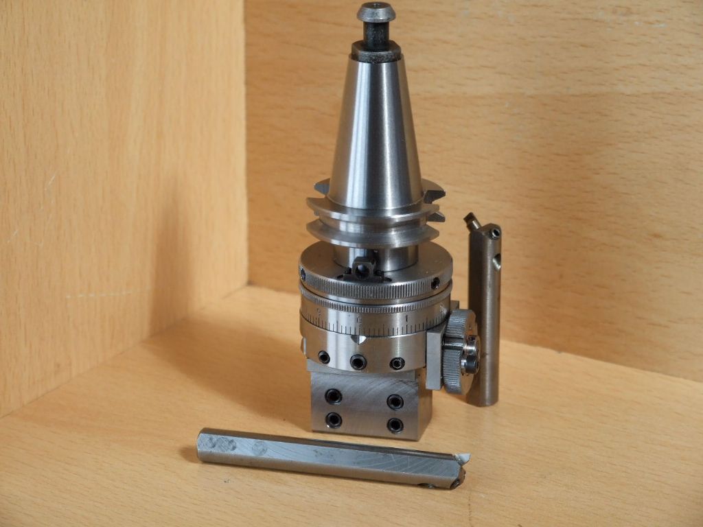
As the original design was an adaptation to meet an the needs of a pending job at the time. I decided to start with a clean sheet of paper and design a boring head which had the dial concentric with the main body. Certain features of the original Emco design have been retained. No point trying to re-invent the wheel. The New version has a continuous drive to the feedscrew during facing operations un-like my initial design which has an intermittent, 2 speed, bi-directional drive. The New head has a single speed but still feeds in two directions. There is an inbuilt adjustable clutch to cut out the feed when the stops are being used. The Dial is Zero setting and one complete revolution removes 0.1 mm from the bore. Each numbered division removes 0.01 mm from the bore. The largish knurled ring on the end is the selector mechanism for the direction of feed. The Mk V head came about after a friend asked me to make him a B&F Head as he could not find one suitable for his new Mill. I must admit I have not seen any to suit this particular mill with a facing capacity. The Mk I being the initial Emco design.
More details of the evolution to follow, Regards Gray, |
| Graham Meek | 27/03/2019 17:53:41 |
| 714 forum posts 414 photos | When I tooled up the X1 milling machine I decided the original boring and facing head, (Mk II), was just too big for this machine. I therefore made the Mk III which has a 50 mm body, compared to the original which had a 66 mm body.
This boring head saw more use on the Emco FB 2 in the end and it proved to be a much more in keeping with the size of the machine and the work that I do. Thus when it came to making a NEW version of the B&F head with constant drive I decided that the 50 mm body would be the basis of the prototype. This then is the Mk IIII, and has seen considerable use on my version of the Clayton Steam wagon and the Fiat 702 Tractor that I am building.
Regards Gray, |
| John Reese | 27/03/2019 18:36:00 |
 1071 forum posts | Beautifully done. |
| Simon Collier | 27/03/2019 20:04:51 |
 525 forum posts 65 photos | What a lovely thing to wake up to, as I sit in bed with coffee and pad. I will struggle to understand the facing drive but I hope it will become clear eventually. Thanks for posting Gray. |
| Graham Meek | 28/03/2019 10:44:52 |
| 714 forum posts 414 photos | Thanks for the kind comments, this B&F head was a joint venture. As so often happens lately this head was mentioned in passing during a conversation with John Slater. Who has done some 3D views of the internal workings of the Mk IIII head. When I said I had schemed out a smaller head he said he would like to see the drawings. Thus another collaboration started on the MK V. John however was not the recipient of the Mk V shown, that was for another machine. John is building his own version for his mill. I wonder how many have thought the Mk V was on an ISO 30 shank?
The actual taper is a BT 20, Regards Gray, |
| Graham Meek | 29/03/2019 14:08:08 |
| 714 forum posts 414 photos | One last photograph to show the lineage,
Regards Gray, |
| John Hinkley | 29/03/2019 14:13:24 |
 1545 forum posts 484 photos | Gray, I like the look of the middle one; it's the sort of size to which I can relate, both in construction and use terms. Have you, or do you intend to publish the plans anywhere? I've already built my version of the one described in your book. John
|
| Graham Meek | 30/03/2019 10:25:58 |
| 714 forum posts 414 photos | The article and 3D images are away at the publishers for the Mk IIII or 50 mm B&F Head. Given the challenges of making the Mk V an article may get written in the near future. Regards Gray, |
| Graham Meek | 11/06/2020 10:59:14 |
| 714 forum posts 414 photos |
Following numerous requests for drawings of a larger version of the 36 mm and 50 mm Concentric Dial B&F Heads. Of a size along the lines of my original 66 mm design that appeared some years ago. I have recently completed this design of a 66 mm Concentric Dial version and thought I would share this with the Forum. I have also included a view of the component parts prior to assembly. The worm drive for this version is a modified 2.5 mm pitch screw thread and the helical worm gears are 30 degree Pressure Angle. Many have asked how the drive is achieved in previous postings on this Forum, and elsewhere, so this should give those wishing to know most of the answers Articles on all three versions are either in hand, or already away at the publishers. Regards Gray,
|
| Mark Slatter | 14/11/2020 20:14:47 |
| 65 forum posts 7 photos | What fantastic boring heads! Have any articles on these been published yet? |
| bernard towers | 14/11/2020 21:48:58 |
| 1221 forum posts 161 photos | i originally made the screw cutting dog clutch from grahams book about five years ago, works faultlessly. with recent lockdown the book came out again and the boring and facing head was made, a beautiful thing. Out of interest grahams drawings are the only ones I have used which so far have had no mistakes this is in itself a pleasure |
| Mark Slatter | 14/11/2020 22:48:32 |
| 65 forum posts 7 photos | Hello Bernard, thanks for the reply. Can I ask for the title of the book you are referring to? I presume the drawings in the book are for the Mk1 version? I'd love to have a go at making one of his later concentric dial heads, what a beautiful and useful tool for the workshop! |
| bernard towers | 15/11/2020 23:44:18 |
| 1221 forum posts 161 photos | Projects for your workshop vol 1 from tee publishing |
| Ian Johnson 1 | 16/11/2020 14:57:50 |
| 381 forum posts 102 photos | The 50mm one would be ideal for my small mill, this is a contender for a next project. Superb work Gray, the ISO20 version is especially nice! IanJ |
| Graham Meek | 16/11/2020 16:36:34 |
| 714 forum posts 414 photos | Posted by Ian Johnson 1 on 16/11/2020 14:57:50:
The 50mm one would be ideal for my small mill, this is a contender for a next project. Superb work Gray, the ISO20 version is especially nice! IanJ Hi Ian, Thanks for the kind words, The 50 mm design has just been published in the Home Shop Machinist. Part 1 was in the Sept/Oct issue and part 2 has just been published in the Nov/Dec issue. The smaller 36 mm size was sent to Neil for publication a while back. I suspect current Covid problems have delayed the publication of this article. The article for the 66 mm version is nearing completion. Hope these notes help, Regards Gray, Hi Bernard, Thanks for your kind comments concerning my work and the drawings. I never offer anything for publication that I have not made myself. The original drawings which go into the workshop usually come back before the computer with red marker pen signifying a modification, or omission. As the years go by these drawings seem to be getting more red on them. Regards Gray,
Edited By Graham Meek on 16/11/2020 16:43:29 |
| Raymond Anderson | 16/11/2020 17:09:13 |
 785 forum posts 152 photos | As usual Gray, superb workmanship. and so well designed. Simply stunning pieces of kit. |
| Graham Meek | 18/11/2020 11:24:29 |
| 714 forum posts 414 photos | Thanks Raymond for the kind words, it has been a while since we last exchanged emails, I hope all is good with you. My best regards Gray, |
| Neil Wyatt | 18/11/2020 12:02:19 |
 19226 forum posts 749 photos 86 articles | Graham is right, Covid has meant I am getting through the 'queue' of submitted articles rather more slowly than usual. I hope we can publish the 36mm design in the spring. Neil
|
| James Walker | 28/11/2022 20:07:47 |
| 11 forum posts 1 photos | Graham - I have a larger mill, nearly Bridgeport sized so the 66mm version is of keen interest. Has it been published yet? If so where? regards - James. |
| John Hinkley | 30/11/2022 09:39:20 |
1545 forum posts 484 photos | Graham, Can I add my name to the list of enquirers for the drawings for the 66mm version? I could try to scale up the plans in issue 311 of MEW, but would prefer to work from original, definitive drawings with their attendant dimensions. In order to fully understand the construction and operation of the tool, I like to model it first in 3D. It helps me to visualise it and work out the most efficient way for me to tackle the machining processes involved. Regards, John
|


Please login to post a reply.
Magazine Locator
Want the latest issue of Model Engineer or Model Engineers' Workshop? Use our magazine locator links to find your nearest stockist!
Sign up to our Newsletter
Sign up to our newsletter and get a free digital issue.
You can unsubscribe at anytime. View our privacy policy at www.mortons.co.uk/privacy
Latest Forum Posts
- *Oct 2023: FORUM MIGRATION TIMELINE*
05/10/2023 07:57:11 - Making ER11 collet chuck
05/10/2023 07:56:24 - What did you do today? 2023
05/10/2023 07:25:01 - Orrery
05/10/2023 06:00:41 - Wera hand-tools
05/10/2023 05:47:07 - New member
05/10/2023 04:40:11 - Problems with external pot on at1 vfd
05/10/2023 00:06:32 - Drain plug
04/10/2023 23:36:17 - digi phase converter for 10 machines.....
04/10/2023 23:13:48 - Winter Storage Of Locomotives
04/10/2023 21:02:11 - More Latest Posts...
- View All Topics
Support Our Partners


Shopping Partners
Subscription Offer

Latest "For Sale" Ads
- Reeves** - Rebuilt Royal Scot by Martin Evans
by John Broughton
£300.00 - BRITANNIA 5" GAUGE James Perrier
by Jon Seabright 1
£2,500.00 - Drill Grinder - for restoration
by Nigel Graham 2
£0.00 - WARCO WM18 MILLING MACHINE
by Alex Chudley
£1,200.00 - MYFORD SUPER 7 LATHE
by Alex Chudley
£2,000.00 - More "For Sale" Ads...
Latest "Wanted" Ads
- D1-3 backplate
by Michael Horley
Price Not Specified - fixed steady for a Colchester bantam mark1 800
by George Jervis
Price Not Specified - lbsc pansy
by JACK SIDEBOTHAM
Price Not Specified - Pratt Burnerd multifit chuck key.
by Tim Riome
Price Not Specified - BANDSAW BLADE WELDER
by HUGH
Price Not Specified - More "Wanted" Ads...
Get In Touch!
Do you want to contact the Model Engineer and Model Engineers' Workshop team?
You can contact us by phone, mail or email about the magazines including becoming a contributor, submitting reader's letters or making queries about articles. You can also get in touch about this website, advertising or other general issues.
Click THIS LINK for full contact details.
For subscription issues please see THIS LINK.
Digital Back Issues


Donate

 Register
 Log-in
Model Engineer Magazine
- Percival Marshall
- M.E. History
- LittleLEC
- M.E. Clock

ME Workshop
- An Adcock
- & Shipley
- Horizontal
- Mill

Subscribe Now
- Great savings
- Delivered to your door

Pre-order your copy!
- Delivered to your doorstep!
- Free UK delivery!
All Forum Topics > Workshop Tools and Tooling > Evolution of a Boring and Facing Head