Forum sponsored by:

The Workshop Progress Thread 2019
| JasonB | 01/01/2019 06:57:22 |
 25215 forum posts 3105 photos 1 articles | Report your modelling and workshop milestones in this thread. Anything else should go into the What did you do thread 2018 posts can be found in this thread
Edited By JasonB on 01/01/2019 07:34:58 |
| Ron Laden | 01/01/2019 08:35:43 |
 2320 forum posts 452 photos | Jason, your engine is coming along nicely, looking really good. Ball bearings and not plain bearings.? just wondered what your thinking was on that. Ron |
| JasonB | 01/01/2019 10:08:30 |
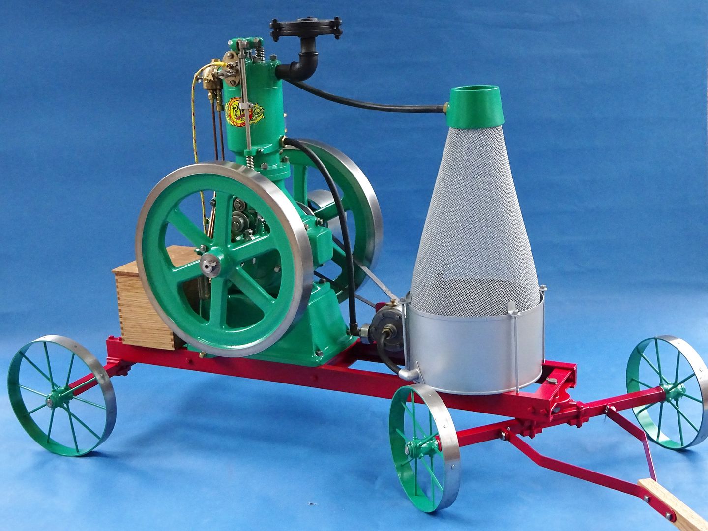
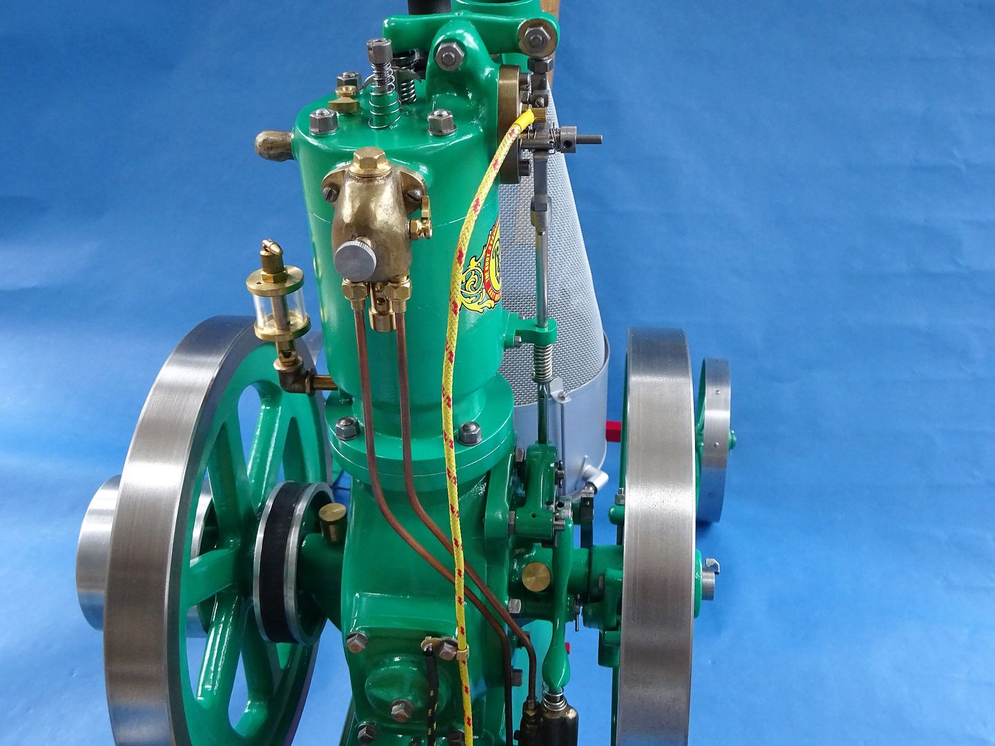
25215 forum posts 3105 photos 1 articles | Ron, the flame lickers don't have a lot of power so the ball races should offer less friction than bronze. have also gone for unshielded for the same reason. |
| Ron Laden | 01/01/2019 10:43:29 |
2320 forum posts 452 photos | Posted by JasonB on 01/01/2019 10:08:30:
Ron, the flame lickers don't have a lot of power so the ball races should offer less friction than bronze. have also gone for unshielded for the same reason. I thought it must have something to do with ease of running, is the Forest engine similar re power or does the gas mix give them more. |
| JasonB | 01/01/2019 12:27:34 |
25215 forum posts 3105 photos 1 articles | The Forest would have more power though the original was only rated at 1/15th horsepower from it's 2.5" bore |
| Joseph Noci 1 | 02/01/2019 06:00:23 |
| 1323 forum posts 1431 photos | In late 2017 I obtained a neat 3 phase 250watt motor with attached Varvel 100:1 gearbox and thought that was ideal for a bench powered hacksaw. It sat under that bench for a year..Mid December last year I challenged myself by starting the project, but on the basis that I do it only with bits from the scrap box/store, etc, ie, no purchase of any bits not within the workshops! ( Except hacksaw blades, of course...) And so.. The base is a piece of 150mm x 75mm x 8mm channel iron, shapered flat and milled for the vice, etc. The saw frame slides are 18mm Hex, steel for the fixed and brass for the reciprocating frame. The slides pivot on large bearings that are also on the main drive shaft out the gearbox. In the top hat is the 500watt VFD, and the on/off/speed control. Speeds are from about 2 strokes/sec to position the frame when checking stroke length (inching..) up to 130 strokes/sec.
Views with all guards in place.
The hydraulics are seen here - The tube (right) from an old mountain bike front shock
This is the cam activated blade lifter during the return stroke - worked OK, but eliminated by appropriate crank moments placement and geometry, with only a damper used. See it working in the video
The drive con-rod, ready to weld up. The crank has three throws giving strokes of 220mm, 160mm and 80mm, allowing optimal use of the full blade for different stock sizes.
The oil distribution grooves in the fixed hex slides - fed from an oil well in the top support - one-shot oiling..
The oil well.
The saw frame and slides.
Blade Tensioner.
The vice/screw - made from an old imperial X leadscrew from and EMCO FB2 mill.
The shaper flattening..
And...
The TIG welding on the Ali covers was so good, I just painted over and did not smooth down! ( patting my back..) All my 'CAD' design drawings for the complicated bits...
Hydraulics..
A video link below- does not neatly stand on its own, but shows the workings well enough. The blade reliever during return stroke was a trial only really - the cam has a 2mm offset, which through the lever gave a blade raise of 4mm. This needs to reduce to maybe 1mm, ie, cam lift of 0.5mm or so - But the adjustment of the hydraulic drop rate is just to finicky in this mode, and the damper only mode, coupled with proper crank throw moments works best Also, the blade front is 1.5mm lower than the rear mount, and that with correct damping drop rate works very well. Took 2 weeks to build, finished on the 1st Jan 2019...And Neil, I was ALSO crimping wires for this on Christmas day! Joe |
| martin perman | 02/01/2019 09:51:52 |
 2095 forum posts 75 photos | Thats some saw. Martin P |
| Joseph Noci 1 | 02/01/2019 15:19:32 |
| 1323 forum posts 1431 photos | Thanks Martin.. After building the saw I decided I had better do something about all my poor condition drill bits.. I have a neat T&C grinder that does drills very well, but is a huge pain to setup, so tends to not be used for drill sharpening. I always thought a jig such as the one in March 2000 (issue 64) MEW was a good idea, and when I got hold of a square block 5C collet holder I decided this morning to knock up a similar adaptor for my grinder. This is the universal tool head on my grinder - does all, but requires a lot of set up.
The 5C collet block
With a sharpened drill still inserted
Method of aligning the drill edges
The universal tool head with extraneous removed and a fabricated Collet block table fitted
Collet block with drill in place. The block is heavy and stays in place with the tilt of the table for the relief angles.
25deg secondary relief set
Grinding secondary relief.
5deg primary relief set
View of motion tables from above.
6.4mm drill swarf - not to unbalanced..
3mm drill swarf. ( poor, soft and string Ali..)
Joe |
| Paul White 3 | 02/01/2019 15:37:37 |
| 109 forum posts 23 photos | Joe, Did you really mean 2 and 130 strokes/sec. I know you build fast but HSS blades must be essential! A very neat product at any speed. |
| Joseph Noci 1 | 02/01/2019 16:00:45 |
| 1323 forum posts 1431 photos | Hello Paul! A good New Year to you Sir! Yes, become bored over the holidays, so got stuck in..And yes, 2 to 130 strokes/s. When the stroke is set to 80mm for example, I could really do with even around 150 strokes/s or faster..At the 220mm stroke, 100 strokes/s is comfortable. I do use HSS blades, but I also cut blade lengths from bandsaw blade stock and drill the tension pin holes with a carbide drill - those blades work even better, as I can easily do down to 12 teeth/inch which is great for thicker Ali stock. Anyway, it was a lot of fun in the making. Nice to hear from you! Joe |
| Paul White 3 | 02/01/2019 16:11:22 |
| 109 forum posts 23 photos | Joe, I should have guessed, did not consider stroke variation, making an even more impressive build.
Looks like a busy year, 2 days into it and 2 projects finished
.Paul |
| JasonB | 02/01/2019 16:21:07 |
25215 forum posts 3105 photos 1 articles | Joe, if you are using a 100:1 gearbox then you would need the motor to be running at 780,000 rpm to get 130 strokes per second are you sure it is not strokes per minute, even then its 13000rpm |
| Joseph Noci 1 | 02/01/2019 17:08:56 |
| 1323 forum posts 1431 photos | As usual, Jason is Wide Awake! I have too many bits on the go here...The 100:1 is for the gearbox on a motor I am using for another cheese curd stirrer for my good wife - and that one is giving me a headache, and so was on the brain, so to say! Sorry, to set things straight - The saw's motor is 1345RPM @ 50Hz ( according to its descriptor plate). The gearbox is a Varvel 15:1 box, and the speed should have been in STROKES/min !! Seems I got most of everything wrong.. I think I'll just back off and try again next year.... Should really edit that post 'cause that is plain crappy posting.. Joe |
| daveb | 02/01/2019 18:57:18 |
| 631 forum posts 14 photos | I wouldn't mind getting it all wrong if my jobs turned out like that. I like the drill jig, just what I need for my Clarkson. Very nice work Joe! Daveb |
| Joseph Noci 1 | 02/01/2019 20:31:41 |
| 1323 forum posts 1431 photos | Daveb, Since the Clarkson has both table traverse and feed, you would not need anything more than what I have implemented - just a firm tray/guide to hold the square collar block and a means of setting azimuth and elevation angles. Since the drill tip included angle can be fixed, that one is easy to do, and then a means of setting 25deg and 5deg ( or whatever takes your fancy) for the primary and secondary facets in the remaining plane is all that is needed. I was very pleased with the accuracy of the collar block - it is a chinese block and was inexpensive, but is ground parallel to within plus/minus 0.002mm across all flats! Fitting a 10mm 5C collet with a 10mm carbide rod in the collet and placing the block flat on a granite block I find less than 0.006mm variation with a height gauge and dial indicator between granite surface and top of the carbide rod, on all 4 block faces. Part of that variation will also be from the collet, so all together not bad at all. The 5C collet also offers more contact length across the drill flutes which seems to give better drill location on smaller drills ( sub 3mm) than I was obtaining with ER20 collets. I appreciate the ease of removing the block from the receptacle and being able to quickly inspect the tip grinding progress, and then replacing the block with no loss of register. What I need to do is make up some sort of optical/magnifying aid to better align the drill cutting edges parallel with two sides of the block, especially the smaller drill. Maybe a small video camera in line with the drill bit tip, and projected onto a PC screen with a cross-hair overlay. Problem with that is that it starts to become too complicated again to get all the bits out, connected and working, before I can sharpen a drill bit...A monocular magnifying eye piece in line would work fine, but I have few skills in that dept - and no optics or lenses to play with! Joe |
| David Standing 1 | 02/01/2019 22:22:37 |
| 1297 forum posts 50 photos | Joe I am now at the point where I recognise a photo that is clearly your work before I even see who has posted it! |
| Jeff Dayman | 02/01/2019 22:36:16 |
| 2356 forum posts 47 photos | Joseph - re the covers TIG welding - you keep going like that and there will be grinder disc factories shutting down! Great work, well done. |
| Joseph Noci 1 | 03/01/2019 06:07:06 |
| 1323 forum posts 1431 photos | Posted by David Standing 1 on 02/01/2019 22:22:37:
Joe I am now at the point where I recognise a photo that is clearly your work before I even see who has posted it! Mmmm, David, methinks I need to change the colour that I paint things.. Joe |
| Ian McVickers | 15/01/2019 21:30:39 |
| 261 forum posts 117 photos | I'm in the middle of making a version of the upgraded universal head for the Clarkson MK1 Tool Grinder as shown on the bedroom workshop site. Base plate has been milled to size and a recess cut to accept the upper part. A centre line was engraved across the plate as well but it doesn't show up too well on the photo. Upper part turned to size at 95mm diameter and 110mm high then cut in the bandsaw, about 30 minutes worth of cutting. Hopefully at the weekend I will get some time in the shop to finish milling it and possibly get a scale engraved around the bottom edge.
|
| JasonB | 17/01/2019 19:36:17 |
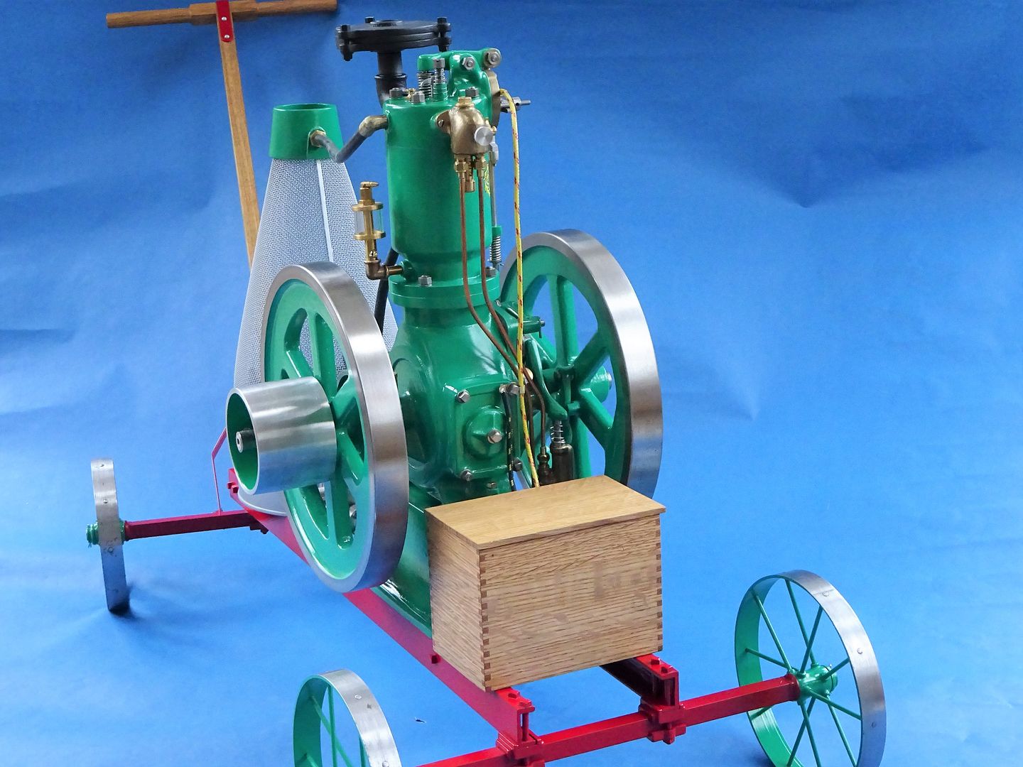
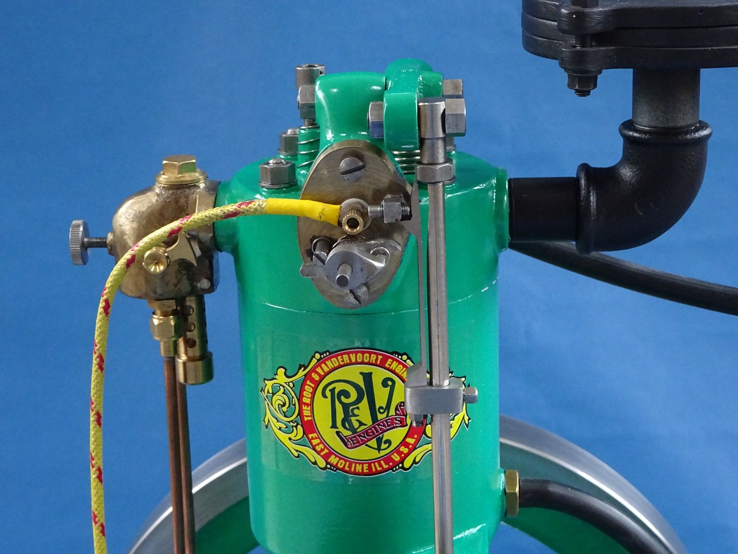
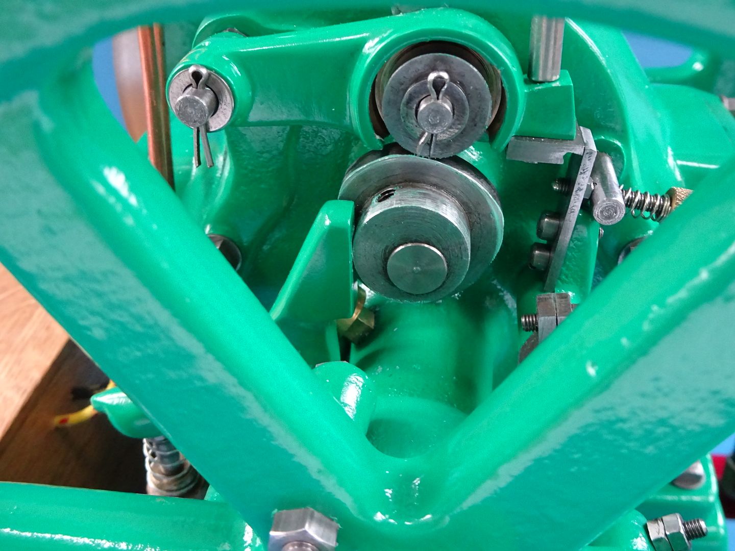
25215 forum posts 3105 photos 1 articles | After letting the paint harden off for far longer than it really needed I thought it was about time to see if I could remember how it all went back together, I think this looks about right and there were no bits left over
[img]
It is not quite as lively now it is back together though that may be due to having to fit a new ring as I broke one during assembly though compression seems reasonable. I have not got the governor latching in this video as it does not need it at these speeds. Hopefully with a bit more tinkering it will liven up and the governor can be set to work. |


This thread is closed.
Magazine Locator
Want the latest issue of Model Engineer or Model Engineers' Workshop? Use our magazine locator links to find your nearest stockist!
Sign up to our Newsletter
Sign up to our newsletter and get a free digital issue.
You can unsubscribe at anytime. View our privacy policy at www.mortons.co.uk/privacy
Latest Forum Posts
- *Oct 2023: FORUM MIGRATION TIMELINE*
05/10/2023 07:57:11 - Making ER11 collet chuck
05/10/2023 07:56:24 - What did you do today? 2023
05/10/2023 07:25:01 - Orrery
05/10/2023 06:00:41 - Wera hand-tools
05/10/2023 05:47:07 - New member
05/10/2023 04:40:11 - Problems with external pot on at1 vfd
05/10/2023 00:06:32 - Drain plug
04/10/2023 23:36:17 - digi phase converter for 10 machines.....
04/10/2023 23:13:48 - Winter Storage Of Locomotives
04/10/2023 21:02:11 - More Latest Posts...
- View All Topics
Support Our Partners


Shopping Partners
Subscription Offer

Latest "For Sale" Ads
- Reeves** - Rebuilt Royal Scot by Martin Evans
by John Broughton
£300.00 - BRITANNIA 5" GAUGE James Perrier
by Jon Seabright 1
£2,500.00 - Drill Grinder - for restoration
by Nigel Graham 2
£0.00 - WARCO WM18 MILLING MACHINE
by Alex Chudley
£1,200.00 - MYFORD SUPER 7 LATHE
by Alex Chudley
£2,000.00 - More "For Sale" Ads...
Latest "Wanted" Ads
- D1-3 backplate
by Michael Horley
Price Not Specified - fixed steady for a Colchester bantam mark1 800
by George Jervis
Price Not Specified - lbsc pansy
by JACK SIDEBOTHAM
Price Not Specified - Pratt Burnerd multifit chuck key.
by Tim Riome
Price Not Specified - BANDSAW BLADE WELDER
by HUGH
Price Not Specified - More "Wanted" Ads...
Get In Touch!
Do you want to contact the Model Engineer and Model Engineers' Workshop team?
You can contact us by phone, mail or email about the magazines including becoming a contributor, submitting reader's letters or making queries about articles. You can also get in touch about this website, advertising or other general issues.
Click THIS LINK for full contact details.
For subscription issues please see THIS LINK.
Digital Back Issues


Donate

 Register
 Log-in
Model Engineer Magazine
- Percival Marshall
- M.E. History
- LittleLEC
- M.E. Clock

ME Workshop
- An Adcock
- & Shipley
- Horizontal
- Mill

Subscribe Now
- Great savings
- Delivered to your door

Pre-order your copy!
- Delivered to your doorstep!
- Free UK delivery!
All Forum Topics > Work In Progress and completed items > The Workshop Progress Thread 2019