Forum sponsored by:

Steam Engine Number One
A Build Log (hopefully)
| Iain Downs | 21/11/2018 04:23:10 |
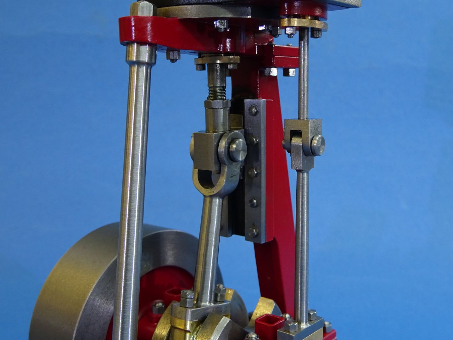
| 976 forum posts 805 photos | Last Year I started a thread about designing and building a Steam engine a got the usual excellent feedback. It's here. The basic idea was I wanted to build an engine that could do real work (even if it never does!) and I wanted to design it myself (with much help from books, plagiarism of real designs and advice from experts) Then the Day Job went mildly insane and over half a year disappeared However, things have eased up and I've now got the design to the point where I can start to make things. I've designed it in OnShape and if you have an OnShape account (free if you only do public designs) you can see it here.. I've tried to do the design very 'parametric' which means that you can adjust a few variables and all will magically reshape itself. There are limits, naturally, I I would probably do it all rather differently if I was to start the process having a clue. Which I did not! Here are the drawings as they stand at the moment. They aren't engineering quality and a lot of things like fastenings aren't included, but I think the overall structure is there. Comments and critiques welcome. The Overall Engine
Cylinder Details
Crank and Piston
Valve Gear
Frame
I'll continue these posts with my build plan and actual build progress (yes I've started!)
Iain |
| Iain Downs | 21/11/2018 04:42:09 |
| 976 forum posts 805 photos | Build Plan Here's what I have in mind at the moment. What I've worked out so far, anyway.
Crankshaft, Crank Case and Main Bearings Shaft 20mm Silver Steel, Journals 12x35 mild steel. Fix shaft with Loctite 638, pin through with (4mm?) steel. Bearings cast iron, split pair, split in two and loctite together, bore to 20mm and heat to release (4 parts). Frame Mild steel (squared and milled to size already!) bolted together. bearings set in place and lapped to a running fit with a spare bit of silver steel. I intend to bolt a counterweight to the flat end of the journal but I've not worked out size and shape yet. It will involve integration The drawings don't show oil channels for bearings, but I will add those in. Cylinder and Caps I'm thinking this would be one big bit of cast iron with the two end caps cut off and machined separately, though I may go for separate caps made of mild steel. This is the most complicated piece of work I think, though I've already has some advice from Richard Gribbins (Hope I spelt your name right, Richard) on how to do some hard parts. Piston to Big End Not sure if I will make the big end bearings from cast iron or bronze, but the rest is steel. I'm also not sure if I should assemble the rods and joints from components and silver solder or try and machine out of whole steel. Most likely I will solder - the machining is probably too much. Frame Connect the Crank to the cylinder. I'm thinking of using stainless for the support struts for the shinyness, even though it costs a bit more. Not quite sure how to finished the model off, paintwise. I did think of brass for the supports struts, but that's very pricey (and I'm not much of a one for polishing). At this point I should be able put the whole thing together and make sure that it runs smoothly. Valve Gear Just one direction to start with. I'll put some reversing gear in if I get the easy stuff to work. Most of this mild steel, I think, though not sure of material for the eccentric bearing. I expect to get the crank stuff done in the next few weeks and hopefully, the cylinder bits done by year end. It depends on the dreaded day job and, of course, how many times I have to throw bits away and start again. Any corrections, warnings or other feedback is most welcome.
Iain |
| JasonB | 21/11/2018 08:02:03 |
 25215 forum posts 3105 photos 1 articles | As few thoughts after having a quick look. Cylinder - I would make the ports a bit deeper to reduce the angle of the passages and try to get the passage area equal to the port if you want it to do work. Exhaust could do with being larger as by the time you have screwed some pipe into there you won't have that large a bore so will be restriction flow, maybe a flange screwed to the outside if you can't fit a larger threaded hole in. If it is going to work then mill away a lot of that cast iron to reduce the mass if you don't want a bucket full of condensate and lag the void, drain cocks would be needed too. It will need a large boiler too. Crank/piston - You don't have anything to guide the cross head so will get a lot of sideways forces that will soon wear glands and the cylinder bore. Either add a trunk guide, single guide to one side or guides both sides. Cross head joint looks quite spindly for the size of engine, there is not a lot of metal around the 8mm pin. Valve - Thread the rod and have an adjustable nut, that T piece at the end will not allow for setting up the valve for equal movement. Like the cross head you have nothing to guide the valve, either extend it into a hole/bush in the top of the valve chest or have a bracket from underneath to guide it. No sign of a stuffing gland to seal the rod. Joint between rods looks weak. Frame - I would fix the lower bearing halves from below with counterbored cap heads, that way when you take the caps off they will stay in the same position so all your lapping won't be wasted. This will also allow the tightness of the two halves to be adjusted without the whole lot moving about Or have steel blocks with turned bronze bearing shells
Edited By JasonB on 21/11/2018 08:07:03 |
| fizzy | 21/11/2018 08:41:28 |
 1860 forum posts 121 photos | As per what Jason has said, without a crosshead guide it will bind up and not run. Make the port geometry bigger if space allows as the restriction will impact on torque. The D valve eccentric rod has to be adjustable or you will never get it to run at its best. Lots to think about. What are your plans for the boiler - going to be big! Good luck. |
| Iain Downs | 21/11/2018 14:40:47 |
| 976 forum posts 805 photos | Thanks Jason and Fizzy.
Can I just check what you mean by some of these items - as I may have said 'me ignorant - not know engineering'! Cylinder when you say make the ports deeper, do you mean that the bit that comes down from the valve surface should be deeper (blue), or that the angled port should be steeper (black), by which I mean the gap from cylinder to surface should be larger.
My guess is you mean black? I've found that Metals4U have 100mm cast iron rounds for £15 per 100 mmm which is somewhat cheaper than I can get a 85x75 bar (which was my intent), so I'm thinking of getting a round and changing the design to suit. That would mean cutting a LOT of iron out but doable. I guess what you're saying is the iron needs to stay hot rather than absorbing the heat which is why we make it thinner. I can do that, though doing so starting from a bigger round will take a log longer with my X1 mill. I saw that the 5A (One of my sources) has drain taps, so I guess I need to add that to the design. I take your comments on the guide. I was wondering about that. What sort of force are we looking at? I've got quite a lot of linear slides like these, but they're quite light. Get your point on mounting bearings. I was wondering about using shims under a plate that attaches to the eccentric bearing for valve adjustments. And I've read that the pressure on the outside of the D holds it against the slide so no additional guide required. I will worry about the boiler once I have this made! I will test it will air to start with, but I've been offered test boilers to take it further. One thing at a time - this is more than ambitious for now! Iain Iain
|
| Neil Wyatt | 21/11/2018 14:57:22 |
 19226 forum posts 749 photos 86 articles | This blog might help with machining the cylinder. www.model-engineer.co.uk/forums/postings.asp?th=36393 Neil |
| JasonB | 21/11/2018 15:16:26 |
25215 forum posts 3105 photos 1 articles | Or This thread
Make the blue port deeper, infact as you have plenty of cylinder cover overlap you could make the top notches go a bit further towards the edge and then just come straight down with the passages. It is more to do with the steam hitting a cold cylinder when you start running, the cold metal will make the steam condense robbing it of energy and filling your cylinder with water. by removing metal to leave a thinner wall and flanges at the end there is less metal to heat up and the space can be lagged to further reduce heat loss. I don't think those guides will be upto it but you can make your own by milling a slot in some steel and screwing overlapping plates each side to make a kind of Tee Slot
Shim would do it but a bit of a faff to keep undoing screws and adding more or less shim until you get it right. With a threaded rod you just pull the pin and turn the rod then pop the pin back in place.
Yes the steam/air pressure will hold the valve to the port face but the sideways action of the eccentric will soon wear the gland. Don't underestimate th e amount of steam or even air an engine this size will need, I should think at least a 6" vertical boiler if not 8" will be needed to play with it. and a 12-15cfm compressor if you don't want it running non stop
|
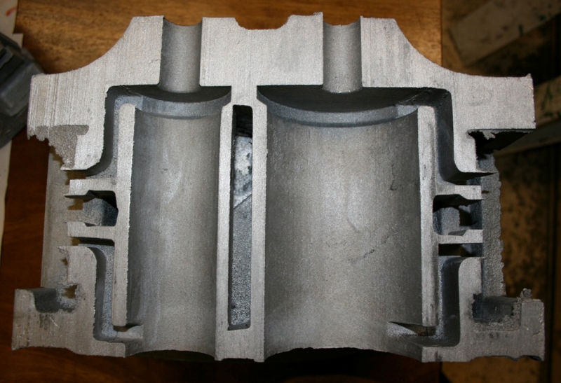
| JasonB | 21/11/2018 15:46:09 |
25215 forum posts 3105 photos 1 articles | If you don't have a rotary table then bore the cylinder and maybe add a round flange on the top end. Round or square stock will do
Mill 3 faces to leave say a 5mm wall thickness
Then mill the "curve" as a series of facets
File to blend if the fancy takes you and there you have a cylinder. You will also end up with a 60mm wide portface so can make your valve chest that width which will help to reduce waste volume inside it.
|
| Iain Downs | 21/11/2018 19:12:14 |
| 976 forum posts 805 photos | Thanks, again. I do have a rotary table. For the eccentric, if I put a thread on, surely the minimum adjustment is going to be half a turn - say .03 - 0.4 mm. Isn't that a bit clumsy when the ports are only 4 or 5 mm wide? On the ports, I'd originally had a stepped design with the port quite deep and then an entry at right angles for the steam to come out at the end of the cylinder and then a small distance down the face to the cylinder (if you see what I mean). I was advised to switch to an angled passage which is what you see in the current drawing. Have I got your intent right? More of a dogleg? I have to say that the machining is easier for that layout! Lovely engine btw - gives me a finish to aim for ...
Iain |
| JasonB | 21/11/2018 20:17:06 |
25215 forum posts 3105 photos 1 articles | Use a metric fine pitch or 40tpi and you will get 0.25 increments which seem to have been OK for model engineers for decades, you get more variation that that when say a traction engines boiler expands and alters the distance between cylinder and crankshaft. If you want finer adjustment then don't use a central bar shaped nut , instead have a nut and locknut either side of the valve then you can get infinite adjustment.
I think angled passages are more of a model engineering thing for when the passages are not cast in as you can't easily drill round corners. There is the argument that the angled route gives a slightly smoother route but if the passages are large enough it won't make much difference. have a look at this 1/2scale Burrell cylinder from Little Samson Models which has the same shape passages as the full size and they are not angled. The Dogleg just makes for easier drilling, you are very close to the port face on your drawings and it would not take much for the drill to break through so even just steepening the angle will help.
|
| geoff walker 1 | 22/11/2018 15:45:53 |
| 521 forum posts 217 photos | Hi Iain, I have been looking at your plans. This engine is similar to one I made last year. Could I make the following suggestion regarding cross head design which you may wish to consider. Your first drawing shows 2 cross bars which support the cylinder block. Why not replace this with a plate across the top. This plate would have a hole in the centre for the piston rod guide. The top of the piston rod guide would locate in the bore of the cylinder and that would of course register the position of the cylinder. The under side of the plate would need a female register turning which truly concentric with the hole in the centre. The cross head guide is made from square stock turned round for most of it's length. On the top of the cross head you would need a male register to match the one in the plate. Here a two pictures from my picture flle, Jepson Engine. Geoff
|
| Iain Downs | 24/11/2018 12:13:06 |
| 976 forum posts 805 photos | As usual, thanks for the feedback. Geoff, I like the idea of switching to a plate and it's something I'd considered, Having to add a guide makes this more appealing. As I understand it, you have a cylinder whose bottom hole is s slidefit for the piston ron and the top has a registration plate which fits into the underside of the plate. How does the gland get fitted? Is that what the holes either side of the top of the support are for. Jason the sketch below is (roughly) what I had in mind originally. And a lot easier to build than angled ports!
A question: I've been trying to minimise the amount of space in the passages and 'closed' cylinder. I'm not sure I know why, but I suspect an early dabbling with car engines has something to do with this. Also, there is less 'unused' steam to exhaust with smaller / shorter ports than with wider longer ones and more space in the cylinder at the end of the cycle. I read in one of my books that 4% ish was right for a medium speed engine, and whilst I've not tried to measure that, I have tried to keep that space down. The question is, 'Am I wrong about this?' - fully expecting the answer, 'yes you are!'. I've been off ill for the last few days, so not even look at the computer let alone attempted a cold dank shed with smoking metals, but today or tomorrow I may brave it! MY Loctite 638 arrived today so I have no material excuse to avoid finishing the crank. Iain |
| Iain Downs | 24/11/2018 15:38:21 |
| 976 forum posts 805 photos | This is the proper version of what I have in mind now (still some bits missing, but it's close). I can carve it from a 90mm cast iron round, I had in mind to finish the bottom of the ports with my newly acquired ball nose carbides to get them smooth.
|
| JasonB | 24/11/2018 16:38:05 |
25215 forum posts 3105 photos 1 articles | Just got in from a day out so will look at the cylinder later.
For a trunk guide I would put a rough hole of say 18mm through some 25mm bar and then silver solder that to some 6mm plate. Then hold by the 25mm diameter to skim the face of the plate down to 5mm thick and at the same setting open up the hole with a boring bar to say 20 or 22mm. This will ensure you have across head and cylinder mounting surface true to each other. lap the bore then mill the notches out of the side to give access to the cross head pin. You still want a cylinder cover so on one side of that have the 2mm spigot that located the cylinder and on the bottom make the spigot that takes the gland a good snug fit in your trunk guide so they are concentric when assembled
|
| Iain Downs | 24/11/2018 18:57:30 |
| 976 forum posts 805 photos | Thanks, Jason. I get the basic idea of the mechanism (I think), but I don't quite get how it stops the piston rod moving. Unless there is a mechanism which clamps onto the outside of the notch that's on the outside of the cylinder. Also, and my apologies, I sometimes get a bit stuck on the technical terms. I guess the cross head is where what I call the piston rod (connects to the piston) joins the con rod (joins to the crank. I'm looking at using Geoff's idea of a plate as a bottom cylinder cover, but I don't want to mill out huge amounts of metal to make a gland spigot. I was wondering about making the guide (trunk or otherwise) and the gland separate to the cap and then bolting on (with suitable registration cuts of course. What do you think?
Iain |
| JasonB | 24/11/2018 19:16:00 |
25215 forum posts 3105 photos 1 articles | looking at the latest cylinder drawing the biggest issue I can see is that the valve face is going to be too narrow by the time you have the sides of the valve and the thickness of the valve chest walls you will be hanging over the edge. Having said that your ports do seem rather large for this sort of size engine. You could safely come down from 25mm wide to 20mm width then have the exhaust 8mm across, 4mm between ports and 4mm inlets. This is a similar sort of size to the Stuart No1 of which many have done real work. This would give you a valve cavity of 20mm wide x 16mm high, make the overall size of the valve 28 x 28. If we then said 1mm clearance each side of the valve and 10mm wall thickness for the valve chest then that would give a 30mm cavity in the chest and 50mm overall width. You could also happily reduce the cylinder wall thickness down to 5mm from 7 mm giving a 30mm radius. Finally take the flanges to 5 or 6mm thick to give the studs a bit more meat to bit into as you only have four of them Finally bring the passages in a little closer to the cylinder bore so you get a decent width seal to teh outside edge, reducing from the 5mm to 4mm will also help with that. |
| JasonB | 24/11/2018 19:47:11 |
25215 forum posts 3105 photos 1 articles | So with all the bits mentioned above plus chopping the cylinder down to 82mm overall height you get something like this
|
| Iain Downs | 24/11/2018 20:03:51 |
| 976 forum posts 805 photos | Bloody hell, Jason, do you have a direct brain link to a 3D modelling tool?!!!! It would take me an hour to draft that! (well it did actually - or my bad version!). The port sizes are taken directly from a 5A. As my may recall I had a go at working out the science on this, but gave up and just copied something that worked - an excellent engineering approach IMHO. I say directly - I converted 32nds to mm, but close enough. I shall have a look at this tomorrow - too late now for thinking! Many thanks again,
Iain |
| Iain Downs | 24/11/2018 21:54:55 |
| 976 forum posts 805 photos | OK. This really is enough for tonight! Your advice (particularly the port face) is well taken, though I've been stubborn about the port spacing (not the width). I'm still not sure either how to best model or to machine the drain spigots, but that's manageable. Here's the rest.
Iain
|
| JasonB | 25/11/2018 09:12:25 |
25215 forum posts 3105 photos 1 articles | What are you drawing it with? On my Alibre one I selected the inner face of the flange, drew a 10mm rectangle and then extruded that 8mm, then put a 5mm radius on the corners, drilled hole and cut extrude to do the counterbore out from the face of my block. As for machining something like this. Assuming you will have wood or sheet metal cleading it does not have to look perfect.
|


 .
.


.jpg")


Please login to post a reply.
Magazine Locator
Want the latest issue of Model Engineer or Model Engineers' Workshop? Use our magazine locator links to find your nearest stockist!
Sign up to our Newsletter
Sign up to our newsletter and get a free digital issue.
You can unsubscribe at anytime. View our privacy policy at www.mortons.co.uk/privacy
Latest Forum Posts
- hemingway ball turner
04/07/2025 14:40:26 - *Oct 2023: FORUM MIGRATION TIMELINE*
05/10/2023 07:57:11 - Making ER11 collet chuck
05/10/2023 07:56:24 - What did you do today? 2023
05/10/2023 07:25:01 - Orrery
05/10/2023 06:00:41 - Wera hand-tools
05/10/2023 05:47:07 - New member
05/10/2023 04:40:11 - Problems with external pot on at1 vfd
05/10/2023 00:06:32 - Drain plug
04/10/2023 23:36:17 - digi phase converter for 10 machines.....
04/10/2023 23:13:48 - More Latest Posts...
- View All Topics
Support Our Partners


Shopping Partners
Subscription Offer

Latest "For Sale" Ads
- Reeves** - Rebuilt Royal Scot by Martin Evans
by John Broughton
£300.00 - BRITANNIA 5" GAUGE James Perrier
by Jon Seabright 1
£2,500.00 - Drill Grinder - for restoration
by Nigel Graham 2
£0.00 - WARCO WM18 MILLING MACHINE
by Alex Chudley
£1,200.00 - MYFORD SUPER 7 LATHE
by Alex Chudley
£2,000.00 - More "For Sale" Ads...
Latest "Wanted" Ads
- D1-3 backplate
by Michael Horley
Price Not Specified - fixed steady for a Colchester bantam mark1 800
by George Jervis
Price Not Specified - lbsc pansy
by JACK SIDEBOTHAM
Price Not Specified - Pratt Burnerd multifit chuck key.
by Tim Riome
Price Not Specified - BANDSAW BLADE WELDER
by HUGH
Price Not Specified - More "Wanted" Ads...
Get In Touch!
Do you want to contact the Model Engineer and Model Engineers' Workshop team?
You can contact us by phone, mail or email about the magazines including becoming a contributor, submitting reader's letters or making queries about articles. You can also get in touch about this website, advertising or other general issues.
Click THIS LINK for full contact details.
For subscription issues please see THIS LINK.
Digital Back Issues


Donate

 Register
 Log-in
Model Engineer Magazine
- Percival Marshall
- M.E. History
- LittleLEC
- M.E. Clock

ME Workshop
- An Adcock
- & Shipley
- Horizontal
- Mill

Subscribe Now
- Great savings
- Delivered to your door

Pre-order your copy!
- Delivered to your doorstep!
- Free UK delivery!
All Forum Topics > Stationary engines > Steam Engine Number One