Forum sponsored by:

problem with rotary table
| geoff walker 1 | 04/10/2018 17:31:22 |
| 521 forum posts 217 photos |
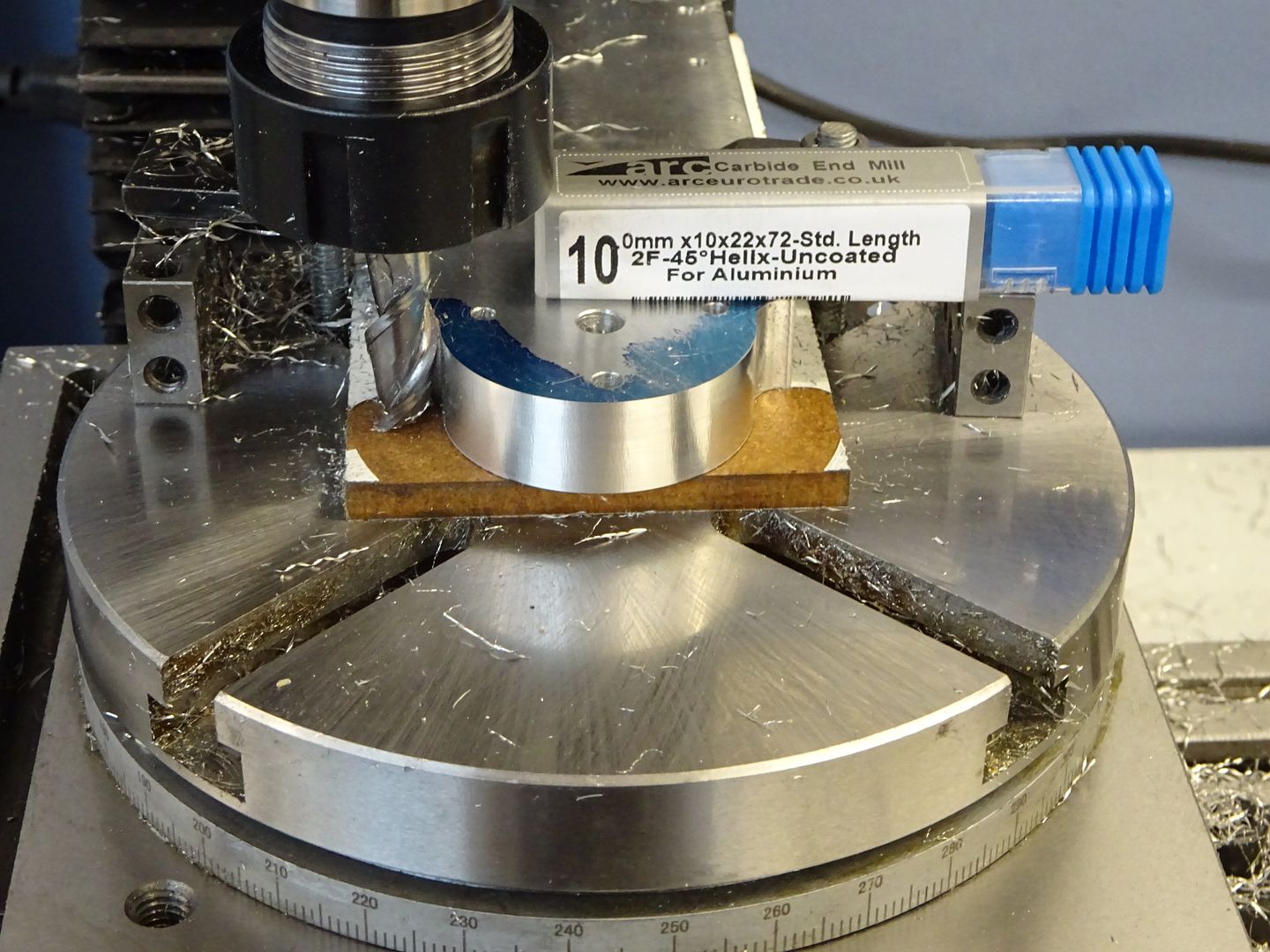
Today I was milling a curve in the aperture of engine frame. My problem is that with the set up I had when I tightened the nuts the table became very stiff and it was really difficult to turn the handle on the table. As you can see i have brass tee nuts, 4mm thread, which accept 4mm studding. the bar which goes across the frame is 1/4" m.s. The more I tightened the nuts the stiffer the table. It feels like the tightening is distorting the table and thus creating unwanted friction between the table and base. That to me is illogical but I'm stumped for any other answer. Any thoughts Guys |
| John Rudd | 04/10/2018 17:35:43 |
| 1479 forum posts 1 photos | If you place a clock gauge on the rotab and with the base on the mill as a reference, watch the clock as you tighten the clamps....if the pointer moves.... |
| SillyOldDuffer | 04/10/2018 17:50:09 |
| 10668 forum posts 2415 photos | I can't account for that, but two thoughts:
Hope it's something trivial! Dave
|
| JasonB | 04/10/2018 18:31:11 |
 25215 forum posts 3105 photos 1 articles | Where do you have the packing pieces that are lifting the work off the table? you are less likely to distort the table if they are directly below the points where your 1/4" clamping plate is placed. I would usually put something over the whole area that won't hurt the cutter such as 6mm MDF or a bit of rigid PVC sheet.
Edited By JasonB on 04/10/2018 18:33:26 |
| IanT | 04/10/2018 21:31:41 |
| 2147 forum posts 222 photos | Sounds a lot like the same problem that can occur when you tighten the T-nuts too much on a cross-slide Geoff (like a Myford for instance). The answer there (and perhaps to your rotary problem) is to make a sub-table. I have them for my lathes and mills - partly so I can attach things that don't normally fit the holes/slots - but also so I can really tighten work down to them (and sometimes to move work (& table) between machines without disturbing the work setting (by referencing the table). I haven't made any for my rotaries yet - but if I had this problem with one - I think it would the first thing I'd try. They don't have to be anything fancy and are very useful once made. Regards, IanT |
| geoff walker 1 | 05/10/2018 07:35:20 |
| 521 forum posts 217 photos | Hi All Big thank you for all your replies, all of which are really helpful. A little experiment last night revealed that clamping pressure on the outside of the rim causes the table to lock, when it's nearer the centre there is no problem. I set up a dial gauge as John suggested and you see the finger move as the table flexes, not much but enough to tighten it up. It's very frustrating, I'll have a good look at it this weekend. Really like the idea of a sub table, I have one for my lathe cross slide, they are a good idea. It might help to even the load across the table I'll report back on this one. Thanks to all again Geoff |
| geoff walker 1 | 08/10/2018 09:22:07 |
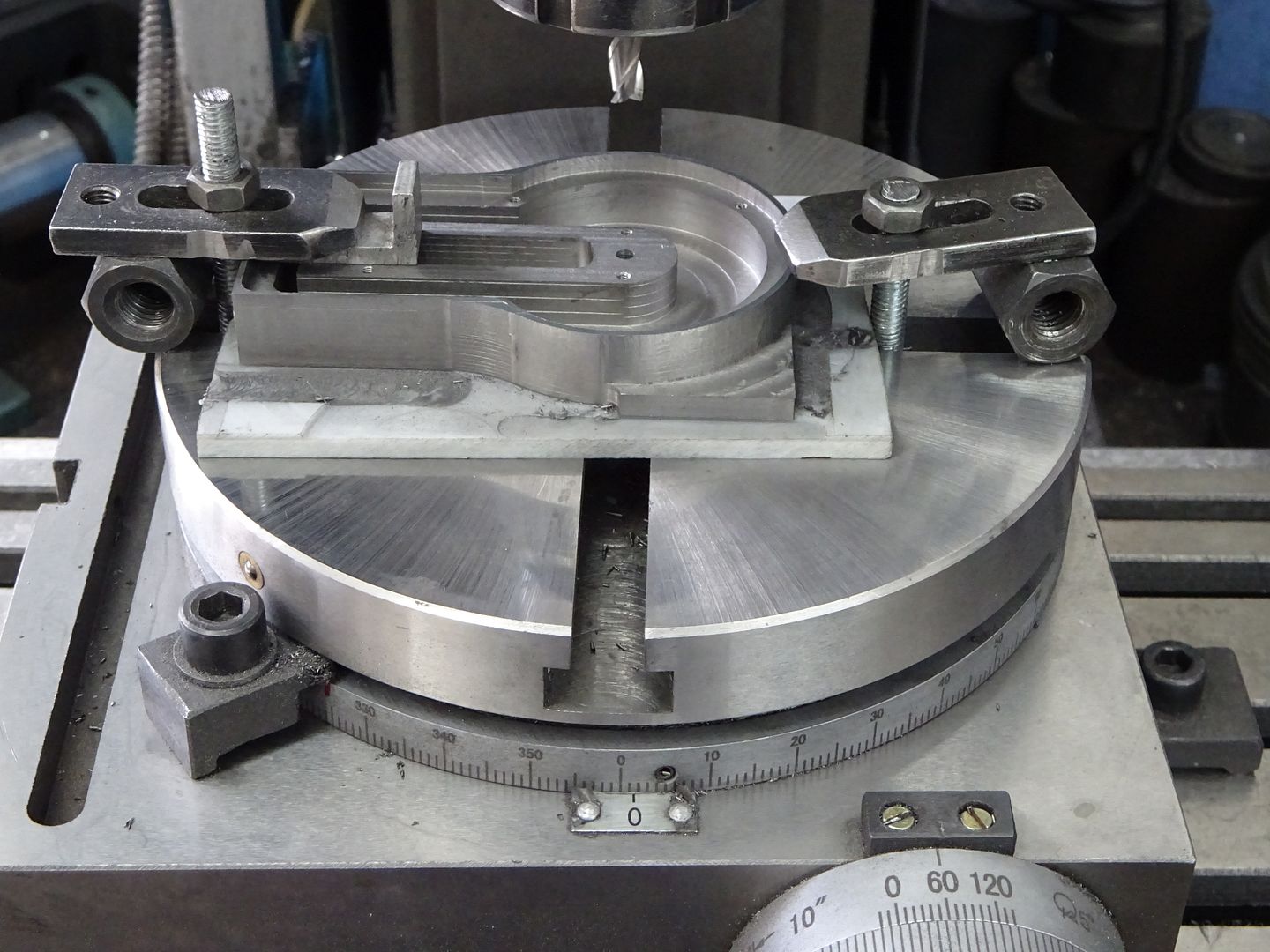
| 521 forum posts 217 photos | Hi All, I have to say I was really disappointed with this little table of mine. I didn't expect to have the problem I had. Having said that it was "cheap as chips" so I suppose you get what you pay for!! Anyway I took Ian T's advice and made a small sub table. This is secured firmly by 4 screws nearer to the centre of the table. The underside of the sub table is relieved 3/4" in from the perimeter so no pressure is applied to the outer rim of the table. No binding or flexing problems now and it should be ok for the work I have planned. Geoff
|
| Ian B. | 08/10/2018 09:30:48 |
| 171 forum posts 5 photos | I now have a similar one to this, bought for the downsizing exercise. I will have to look into this problem as the bits I have used it for so far have been OK. Never thought of this before as I had a pretty chunky one with the larger machine, a Chinese cheapie I hasten to add yet it took all the abuse I could throw at it. Hand on heart that was a fair bit, hangs head in shame. regards Ian
|
| Michael Gilligan | 08/10/2018 09:46:53 |
 23121 forum posts 1360 photos | Glad to see that you've made it useable, Geoff I do remain intrigued as to the original 'failure mode' though ... If you ever dismantle it, perhaps you could take a few photos to show the design, and the finish of any bearing surfaces. Thanks MichaelG.
Edited By Michael Gilligan on 08/10/2018 09:48:33 |
| geoff walker 1 | 08/10/2018 13:27:19 |
| 521 forum posts 217 photos | Hi Ian, Michael, I do remain intrigued as to the original 'failure mode' though ... It's not really a failure as such Michael. The unit is generally well designed the action is very smooth with very little backlash. The problem as I see it is the outer rim of the table has very thin section whereas the inner part of the table has a boss underneath which stiffens it up. If you look at the set up in the earlier photo you can see that the engine frame is bearing down hard on the outer rim. This combined with the upward thrust of the tee nut is causing the rim to flex, not much, but enough to create friction between the table and the base. It's a design fault, if the outer rim was a little thicker I don't think there would be problem. Geoff |
| Michael Gilligan | 08/10/2018 13:38:08 |
23121 forum posts 1360 photos | Posted by geoff walker 1 on 08/10/2018 13:27:19:
Hi Ian, Michael, I do remain intrigued as to the original 'failure mode' though ... It's not really a failure as such Michael. . I was reluctant to use the term, Geoff ... but couldn't think of a better one. < For the defence > Whilst nothing broke, the device failed to perform as required. MichaelG. |
| IanT | 08/10/2018 15:40:33 |
| 2147 forum posts 222 photos | That's a tidy job Geoff - and if it's now working to your satisfaction - I wouldn't worry further about it.
Regards, IanT |
| Pete Rimmer | 08/10/2018 17:46:31 |
| 1486 forum posts 105 photos | Posted by Michael Gilligan on 08/10/2018 09:46:53:
Glad to see that you've made it useable, Geoff I do remain intrigued as to the original 'failure mode' though ... If you ever dismantle it, perhaps you could take a few photos to show the design, and the finish of any bearing surfaces. Thanks MichaelG.
Edited By Michael Gilligan on 08/10/2018 09:48:33 If bolting a part to the table makes it flex, then either the table or the part isn't flat. I'd be bluing the table up to see if it was pringle-shaped first off. |
| IanT | 08/10/2018 18:18:53 |
| 2147 forum posts 222 photos | A good point Pete - but even if the table is perfectly flat - the work usually isn't - and that's before you start applying clamps, straps & packing to attach that part to the table (or cross-slide etc) being used. Quite apart from the other benefits of using sub-tables - a lot of machinery designed for hobby use just isn't that "heavy-duty" in nature - sub-tables can help rectify this deficiency and reduce the possibility of causing damage (like to the T-slots for instance). Regards, IanT |


Please login to post a reply.
Magazine Locator
Want the latest issue of Model Engineer or Model Engineers' Workshop? Use our magazine locator links to find your nearest stockist!
Sign up to our Newsletter
Sign up to our newsletter and get a free digital issue.
You can unsubscribe at anytime. View our privacy policy at www.mortons.co.uk/privacy
Latest Forum Posts
- *Oct 2023: FORUM MIGRATION TIMELINE*
05/10/2023 07:57:11 - Making ER11 collet chuck
05/10/2023 07:56:24 - What did you do today? 2023
05/10/2023 07:25:01 - Orrery
05/10/2023 06:00:41 - Wera hand-tools
05/10/2023 05:47:07 - New member
05/10/2023 04:40:11 - Problems with external pot on at1 vfd
05/10/2023 00:06:32 - Drain plug
04/10/2023 23:36:17 - digi phase converter for 10 machines.....
04/10/2023 23:13:48 - Winter Storage Of Locomotives
04/10/2023 21:02:11 - More Latest Posts...
- View All Topics
Support Our Partners


Shopping Partners
Subscription Offer

Latest "For Sale" Ads
- Reeves** - Rebuilt Royal Scot by Martin Evans
by John Broughton
£300.00 - BRITANNIA 5" GAUGE James Perrier
by Jon Seabright 1
£2,500.00 - Drill Grinder - for restoration
by Nigel Graham 2
£0.00 - WARCO WM18 MILLING MACHINE
by Alex Chudley
£1,200.00 - MYFORD SUPER 7 LATHE
by Alex Chudley
£2,000.00 - More "For Sale" Ads...
Latest "Wanted" Ads
- D1-3 backplate
by Michael Horley
Price Not Specified - fixed steady for a Colchester bantam mark1 800
by George Jervis
Price Not Specified - lbsc pansy
by JACK SIDEBOTHAM
Price Not Specified - Pratt Burnerd multifit chuck key.
by Tim Riome
Price Not Specified - BANDSAW BLADE WELDER
by HUGH
Price Not Specified - More "Wanted" Ads...
Get In Touch!
Do you want to contact the Model Engineer and Model Engineers' Workshop team?
You can contact us by phone, mail or email about the magazines including becoming a contributor, submitting reader's letters or making queries about articles. You can also get in touch about this website, advertising or other general issues.
Click THIS LINK for full contact details.
For subscription issues please see THIS LINK.
Digital Back Issues


Donate

 Register
 Log-in
Model Engineer Magazine
- Percival Marshall
- M.E. History
- LittleLEC
- M.E. Clock

ME Workshop
- An Adcock
- & Shipley
- Horizontal
- Mill

Subscribe Now
- Great savings
- Delivered to your door

Pre-order your copy!
- Delivered to your doorstep!
- Free UK delivery!
All Forum Topics > Beginners questions > problem with rotary table