Forum sponsored by:

Myford super 7 Positioning servo's on Spindle and main infeed
Complete rebuild and conversion.
| Andrew Davies 4 | 25/09/2018 09:38:50 |
 49 forum posts 56 photos |
I am a drives and controls engineer, I have applied this knowledge to customer with machine tools all my working life. I AM NOT A MACHANICAL ENGINEER, but have a reasonable understanding and a real interest.
I have recently purchased a Myford Super 7 to restore and convert the spindle and main feed screw to CNC with positioning servo’s on both axis. I am fitting a 16mm dia, 5mm pitch ball screw to replace the main screw, this is the axis that will have one of the servo’s.
As a learning process, I restored a basic lathe and fitted a vector spindle, just to understand the mechanics and understand what I needed from the next lathe to deliver the quality I needed. YouTube - **LINK** When the Myford is finished, I will sell the first lathe.
The main use of the lathe will be to produce clock gears and pinions, but also parts for my vintage motorbike.
The lathe is stripped and the bed is away being ground. I am going through each assembly and restoring as I go along.
I selling the clutch and counter shaft, motor, all pulley’s including spindle pulley, rack, screw and apron and all other bits that I do not need. Some bits have all ready been sold.
My first question is the top and bottom slides. There is backlash, I think it will be the nuts as these are made of an alloy. Where would I get 2 bronze nuts to replace the original nuts? I understand that backlash is not always a problem as it can be overcome with good practice, but I want to reduce it to a minimum
I am tempted to replace these primitive screw’s with rolled ball screw’s and include a locking mechanism on each axis as the ball screw will not hold position as it does not have enough friction. This would allow servo’s to be added on these slides. But this may be a job for latter.
I have many pictures I have taken along this journey and I will have many more before I reach the finish line. I am not sure about the norm of this forum but I am happy to share them. I would welcome the answer to the above question.
(Due to my lack of knowledge about this forum, I posted this elsewhere. I have decided to create a new thread).
Edited By Andrew Davies 4 on 25/09/2018 09:42:08 |
| Andrew Davies 4 | 25/09/2018 10:02:03 |
49 forum posts 56 photos | Another question. The S7 is designed to use a tool holder about 8mm square. I want to use a 10mm tool holder. As I am doing so much work I am happy to mill 2mm from the bottom of the main tool holder that sits on the compound slide. I am going to get the 3 saddles ground during the rebuild, hence the 2mm may vary to bring the tip height to the exact position. Can anyone see a problem with doing this?
Thanks Andrew |
| Hopper | 25/09/2018 11:55:44 |
 7881 forum posts 397 photos | Common practice to mill a bit off the bottom of the tool holder. My ML7 was made to take 3/8" tool bits or smaller so I had to knock 20 thou or so off it when i converted to modern 10mm insert tooling. Did it in situ with an end mill cutter held in the lathe chuck and suitable packing under the toolpost. If you are getting the carriage and cross slides reground, you may drop the tool holder sufficiently in the process anyway and not have to bother. |
| SillyOldDuffer | 25/09/2018 12:02:05 |
| 10668 forum posts 2415 photos | Comments withdrawn - I was against grinding the toolpost but then read Hopper's post and realised I was being over cautious... Edited By SillyOldDuffer on 25/09/2018 12:05:11 |
| JasonB | 25/09/2018 12:05:58 |
 25215 forum posts 3105 photos 1 articles | Why not just make an extra toolpost or even clamp the tool with packing straight onto the topslide like Myford owners did before they got a 4-way or QC toolpost. the bigger tooling is stiffer when you get a situation where you need a lot of tool overhang such as working with tailstock support or around the edge of a large diameter such as a flywheel not just when you want to take a heavy cut. Edited By JasonB on 25/09/2018 12:09:02 |
| KWIL | 25/09/2018 12:28:39 |
| 3681 forum posts 70 photos | If you are regrinding the carriage you must remember to also grind the surface where the apron fits, otherwise the leadscrew alignment will be too low. Similarly if the bed is reground. |
| JasonB | 25/09/2018 13:06:51 |
25215 forum posts 3105 photos 1 articles | Or just mount the new ballscrew nut to take into account any loss of height. |
| blowlamp | 25/09/2018 13:13:59 |
 1885 forum posts 111 photos | Buy a kit from cncyourmyford.com
Martin. |
| Andrew Davies 4 | 25/09/2018 14:20:13 |
49 forum posts 56 photos | Many thanks for all your comments. The apron will no longer be there. I am making a bracket to mount the ball nut to the underside of the bottom saddle. Due to this, I am going to mount the ball screw and both end bearings and then measure up bracket. 20 thou is only 0.5mm, I have a difference in tool holders of about 2mm. Have I missed something? Andrew
|
| Andrew Davies 4 | 27/09/2018 09:38:20 |
49 forum posts 56 photos |
I compliment CNCmymyford for the work they have done, but I think I can have more fun doing it myself, complete for a much lower price, and have a better solution. This is not arrogance; it is just that this is what I have done for 30 years. Please note the operative word is think, as I have not seen the full specification of cncmymyford. Issues I have:- It still uses an asynchronous motor, albeit with a cheap encoder. Not sure you can position the spindle with full torque No dedicated HMI No real time CNC as it is running on a laptop Not a big fan of stepper motors. …………..
|
| Muzzer | 27/09/2018 12:33:58 |
 2904 forum posts 448 photos | Posted by blowlamp on 25/09/2018 13:13:59:
Buy a kit from cncyourmyford.com Martin. Wow. £3300 plus painting and a lot of fitting. Pigs and lipstick come to mind. For that cost plus the cost of a Myford you could probably pick up a proper CNC machine and spend your time bringing it back to life, with some likelihood of ending up with a decent machine. Murray |
| Andrew Davies 4 | 27/09/2018 14:00:56 |
49 forum posts 56 photos | Hi Is that Muaray from Kenilworth?? Andrew |
| Muzzer | 27/09/2018 14:14:03 |
2904 forum posts 448 photos | No, that'll be Murray from Lancashire (currently) - Lytham St Annes (posh name for Blackpool). Murray |
| Nick Hulme | 01/10/2018 23:31:20 |
| 750 forum posts 37 photos | If you replaced cross slide and top slide standard screws with ball-screws you could use a harmonic drive gearbox to link a handle to the screw, that would eliminate the need for a lock or brake. |
| Andrew Davies 4 | 02/10/2018 07:05:00 |
49 forum posts 56 photos | Hi This is true, and may be the way to go. Many thanks Andrew |
| Andrew Davies 4 | 02/10/2018 07:12:23 |
49 forum posts 56 photos |
|
| John Haine | 02/10/2018 07:38:16 |
| 5563 forum posts 322 photos | By top and bottom slides I suppose you mean the cross and top (or compound) slide? For CNC you have no need of a topslide any more. You can then make a properly rigid tool post that fits the cross slide. This makes it possible to used indexed tool holders and properly apply tool offsets.
The cross slide screw is best replaced with a ballscrew, it is very hard to get rid of backlash with a normal nut, and backlash on the X slide is a real pain - for example when cutting tapers. Depending which S7 you have you may need to find a small diameter ballscrew for the X slide to fit the available hole - my conversion was of a power X feed 9pxf) machine that uses a larger feedscrew so I was able to use a 12mm screw supported only at the outboard end. It isn't essential to have a ballscrew on the main Z feed ("leadscrew" Why are you fitting a servo to the spindle? Normal practice is to have a spindle sensor, either 1 per rev for Mach 3 or a multi-slot sensor for better systems such as LinuxCNC, but to use a standard drive system. As long as the controller knows where the spindle is it can control the tool position to suit at least for screw cutting. If you are thinking of using this for dividing, I think you're better off having a separate digital division head. Most readily available CNC controllers expect a standard drive spindle, not a servo positioned one. These days it is recommended to have a separate motion controller between the controlling PC and the servos/steppers (by the way please note that you DON'T use an apostrophe when an "s" is indicating a plural). This interfaces to the PC using USB or Ethernet, and actually generates the real-time control signals - I can't recall exactly but I assume that's what cncyourmyford does. With this approach you can use a laptop because all the real-time stuff happens in the controller. Hope this helps - I first converted my S7 nearly 10 years ago and have made a number of improvements since and it works very well.
|
| Andrew Davies 4 | 02/10/2018 12:31:56 |
49 forum posts 56 photos | Hi By fitting a servo on the spindle I have infinite position capability, For cutting different clock gears or threads this is perfect, all gears will be removed and the servo is on the end of the ball screw.. Spindle and additional axis will interpolate. I will be using a position control integrated into one of the dives with PLC (IEC1131) capability, this will talk to the second drive over SERCOS, the HMI will both read and enter variables. I want the CNC to be real time, hence not from a lap top. The solution I will be using is MLD by Bosch Rexroth. I want to fit a high speed spindle for the gear cutting at a later date; this allows a great deal of flexibility.
P.S. I am and engineer, hence grammar is not perfect. Many thanks Andrew Edited By Andrew Davies 4 on 02/10/2018 12:38:19 Edited By Andrew Davies 4 on 02/10/2018 12:43:07 |
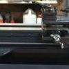
| Andrew Davies 4 | 03/10/2018 12:45:39 |
49 forum posts 56 photos | Just finished the final bit of painting. Start propper engineering in the morning |
| blowlamp | 03/10/2018 13:14:35 |
1885 forum posts 111 photos | Posted by Andrew Davies 4 on 03/10/2018 12:45:39:
Just finished the final bit of painting. Start propper engineering in the morning
Sorry to say that looks like a crappy regrind you got there. Did they skim the feet first and also do the vertical shears & undersides? Martin. Edited By blowlamp on 03/10/2018 13:21:19 Edited By blowlamp on 03/10/2018 13:22:03 |


 and I haven't fitted one (it's on the to-do-one-day list). If you do use standard nut, the Myford non-pxf nuts are made of mazak alloy as standard and you'd need to make or have made a bronze one - even then you'd be lucky to get a low enough level of backlash. My ballscrew gives about 0.02 mm IIRC. The Myford pxf nuts are hardened steel, but even with those the as-new backlash is ~0.2 mm.
Please login to post a reply.
Magazine Locator
Want the latest issue of Model Engineer or Model Engineers' Workshop? Use our magazine locator links to find your nearest stockist!
Sign up to our Newsletter
Sign up to our newsletter and get a free digital issue.
You can unsubscribe at anytime. View our privacy policy at www.mortons.co.uk/privacy
Latest Forum Posts
- *Oct 2023: FORUM MIGRATION TIMELINE*
05/10/2023 07:57:11 - Making ER11 collet chuck
05/10/2023 07:56:24 - What did you do today? 2023
05/10/2023 07:25:01 - Orrery
05/10/2023 06:00:41 - Wera hand-tools
05/10/2023 05:47:07 - New member
05/10/2023 04:40:11 - Problems with external pot on at1 vfd
05/10/2023 00:06:32 - Drain plug
04/10/2023 23:36:17 - digi phase converter for 10 machines.....
04/10/2023 23:13:48 - Winter Storage Of Locomotives
04/10/2023 21:02:11 - More Latest Posts...
- View All Topics
Support Our Partners


Shopping Partners
Subscription Offer

Latest "For Sale" Ads
- Reeves** - Rebuilt Royal Scot by Martin Evans
by John Broughton
£300.00 - BRITANNIA 5" GAUGE James Perrier
by Jon Seabright 1
£2,500.00 - Drill Grinder - for restoration
by Nigel Graham 2
£0.00 - WARCO WM18 MILLING MACHINE
by Alex Chudley
£1,200.00 - MYFORD SUPER 7 LATHE
by Alex Chudley
£2,000.00 - More "For Sale" Ads...
Latest "Wanted" Ads
- D1-3 backplate
by Michael Horley
Price Not Specified - fixed steady for a Colchester bantam mark1 800
by George Jervis
Price Not Specified - lbsc pansy
by JACK SIDEBOTHAM
Price Not Specified - Pratt Burnerd multifit chuck key.
by Tim Riome
Price Not Specified - BANDSAW BLADE WELDER
by HUGH
Price Not Specified - More "Wanted" Ads...
Get In Touch!
Do you want to contact the Model Engineer and Model Engineers' Workshop team?
You can contact us by phone, mail or email about the magazines including becoming a contributor, submitting reader's letters or making queries about articles. You can also get in touch about this website, advertising or other general issues.
Click THIS LINK for full contact details.
For subscription issues please see THIS LINK.
Digital Back Issues


Donate

 Register
 Log-in
Model Engineer Magazine
- Percival Marshall
- M.E. History
- LittleLEC
- M.E. Clock

ME Workshop
- An Adcock
- & Shipley
- Horizontal
- Mill

Subscribe Now
- Great savings
- Delivered to your door

Pre-order your copy!
- Delivered to your doorstep!
- Free UK delivery!
All Forum Topics > CNC machines, Home builds, Conversions, ELS, automation, software, etc tools > Myford super 7 Positioning servo's on Spindle and main infeed