Forum sponsored by:

Between centres boring bar bit grinding
| Brian O'Connor | 25/09/2017 12:28:57 |
| 74 forum posts 19 photos | I'm about to bore out a cyliinder using a between centres boring bar that uses a 3/16" circular bit. I've never been sure of the correct way of grinding these bits, can anyone offer me some advice please, preferebly with a sketch? B |
| Jon Gibbs | 25/09/2017 12:57:42 |
| 750 forum posts | Hi Brian, Jason kindly linked to this series of 5 schematics a while ago when I was interested in the same question... I hope they help you as much as they helped me. - Thanks again Jason. Jon Edited By Jon Gibbs on 25/09/2017 12:58:27 |
| Clive Foster | 25/09/2017 13:48:31 |
| 3630 forum posts 128 photos | Hi Brian Tool heel clearance is what gets most of us into trouble when it comes to grinding boring tools. Especially with smaller bores. If you have access to a decent CAD program I suggest that you do your own version of Jason's first sketch dimensioned appropriately for your job. Do it at a large scale so you can see exactly whats happening to clearances at the cutting edge and at the heel of the tool. Many folk suggest that the tool tip be set a touch above centre height to win a bit more clearance below the cutting edge. Something that a large scale drawing will help you assess. Boring tools in general and between centre bars in particular are somewhat less stiff than conventional lathe tooling. Of necessity the cutting edge has to divine its support at considerable distance so on our sizes of work deflection is pretty much a fact of life on all but the very smallest of cuts. Another reason why some folk advocate setting little above centre, the idea being that when deflection occurs the tool comes back to centre height. The smaller the job the harder it gets as slender tools are disproportionately less stiff than fatter ones. As ever no substitute for experience. But it really helps if you start off properly as per Jasons sketches. The detail geometry and tip radius of the cutting edge are essentially the same as that of a left hand lathe tool and need to be appropriate to the material being worked and finish required. Large tip radii tend to promote pushback and deflection so use the smallest radius you can commensurate with the desired finish. Clive. Edited By Clive Foster on 25/09/2017 13:49:03 |
| Martin Kyte | 25/09/2017 13:59:49 |
 3445 forum posts 62 photos | Do make a little holder, piece of bar, correct size holein the end and a grubscrew to nip it up. If you use square bar you get constant registration on the grinding rest. Much better than fingers or pliers. Ignore me if you are already there. regards Martin |
| Fowlers Fury | 25/09/2017 15:16:32 |
 446 forum posts 88 photos | I do appreciate that you already have a between centres boring bar and would therefore be loathe to make another - as was I. But having got into various difficulties, especially trying to measure the radius of cut and then precisely advance the tool, I put it aside. Then built the one designed by Geo Thomas and with the geometry of his boring tool. It was time well spent and probably saved scrapping a big cylinder block casting. The 'bar has been loaned out several times to others who've expressed....ahem..... complete satisfaction
|
| Brian O'Connor | 26/09/2017 09:34:20 |
| 74 forum posts 19 photos | Many thanks for the replies chaps, plus thanks to Jason for the drawings. Martin: A good suggestion, I shall make one immediately. FF: The cylinder I am machining will end up with a 1.5" bore. My boring bar is 3/4" dia, the bit is at right angles to the bar so the bit will end up projecting by 3/8" and hence not very rigid. I will have to make a number of passes at the same setting to ger rid of the spring. With the bit at 45 degrees as in the Geo Thomas design the bit would be 41% longer and hence even less rigid.. |
| Fowlers Fury | 26/09/2017 10:52:43 |
446 forum posts 88 photos | Brian, likewise the bore of the cylinders I was machining had to be 1.5 ± 0.001" and my original b/bar was also 3/4" D. It just wasn't substantial enough, as you acknowledge "not very rigid". The early cuts were causing the bar to flex noticeably - particulalry when entering the bore and thus leading to a 'lip'. The Geo. Thomas one illustrated was 1.25"D and worked very well for those cuts to final, exact size. As he pointed out in his article, the other big advantage of the angled tool is the comparative ease with which you can measure the radius of cut c/f a radial tool where it protrudes below the bar. Perhaps a b/bar of just 50% of the required hole diameter will cause you problems irrespective of tool point geometry? |
| Brian O'Connor | 27/09/2017 09:05:29 |
| 74 forum posts 19 photos | FF: You are right, I should have a more subatantial boring bar but I thought that I would give this one a go before going to the trouble (and expense) of making a larger one that I would probably use only once. I actually don't have a great amount of metal to remove. Unusually the casting was not cored and most of the metal has been removed by successively larger drills and use of a boring head in the mill. Unfortunately the mill does not have sufficient headroom to bore it in one go so I had to attack it from both ends, with the inevitable result of a mismatch in the centre in spite of very careful setting up.. I'm just waiting for the delivery of a diamond wheel so that I can grind the bit to Jason's drawings and give it a go. |
| Fowlers Fury | 27/09/2017 12:07:47 |
446 forum posts 88 photos | Fully understood Brian and sympathies with the situation. If you "don't have a great amount of metal to remove" is it worth considering a double-ended tool in your small diameter b/bar to reduce flexing? The tool would obviously have to be ground to o/a length of the precise final diameter. I've not had to employ the method and can't now find the reference I once had. No doubt others can testify or otherwise as to its effectiveness. |
| mark costello 1 | 27/09/2017 15:47:36 |
 800 forum posts 16 photos | Could You put another hole for the tool bit in another location to gain the range needed? It would be cut and try but it would match up. |
| Brian O'Connor | 27/09/2017 16:26:09 |
| 74 forum posts 19 photos | FF: Oh dear, I've just discovered that my boring bar is too short! I thought that it was a foot long but is actually only 11", which means that with a driving dog on one end it won't clear both ends of the 5¼ inch casting. DOH!! I have just ordered a foot of 1¼ inch bar as per yours but will still have the bit (which can now be a more substantial 6mm dia) going straight across. The reason is that Jason's drawings are for that arrangement and I don't trust myself to shuffle things around by 45º and get it right. But still many thanks for taking an interest in my problem.. |
| JasonB | 27/09/2017 16:46:22 |
 25215 forum posts 3105 photos 1 articles | How big is your tailstock ctr? will that fit down the bore, a fixed one certainly would and gain yoy an inch or two I've had to squeeze my live ctr into a few tight spots while boring, that's a 28mm dia bar for scale
|
| Fowlers Fury | 27/09/2017 17:20:34 |
446 forum posts 88 photos | Brian, may I ask whether you've used a radial tool with a between centres b/bar previously? If you have then presumably you've encountereed the buggeration and calculations needed each time you want to determine how far to advance the tool and then check it's been moved precisely. Even with a tool not protruding from t'other end there's the added difficulty of the open end and how that might affect a micrometer or vernier reading. OK, you could make a smooth surfaced plug but that'd have to be removed and replaced for every measurement. Life is so very much easier with an angle tool as per Geo Thomas and other's designs. However I can appreciate the attractions of just making a radial hole for the tool. Edited By Fowlers Fury on 27/09/2017 17:21:02 |
| Brian O'Connor | 27/09/2017 18:39:30 |
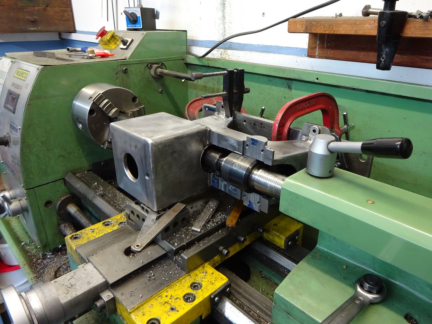
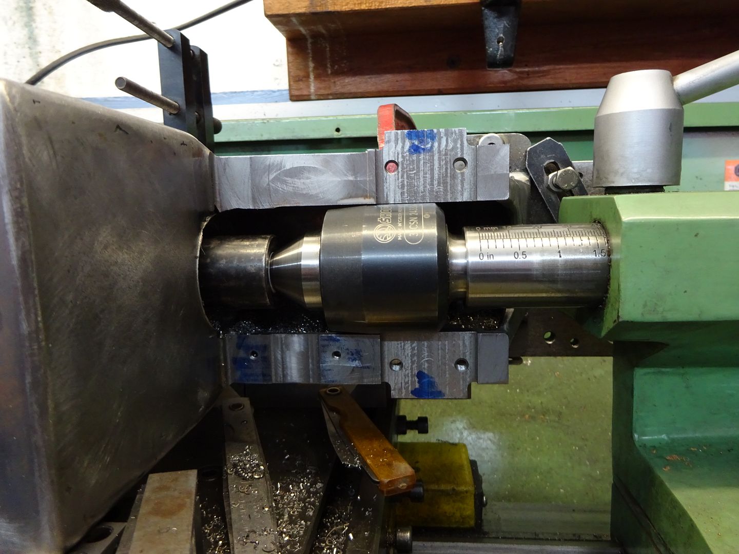
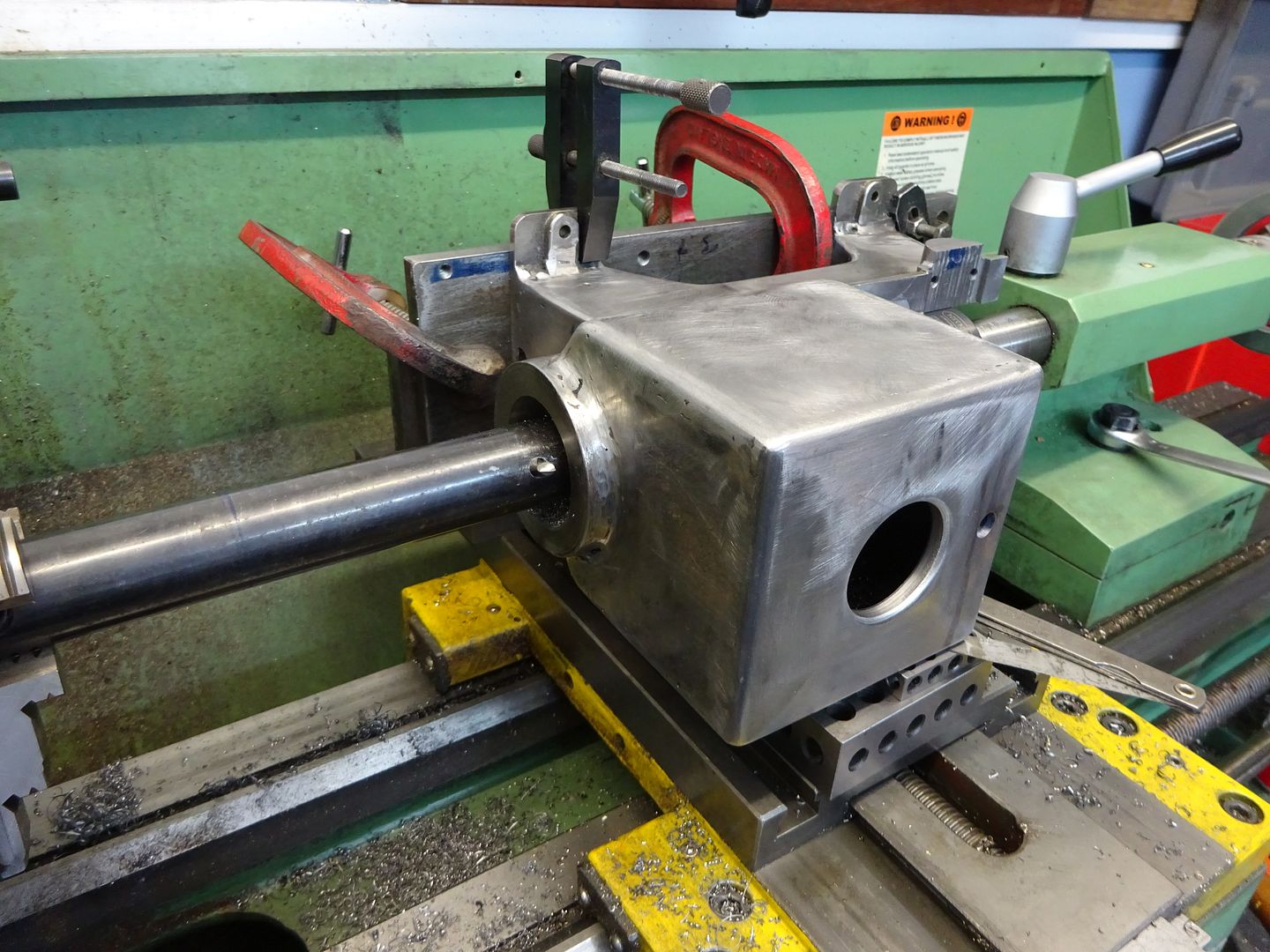
| 74 forum posts 19 photos | Jason: My rotating centre is much fatter than yours. I don't like using plain centres as they inevitably tighten up as they get warm. FF: See the photo. The 40tpi screw advances the bit by 25 thou per revolution so judging one thou is not too difficult. I'm not too bothered about the odd thou or three, I shall just make the piston and cylinder head spigot to match. |
| JasonB | 27/09/2017 18:41:30 |
25215 forum posts 3105 photos 1 articles | Never found the straight across bar to be a problem myself. Just measure the bore to see how undersize it is and you know the tool needs to be advanced half that amount where ever you measure it from within reason.
You can always tap the opposite end of the cross hole to take say a 40tpi or 0.5mm pitch screw and know that x amount of rotation of the screw will move the tool Y amount.
EDIT, Brian posted about the screw as I was typing Edited By JasonB on 27/09/2017 18:42:40 |
| Fowlers Fury | 27/09/2017 20:57:53 |
446 forum posts 88 photos | I should first confess to a late-in-life realisation that Geo.Thomas’ rather pedantic articles on model engineering were actually sound and not as doctrinaire as I had naively thought. It was whilst observing the flexing of my home-made b/bar when machining GM twin cylinders that I looked up his writing on the subject. In terms of the normal, radial b/bar he wrote “..my design attempts to provide a suitable means of advancing the cutter ended in severe weakening of the bar at the point of maximum bending-moment”. I thought that might be the explanation for my non-parallel bores and with only about 10 thou left to machine, I made his angled tool design from a wider silver steel bar which he claimed would not only flex less but also make using a micrometer for measuring tool point radius much easier. It certainly wasn't a five minute job ! I don’t decry the use of 90 deg radial tool b/bars; but merely offer that GT’s design did work much better in my particular case and has produced perfectly parallel bores without a problem many times since. |
| Thomas Gman | 22/05/2022 17:24:29 |
| 27 forum posts | Commenting to say thank you, quick web search today provided this link and set me in the right direction for a line boring operation I am about to embark on during the build of my Brooks-Stent cutter grinder. |
| duncan webster | 22/05/2022 21:04:04 |
| 5307 forum posts 83 photos | Contrary to widely held belief, silver steel is not stiffer than mild. Young modulus is a matter of chemistry, and both are very largely iron |
| Nigel Graham 2 | 22/05/2022 22:03:35 |
| 3293 forum posts 112 photos | Having made but yet to use a Hemingway Kits between-centres boring-bar set this thread is of particular interest to me. These bars have radial cutters set using a simple micrometer which also forms part of the kit. The instructions tell you to mark the head of the micrometer screw but since the graduations have no fixed reference-point with which to align, I am not sure how helpful that is. To answer Fowler's Fury point about a "smooth plug", I assume as plug-gauge. I'd pondered that and suggest not a solid plug but a ring-gauge, bored out to an easy fit on the bar. Hold this at one end of the bar using a rubber band, close-fitting O-ring or something of the sort, while actually cutting metal. |
| Martin Kyte | 22/05/2022 22:05:35 |
3445 forum posts 62 photos | I Think George's point was that the angled hole for the cutter instead of a straight one would weaken the bar less so cause less diflection and being able to get a mic between the tip of the cutter and a plain portion of the bar instead of a hole would aid in setting. George himself makes the point that silver steel is no stiffer than mild in a soft state but he does suggest it is tougher and resists abrasion better for some of the other forms of boring tool he gives designs for. regards Martin
|


Please login to post a reply.
Magazine Locator
Want the latest issue of Model Engineer or Model Engineers' Workshop? Use our magazine locator links to find your nearest stockist!
Sign up to our Newsletter
Sign up to our newsletter and get a free digital issue.
You can unsubscribe at anytime. View our privacy policy at www.mortons.co.uk/privacy
Latest Forum Posts
- *Oct 2023: FORUM MIGRATION TIMELINE*
05/10/2023 07:57:11 - Making ER11 collet chuck
05/10/2023 07:56:24 - What did you do today? 2023
05/10/2023 07:25:01 - Orrery
05/10/2023 06:00:41 - Wera hand-tools
05/10/2023 05:47:07 - New member
05/10/2023 04:40:11 - Problems with external pot on at1 vfd
05/10/2023 00:06:32 - Drain plug
04/10/2023 23:36:17 - digi phase converter for 10 machines.....
04/10/2023 23:13:48 - Winter Storage Of Locomotives
04/10/2023 21:02:11 - More Latest Posts...
- View All Topics
Support Our Partners


Shopping Partners
Subscription Offer

Latest "For Sale" Ads
- Reeves** - Rebuilt Royal Scot by Martin Evans
by John Broughton
£300.00 - BRITANNIA 5" GAUGE James Perrier
by Jon Seabright 1
£2,500.00 - Drill Grinder - for restoration
by Nigel Graham 2
£0.00 - WARCO WM18 MILLING MACHINE
by Alex Chudley
£1,200.00 - MYFORD SUPER 7 LATHE
by Alex Chudley
£2,000.00 - More "For Sale" Ads...
Latest "Wanted" Ads
- D1-3 backplate
by Michael Horley
Price Not Specified - fixed steady for a Colchester bantam mark1 800
by George Jervis
Price Not Specified - lbsc pansy
by JACK SIDEBOTHAM
Price Not Specified - Pratt Burnerd multifit chuck key.
by Tim Riome
Price Not Specified - BANDSAW BLADE WELDER
by HUGH
Price Not Specified - More "Wanted" Ads...
Get In Touch!
Do you want to contact the Model Engineer and Model Engineers' Workshop team?
You can contact us by phone, mail or email about the magazines including becoming a contributor, submitting reader's letters or making queries about articles. You can also get in touch about this website, advertising or other general issues.
Click THIS LINK for full contact details.
For subscription issues please see THIS LINK.
Digital Back Issues


Donate

 Register
 Log-in
Model Engineer Magazine
- Percival Marshall
- M.E. History
- LittleLEC
- M.E. Clock

ME Workshop
- An Adcock
- & Shipley
- Horizontal
- Mill

Subscribe Now
- Great savings
- Delivered to your door

Pre-order your copy!
- Delivered to your doorstep!
- Free UK delivery!
All Forum Topics > General Questions > Between centres boring bar bit grinding