Forum sponsored by:

ALBA 2S Shaper Refurbishment - Lots of questions!
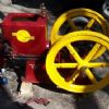
I have finally got the ALBA 2S shaper into the workshop to start Refurshing it.
| Joseph Noci 1 | 23/06/2017 15:36:09 |
| 1323 forum posts 1431 photos | I posted previously that I had found an ALBA 2S shaper in the deep South of Namibia..I did buy the shaper, and it had to do a journey of over 1200km from the Tomato farm it was located at, on the back of a Tomato shipment truck, to our Capital Windhoek. I think it was ashamed to be seen among the tomatoes, because it took a whole MONTH(!) to get from the farm to Windhoek, so I suspect it Hitch-hiked its own way.. Went to Windhoek yesterday to collect it - 380km away, and got back today.
And Yes, that's a Tomato crate... Arranged a Forklift and got it into the workshop - must be about 800kg?
It has it's vice as well. Ignore that 'tool-holder' that is a real 'Farm made' device...
Vice seems fine, except for chipped top edges where the diamond pattern of the jaw face seems to have chipped away. Why the diamond jaw face to start?? Surely that would mar the work?
The rest of the machine appears to be in very good nick indeed. Slides do not seem to show any sign of wear. The table jack-screw appears unworn, as does the table cross leadscrew. Seen below, the screws appear to be coated in a dark gunge, very thin, almost like a long-dried out grease. It chips of quite easily, and under it is a bright, shiny silver screw! You can see the three bright spots where I just removed the grunge with my finger nail. Silver underneath!
The table front support rod impinges on the base as the table moves across during cross feed, but there is NO disernable groove, marking or scratches on the base under the support rod's path at all.
Bull Gear is very clean, slightly oily, and the teeth look very good. There is no visible sign of wear along the contact area between the Rocking Bracket and the Stroke Adjusting Slide. Likewise, the gears in the gearbox are slightly oily, otherwise clean, and the teeth show no wear that I can see - teeth tips are still square edged.
The motor is a 3pahse motor, 380volt, huge, but only 1HP....1.75amps at full load, it says.. Not sure what the B.S.S - 68-1936 stands for. Some British Standard? Or is 1936 a date...? I will probably replace the motor..
These two copper pipes are obviously for lubrication, but how? With and oil can? Or where they oil-pots attached at some time? - such as in the photos 4 from the top?
I think this machine originally sat somewhere for a very long time, covered in its protection grease, doing nothing! I intend to strip the machine down completely , clean, sand down, paint, etc, Now I have to go find some Imperial spanners and Sockets.. Also wish I could find a more definitive manual on this model/type - the ones I found or have been kindly provided, all are for the Elliot/Invicta series, and they differ considerably in gearbox design and implementation, as well as a number of other key areas Joe
|
| Brian Sweeting | 23/06/2017 16:06:36 |
| 453 forum posts 1 photos | Copper tubes on motor often just had a small flap over them. Couple of drops of oil to lube the bearings. A manual is available from lathes.co.uk, link here.. https://store.lathes.co.uk/print/ma485a
BS -1936 Refers to a British Standard about screw threads. Edited By Brian Sweeting on 23/06/2017 16:13:01 Edited By Brian Sweeting on 23/06/2017 16:21:26 Edited By Brian Sweeting on 23/06/2017 16:22:14 |
| Joseph Noci 1 | 23/06/2017 20:58:47 |
| 1323 forum posts 1431 photos | Brian, thanks for the info on the manual - I do have that manual, but is is not of much use for what I need. It seems to relate mainly, even only, to the Elliot and Invicta series - certainly my ALBA 2S does not feature in some salient issues. The Gearbox of all the machines in the handbook seems to be on the side/rear, with long gear levers facing forwards. My machine's gearbox is at the rear , with a stubby gear lever to the rear. No issue in deriving how to set gears and work the machine, but I am trying to find images, pictures, etc that can help me get the machine, gearbox, bearings, etc apart. Your comment on the BS-1936...The text on the motor label is B.S.S - 68-1936 - I presume this would not have anything to do with Thread standards! Joe |
| John Olsen | 24/06/2017 04:50:59 |
| 1294 forum posts 108 photos 1 articles | Hi Joseph, That looks pretty much the same as my one, an 18 inch model. I also used to have a 14 inch one which looked much the same but had a flat belt drive and no gearbox. The 18 inch has the same gearbox as yours. The four speeds are the four detents at the top, you will soon figure out which ones are which. Yours doesn't seem to have the clutch, which mine does. The bosses on the ram just behind the head were for the optional power down feed, which mine does not have either. My lubrication points mostly have a little pot with a cap on top, with a wick to slowly feed the oil, like the ones on the drivers side of your machine. So long as you put a drop or two in each point each time you use the machine it should be fine. The vice you have is not the original, I have one that is and it does have flat jaws as well as being a bit more substantial. However, yours looks like it should be good enough for all practical purposes. I would suggest finding someone with a surface grinder and taking off the serrations from the jaws. Have you figured out the stroke adjustment yet? You loosen the knurled nut and turn the square on the shaft. (With the machine stopped!) Much nicer than other machines where you have to open the door and mess around inside. I wonder if yours was bought as surplus and then never used? The 14 inch one seemed to be like that...when I got it it was in pieces, but had the look of something that had never been used. The owner had been making a vertical mill attachment for it but never finished it. Mine has a 460 volt 3 phase motor which is already delta connected, eg I can't rewire it to a lower voltage. Nominally 3 hp. I have run it in two ways. (The sensitive should turn away about here...) One is to step up the 230 volts to 460 and apply it across two phases. This does not self start, so you turn on the power and then give the pulley a push in the required direction with a boot. This in theory should give about 2/3 of the nominal power, anyway it is plenty for all practical purposes. For instance taking a quarter of an inch cut off cast iron. The other way I have run it is with a VFD, applying the 230 Volt 3 phase from the vfd direct to the motor. This works fine, despite what the pundits may think. The motor can, in theory at least, reach half of its nominal power, eg the same current at half the voltage. This is actually plenty of power for anything I have needed to do. After all, a machine this size can remove metal faster than I can afford to buy it. Anyway...If your 1 hp motor can be rewired to delta you could use it with a vfd and run the machine off single phase. You don't say if you have 3 phase available or not. But anyway, 1 hp would be enough to do some excellent work with this machine. More might be able to remove metal faster, but then what's the hurry? regards John |
| Joseph Noci 1 | 24/06/2017 09:17:15 |
| 1323 forum posts 1431 photos | Hello John. Thank you for your informative response. I am disappointed in the non-original vice! Closer scrutiny indicates that this vice is completely fabricated - all its parts are cap-screwed together. The swivel base appears to have been machined, on a lathe, from a 200mm square by 40mm thick chunk of steel, with the semi-circular slots for the swivel bolts done on a mill. All the machining marks, very fine marks mind you, are visible. This looks like it was an Apprentice task in the time.. I also fear that this vise might be a little flimsy - I envisage some 'rocking' on its swivel base. So, now look for a vise... The seller did throw in another vice, a huge thing, very rusted and jaws more than nicked..definitely also not from this shaper.- I can just manage to lift it..
Thanks for the info on stroke adjustment - I have not got even that far I fear - I am going to strip down and clean/paint first..But that is neat! I have seen the gymnastics indicated on some other shapers to affect this adjustment!
WRT the various oilers- On the upper part of the gearbox cover at the rear are some oilers, but just seem to be holes in the casing, with a copper pipe exiting the hole and going down to the gears. Would there have been a oil-cup here? Or perhaps just one of those flip-caps that you lift and apply an oil squirt from an oil can? Hard to see if there was such a cap, as if there was, it would be broken of flush with the case.
Ditto the two pipes on the right of the gearbox case providing lube to the pulley drive shaft. No caps, or sign of cap retainer.
The Ram Gibs must have had the small flip-top oiler for oil can squirt lube method, it seems - there is only one little 'cup' left, sans lid - the lid retainer dimples can be seen on the cup though. Going to be fun trying to make oil-cups..
On the motor - I have 3phase in the shop. I also have a 2KW 3phase VFD that had no use - Wondering if this would help in 'jogging' the ram to position for stroke adjustments. Not sure yet how you set the start and end points, versus the stroke length, so not sure how the 'useful' clutch aided this, and can the VFD slow speed capability be a substitute.. How does the clutch work on these machines? I have not found any useful images or descriptions yet. I don't suppose a simple motor pivot to remove the belt tension would work well - the belt could grab in an indeterminate fashion when inching, with bum-clenching results.. Thanks John! regards joe
Edited By Joseph Noci 1 on 24/06/2017 09:20:15 |
| IanT | 24/06/2017 09:50:14 |
| 2147 forum posts 222 photos | Looks to be an interesting machine Joe - look forward to seeing how she cleans up! Regards, IanT
PS You'll need to make a 'foot' for that front table support (or maybe it should be a 'shoe' ?) |
| SillyOldDuffer | 24/06/2017 10:49:50 |
| 10668 forum posts 2415 photos | B.S.S stands for 'British Standard Specification'. The term seems to have disappeared around WW2, being replaced simply by 'BS'. Just a guess but some of the early British Standards were reports rather than full specifications; later British Standards - I think - are always specifications. 1936 is the date the specification was issued. The 68 is a mystery - it doesn't seem to have anything to do with motors. Could it be that the plate has been defaced by that rivet, and that part of the BSS number is missing? Dave |
| John Olsen | 25/06/2017 04:57:27 |
| 1294 forum posts 108 photos 1 articles | Hi Joseph, Your second vice looks more like my one, although not exactly the same. I can hardly lift mine so it sound solid enough. It looks like yours might clean up OK. The gearbox casting on mine is a bit different, the bosses for the clutch lever and rod are cast in. It has oil cups with lids on the bosses of the gear shafts on both sides. These are right on the boss, eg no copper pipe extension. This does mean that they are down behind the pulley and its guard, or would be if the guard was in place, so a bit hard to get at. It may be that yours had the same, and someone has added the pipes to make them more accessible. The clutch works from a lever on the drivers side, and stays either engaged or disengaged. Since you don't have it, you might find the inching available from a vfd useful. You set the length of the stroke as mentioned with the knurled nut and square shaft on the end of the bull gear shaft, then loosen the square on the top of the ram where the slot is, and slide the ram back and forth to adjust the position of the stroke over the job. The ram is quite heavy to pull back and forth but doable. Of course, if the nut is loose and you put the machine in gear, the nut will slide back and forth in the slot, which can let you adjust the position without manhandling the ram, but only do this on a low speed. I don't know if you will want to take the head off the ram, perhaps for painting. There is a bit of a trick to this, and having not done it for a few years I might be confusing myself with my other Alba, which is the 10 inch model. If I recall correctly, the square nut above the ram has an eccentric pin on the inside end. This engages with a segment piece which runs in a slot in the actual ram head. So to angle the head you loosen the square which unclamps the head, and it will swivel. To take it right off, you look for a small grubscrew on the side of the ram just below that square and take it out. This lets you take out the square shaft with the eccentric pin on the end, and now the head should pull out. (With the 10 inch, you have to swivel the head upside down but I don't think this is the case with the bigger one.) The trick part comes when putting it back together. The segment piece with the hole for the eccentric pin has to sit in its groove in the ram head, then you push it into place on the ram, then you drop in the shaft so that the eccentric pin engages with the hole. Except the segment piece is likely to be in the wrong place and you will spend a bit of time trying to get it all lined up! Did you get a handle with the machine? Mine came without, so I made one up by brazing a 3/4 inch drive socket onto a suitable steel flat and put a wooden handle on the other end. The one handle works for pretty well all the adjustments, including the vice. Incidently they didn't actually have a foot on the table support. Mine arrived without the whole leg, so I made up a pattern that serves for both the attachment at the top onto the table, and as a foot on the bottom. That does limit how low the table can go, so if I ever need to machine a block about 18 inches high I will have to take the foot off to let the table go lower. I don't think that is likely to be needed very often! regards John
|
| Joseph Noci 1 | 25/06/2017 15:56:52 |
| 1323 forum posts 1431 photos | Hi John, and all others! Thanks for all the info. To answer some of your questions John, I have today finished stripping down the whole machine, except for splitting the gearbox. The head is removed from the ram as well. All the slides are in good nick, with the ram slides the only ones with some rather deep scoring on the right flat base - should clen up easily enough, and then we will call them 'oil-grooves'... I do have the crank handle for the machine as well John. And you are correct, that table support is footless - the shaft end just rubs along the machine base. Maybe I will make a brass foot for it. My table cannot tilt or rotate, so the shaft end is just square. And then Lady Luck struck a really nasty blow... After removing the Ram Head, I stripped the vertical slide from the head and discovered broken dovetails, with a real kludge 'repair'...
Top of head showing crack upper right of lower dovetail.
Right side dovetail, showing added plate and screws to keep dovetail pieces in place!
Crack midway down right dovetail.
View of right dovetail 'Repair' and broken/missing piece of upper rear dovetail.
Left dovetail break.
So Sad! The rest of the machine is really in very good condition. Very little wear evident anywhere. I think the scoring on the lower flats of the Ram dovetails is due to lack of oil - the oil holes were blocked with muck and if oil was applied, it went nowhere..However, on many parts of the ram slide it appears that I can still see original machine marks, so little wear has occurred. There is no rust worth speaking of, and most of the plain metal parts are dull from oily grime - as though a greased or oily rag was used to wipe the machine down and then left for years. Going to be interesting machining a whole new one of these! There is no room to bolt on a thick plate in front and make new dovetails, nowhere to fit the fixing bolts, etc.
I have NO idea how I am going to fix this, short of make a complete new head! And bright Ideas anyone??? Joe |
| Mikelkie | 25/06/2017 18:31:06 |
 135 forum posts 13 photos |
Edited By Mikelkie on 25/06/2017 18:33:23 |
| John Olsen | 26/06/2017 00:14:23 |
| 1294 forum posts 108 photos 1 articles | That will need bit of thought. It would be easy enough if the hole for the lead screw was not there. Just machine it flat and screw on a block to machine new dovetails on. But that would leave you with about half of the hole for the lead screw. Mine had a chunk broken off the dovetail on the down slide, but that was on the side with the gibb screws, so cleaning up the break and screwing on a block was all that was needed. It is probably quite unusual to find an older machine that has not had crash at some time. On my 6 inch Ammco machine the slotted arm inside had been broken and brazed together at some point. I had a closer look at mine. It does have the two oil holes on the top of the gear box, they are a bit hidden behind the clutch actuating rod, which runs across there. No sign of oil pots and there wouldn't be room there anyway. I've taken a few photos which I will put in my album. John |
| thaiguzzi | 26/06/2017 05:44:37 |
 704 forum posts 131 photos | That dovetail damage must have been a good crash. And boy, when shapers crash, do they C R A S H... |
| Dave Martin | 27/06/2017 08:30:43 |
| 101 forum posts 11 photos | Joe, I bought a 2S several years ago but circumstances have conspired to keep me out of the workshop since then. I can't help with crack issue but in case it helps re the vice, have grabbed a few images of the vice which came with mine; it was in use with the shaper and I had been told it was original....
(just spotted un-occupied screw hole in last underneath shot!) Edited By Dave Martin on 27/06/2017 08:34:04 |
| Joseph Noci 1 | 27/06/2017 10:21:16 |
| 1323 forum posts 1431 photos | Thanks for the pics Dave. My second vice, 'given' with the shaper, seems more in line with your vice. Quite substantial and darn heavy. Why is it that the vice needs the 'through' leadscrew for shaper use? I understand the difference in terms of the one leadscrew under tension and the other in compression, by surely either would generate sufficient squeeze on the work piece? I have a big China vice, very study and well made, but with a compression leadscrew, the screw is about 25mm diameter - I doubt that would bow under the pressure? Sometimes, to the un-intiated and uneducated, a lot of this seems so much folk-lore.. Joe |
| richardandtracy | 27/06/2017 11:27:50 |
 943 forum posts 10 photos | Personally, I think you're right. 'It's always been done this way..' can sometimes morph into 'It's always been done this way because...' when someone invents a good enough story. And the stories spread because everyone likes to think things are done for a reason other than 'the designer was too lazy to think it through'. Regards, Richard.
|
| John Olsen | 29/06/2017 04:14:24 |
| 1294 forum posts 108 photos 1 articles | Well, I have never really studied the screw arrangements on the vices of my several shapers, but I would say that so long as it is a good substantial vice it will do the job. It is of course nice if it is original, especially if the machine is regarded as a kind of vintage item. They are often no longer with the machine, since a shaper vice makes a good vice for a milling machine. When I bought my 2S, the machinery dealer told me afterwards that they had regretted giving it to me for the quite cheap price, since they could have got that much for the vice alone. They probably could have to. Shaper doors are often missing too. Have you had a look at the pictures in my album yet Joseph? John |
| Joseph Noci 1 | 29/06/2017 08:38:53 |
| 1323 forum posts 1431 photos | Hi John, Yes I have looked at your photos, thanks. Your shaper is a lot bigger, for sure! I though the 2S was 'small' when I first saw it ( although I was looking for its smaller brother originally..), until I had to start lifting and manipulating it. Goodness these chunks of iron are heavy! I have a plan to fix the broken dovetails now, but that is all in the 'other' posting re what type of cast iron to use - somehow these two posts are cross pollinating too much and soon an Admin. is going to rap me knuckles.. All is stripped down to the last screw and being cleaned, all old paint removed, sanded, etc - ready to paint one of these days. Requires careful co-ordination as a fully cleaned and degreased part should really be primed the same day - in our coastal town the part will have a nice brown sheen of fine rust by the next day! I also was quite keen to replace many of the bolts an nuts with new, but nary an imperial thread to be found in Southern Africa.. I have taken many photos during the strip down so that I can see which parts goes where and how..I will post some photos as the work proceeds - at least when I am tired of cleaning and sanding, and sufficiently high on thinners, and can digress and start making my dovetail cutter... Right, lets go sniff some more thinners...
Joe |
| Joseph Noci 1 | 12/07/2017 12:38:59 |
| 1323 forum posts 1431 photos | There is progress on the ALBA 2S cleanup, a bit slow as it is cold in the shop at the moment. Also, humidity is so high that rust is a menace right now! Some pics of the cleanup are shown, but in the process I found that the Ram slides have some deep scoring. The right hand horizontal slide on the column and the Ram ( Ram underside) show deep scoring from the middle of the slide almost all the way to the rear of the slide. The forward half is good, small scoring, and the left slide is pretty good as well, with a small scored section. Some photos are below. Do I need to concern myself about this? I suppose I do, but how badly? Is there anything I can do to remedy this to some useful extent? Applying fine brass dust filled epoxy and sanding smooth? Maybe that will make matters worse if the epoxy comes loose.. The worst of the scoring is almost across the width of the slide face, and score depth varies from a thumbnail detectable nick, to maybe 0.2 to 0.4mm deep. There is not a mill or shaper within 1500km from me where the surfaces could maybe be re-finished.. The column left side flat slide, showing good surface
The worst part of the right side column flat slide.
Ram flat slide, right side under - a bad area.
Another bad section of the Ram rights underside flat slide.
The cleanup in progress:
Bull Gear
Column is done, the base next
Joe |
| IanT | 12/07/2017 14:18:00 |
| 2147 forum posts 222 photos | With regard shaper vices, I've always assumed that they are 'pull' close (rather than 'push' ) because of the side forces involved in shaper work. If the jaws are set parallel to the ram movement, then there is no difference that I can think of. But if the vice is rotated 90 degrees to the ram direction, then the ram 'impact' will normally be against the moving jaw (as the clamping handle will be away from the shaper body) and I think that a moving jaw held by a screw passing right through its body has to be a bit more robust than a moving jaw being simply pushed closed from the rear (as many milling or drilling vices are). As I've said - that's what I've always "assumed" and not being any sort of trained engineer (and certainly no rocket scientist) this may be completely false - but as a regular shaper 'user' it seems to make good sense to me. I think the same argument holds when you think about why shaper vices are quite shallow (compared to other vices). Most milling processes don't generate anything like the side forces that a shaper can do. Anyway - that's my theory and I'm sticking with it! Regards,
IanT
Edited By IanT on 12/07/2017 14:19:26 |
| Joseph Noci 1 | 23/07/2017 23:04:27 |
| 1323 forum posts 1431 photos | Well, there is progress in the refurbishment! It has been messy, and the winter here has not helped the mindset.. Anyway, focus has been on cleaning every bit up, sanding, derusting, sanding some more, and painting has started - most of the small bits are painted and done. I am going to commit a sacrilegious act however - I intend to leave of all those clickety-clack levers, gears and widgets that do table horizontal feed, and fit stepper motors to the horizontal feed and the vertical feed slide ( When I repair the dovetails of course...!) Not going to make a CNC shaper...just electronic feed for the two modes, with no automated syncing of the two to cut profiles etc. Horizontal feed will still take place at the ram rear position as normal.. I made a trolley for the machine to stand on - 60x60x10mm angle iron, with 180mm wheels at the rear, and a single steering wheel in front, to maneuver the shaper into position more easily. Big jack-screws at the shaper bolt-down holes then lift the shaper trolley off the wheels, the wheels then removed and the jackscrews screwed released dropping the frame down onto heavy jack plates with rubber between them and the floor. The jackscrews can be adjusted to level the shaper. Some pics of progress so far: The trolly:
Trolley front jackscrews in place
Shaper base on trolley
Front Jackscrews screwed in to raise trolley to remove front wheels.
one of the jackplates - 8mm steel plate with a countersink for the jackscrew tip. 12mm rubber belting under the plate. Plate is 150mm square
Column interior painted and fitted to base - mounted on trolley to move into paint shop.
Most of the other parts are painted.
And the other parts all cleaned up and shiny..
The Rusty vice stripped down
And into the electrolytic de-rusting bath..
All nice and clean now..
Painting continues - hopefully I can assemble most bits by next weekend! And some work has started on the broken dovetail - The 'old' dovetail has been sawn off, and a slice of phosphor bronze obtained to cut a new dovetail and bolt the new section onto the front of the skimmed clean ram head.
Joe...
|


Please login to post a reply.
Magazine Locator
Want the latest issue of Model Engineer or Model Engineers' Workshop? Use our magazine locator links to find your nearest stockist!
Sign up to our Newsletter
Sign up to our newsletter and get a free digital issue.
You can unsubscribe at anytime. View our privacy policy at www.mortons.co.uk/privacy
Latest Forum Posts
- *Oct 2023: FORUM MIGRATION TIMELINE*
05/10/2023 07:57:11 - Making ER11 collet chuck
05/10/2023 07:56:24 - What did you do today? 2023
05/10/2023 07:25:01 - Orrery
05/10/2023 06:00:41 - Wera hand-tools
05/10/2023 05:47:07 - New member
05/10/2023 04:40:11 - Problems with external pot on at1 vfd
05/10/2023 00:06:32 - Drain plug
04/10/2023 23:36:17 - digi phase converter for 10 machines.....
04/10/2023 23:13:48 - Winter Storage Of Locomotives
04/10/2023 21:02:11 - More Latest Posts...
- View All Topics
Support Our Partners


Shopping Partners
Subscription Offer

Latest "For Sale" Ads
- Reeves** - Rebuilt Royal Scot by Martin Evans
by John Broughton
£300.00 - BRITANNIA 5" GAUGE James Perrier
by Jon Seabright 1
£2,500.00 - Drill Grinder - for restoration
by Nigel Graham 2
£0.00 - WARCO WM18 MILLING MACHINE
by Alex Chudley
£1,200.00 - MYFORD SUPER 7 LATHE
by Alex Chudley
£2,000.00 - More "For Sale" Ads...
Latest "Wanted" Ads
- D1-3 backplate
by Michael Horley
Price Not Specified - fixed steady for a Colchester bantam mark1 800
by George Jervis
Price Not Specified - lbsc pansy
by JACK SIDEBOTHAM
Price Not Specified - Pratt Burnerd multifit chuck key.
by Tim Riome
Price Not Specified - BANDSAW BLADE WELDER
by HUGH
Price Not Specified - More "Wanted" Ads...
Get In Touch!
Do you want to contact the Model Engineer and Model Engineers' Workshop team?
You can contact us by phone, mail or email about the magazines including becoming a contributor, submitting reader's letters or making queries about articles. You can also get in touch about this website, advertising or other general issues.
Click THIS LINK for full contact details.
For subscription issues please see THIS LINK.
Digital Back Issues


Donate

 Register
 Log-in
Model Engineer Magazine
- Percival Marshall
- M.E. History
- LittleLEC
- M.E. Clock

ME Workshop
- An Adcock
- & Shipley
- Horizontal
- Mill

Subscribe Now
- Great savings
- Delivered to your door

Pre-order your copy!
- Delivered to your doorstep!
- Free UK delivery!
All Forum Topics > Manual machine tools > ALBA 2S Shaper Refurbishment - Lots of questions!