Forum sponsored by:

Oscillating Engine Valve Gear Query
| JasonB | 31/07/2016 19:49:05 |
 25215 forum posts 3105 photos 1 articles | I have come across an old etching of an oscillating engine that looks like it would be a nice project to make.
You can hopefully see in the above that it has a slide valve that is opperated by a rocker arm pivoted off the side of the cylinder with the other end running in a grooved "channel" that I believe can be moved to reverse the engine. Before I spend some time trying to work out the exact geometry of the linkages I was woondering if anyone had a drawing of this type of valve gear in an old book of knew of an engine fitted with it. Unlike a lot of oscillating engines this one does not have an eccentric to move the valve like you find on say Penn's valve gear. Thanks, Jason |
| Peter Krogh | 31/07/2016 20:44:30 |
 228 forum posts 20 photos | That looks very like a Hackworth type set-up. The roller in the end of the valve lever would engage the channel located above the bearing/trunion. It would make a great model!! Pete
|
| JasonB | 01/08/2016 14:53:13 |
25215 forum posts 3105 photos 1 articles | Thanks Peter. The Hackworth gear does indeed look like it has a similar channel which lets the valve lead the crank depending on what angle the channel is at. Just need to work out the geometry that will move the valve rod in using the cylinders movement rather than the link from the crank that the Hackworth uses. I too think it sould make a nice model, The old advert says the engine came in 4", 6" and 8" bores, it does not help that the bricks on the wall vary in length but I think I will assume that the 6" is illustrated so at 1/4 scale that would give me a 1.5" bore x 3" stroke which my compressor can just about keep up with. The flywheel will also be an easy job cut from the solid. Watch this space J
PS While I'm here I seem to remember the SMEE having an old oscillating wall engine that they have on their stand at some shows, does anyone have a photo of it?
Edited By JasonB on 01/08/2016 14:54:59 |
| JasonB | 01/08/2016 15:21:52 |
25215 forum posts 3105 photos 1 articles | Looks like Elmers No 42 may hold the missing link Edited By JasonB on 01/08/2016 15:22:04 |
| Peter Krogh | 01/08/2016 16:22:25 |
228 forum posts 20 photos | I'm a bit confused by the illustration as it shows the 'roller' not engaged in the 'slot'. I don't see any mechanism for moving the 'slot' over to the 'roller' either. ?????? Pete
|
| JasonB | 01/08/2016 18:27:01 |
25215 forum posts 3105 photos 1 articles | I think what you are saying is the roller is actually the nut holding the rocker arm onto the cylinder, the arm carries on towards the wall which would place the roller towards the rear of the slot. I can't blow the image up much more without it pixellating.
Edited By JasonB on 01/08/2016 18:34:24 |
| Neil Wyatt | 01/08/2016 19:11:47 |
 19226 forum posts 749 photos 86 articles | If you can figure out taht one, you should draw up plans and send it to Diane! The Flywheel will suit fabrication, I like the balancing pockets! Some interesting challenges in making the 'forged' crankshaft and in making steam-tight pivots, but the steam passages should all be possible to do as straight lines. Neil |
| Peter Krogh | 01/08/2016 19:40:09 |
228 forum posts 20 photos | Jason, Got it! I couldn't get an enlargement like you have. I agree with your assessment, especially since it puts the roller back in line with the trunions on the cylinder. That bothered me also. I'm adding this engine to my build list (which is too long!). While castings would be really nice, bar stock will do a good job also. Neil, I'm pretty sure how i would do the crank. A bit fiddly but..... Fascinating engine!! Pete |
| JasonB | 01/08/2016 20:04:39 |
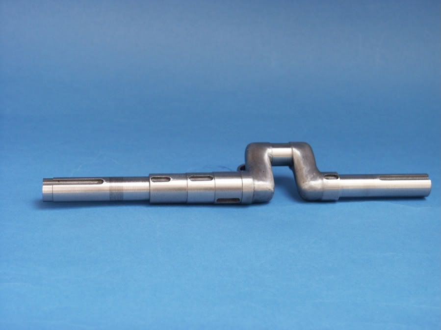
25215 forum posts 3105 photos 1 articles | You could go teh forging and bending from solid route but it would need a good heat source to form tight bends. Or the other opttion is to just machine it as you would a solid crank and rather than leave the webs rectangular section shape then so the are round, this could be done with a roundover bit followed by files. A third option would be that I design it to use a SG iron cast crank from something else like this one one of mine.
|
| duncan webster | 01/08/2016 23:07:37 |
| 5307 forum posts 83 photos | I suspect there is something missing from the engraving. If the curved slide thing was mounted in slides so that an eccentric on the crankshaft caused it to move up and down vertically, then it would operate the valve, and compensate for the waggling of the cylinder. Not perfectly, but on a simple thing like this you'd get away with it |
| JasonB | 02/08/2016 07:32:34 |
25215 forum posts 3105 photos 1 articles | Duncan, there are several designs that use an eccentric such as Penn's which I mentioned earlier. But this one does not use an eccentric there are a few ways these were arranged, in this case there is a STRAIGHT channel much like on Joy or Hackworth valve gear but the rocking motion of the valve chest provides the main source of movement not an eccentric. The only thing I can't see is an actual reversing lever for the operator to select direction. This is one example without an eccentric but as the pivot is fixed off to one side of the pivot point the engine can't be reversed, also better suited to end pivoting rather than middle. Valve gear closeup at about 1min in. And this is Elmers No 42 which is close to whats needed but not reversible
Edited By JasonB on 02/08/2016 07:44:09 |
| Neil Wyatt | 02/08/2016 08:25:26 |
19226 forum posts 749 photos 86 articles | > The only thing I can't see is an actual reversing lever for the operator to select direction. It may be for driving line shafting, perhaps you just angle the channel to give the direction you want, bolt it up and leave it. Neil |
| Gwil | 03/08/2016 14:39:07 |
| 14 forum posts 5 photos | As requested, some pics of the SMEE model wall engine:
|
| JasonB | 03/08/2016 14:51:08 |
25215 forum posts 3105 photos 1 articles | Thank you very much Gwil. It is even closer to the engraving than I remembered. Almost certainly based on the same engraving as that is dated 1876, the same as the lable on the model. I have also been given a lead that Anthony Mount mad something similar but as it was not a good runner he only wrote a single article so I'll be searching for that later. Edited By JasonB on 03/08/2016 14:53:39 |
| Peter Krogh | 03/08/2016 16:04:47 |
228 forum posts 20 photos | Posted by Neil Wyatt on 02/08/2016 08:25:26:
> The only thing I can't see is an actual reversing lever for the operator to select direction. It may be for driving line shafting, perhaps you just angle the channel to give the direction you want, bolt it up and leave it. Neil I suspect that this is how it was done. Adding a lever would be easy though. Pete |
| Peter Krogh | 03/08/2016 16:09:06 |
228 forum posts 20 photos | That's a beautiful model and it looks to have been run a fair bit. Nice. Pete
|
| duncan webster | 03/08/2016 16:46:40 |
| 5307 forum posts 83 photos | If the only thing that moved the valve is a roller travelling in a curved slot, then the valve motion will be 90 degrees out of phase with the piston motion, so it will work with zero lap and 100% admission. If lap is applied the valve won't open until after top centre, which would make it more than a bit sluggish. |
| Gwil | 03/08/2016 17:08:39 |
| 14 forum posts 5 photos | Rummaging about in my computer I found another shot I'd taken (not that it adds a great deal, but here it is anyway) -
Edited By Gwil on 03/08/2016 17:09:17 |
| JasonB | 03/08/2016 18:58:17 |
25215 forum posts 3105 photos 1 articles | Posted by duncan webster on 03/08/2016 16:46:40:
If the only thing that moved the valve is a roller travelling in a curved slot, then the valve motion will be 90 degrees out of phase with the piston motion, so it will work with zero lap and 100% admission. If lap is applied the valve won't open until after top centre, which would make it more than a bit sluggish. As I said earlier the roller is in a straight slot that is set at an angle. By altering the angle of the slot you can set the valve to lead the crank in either direction and therefore reverse the engine, the steeper the slot the more lead the valve has. Have a look on you-tube for some examples of hackworth or Joy valve gear to see how the straight slot works. The only difgference here is how the movement is generated. From having seen that SMEE one running at the shows I would say it's a good runner. J
PS Thanks for the extra photo Gwil. |
| duncan webster | 03/08/2016 23:09:51 |
| 5307 forum posts 83 photos | Posted by JasonB on 03/08/2016 18:58:17:
Posted by duncan webster on 03/08/2016 16:46:40:
If the only thing that moved the valve is a roller travelling in a curved slot, then the valve motion will be 90 degrees out of phase with the piston motion, so it will work with zero lap and 100% admission. If lap is applied the valve won't open until after top centre, which would make it more than a bit sluggish. As I said earlier the roller is in a straight slot that is set at an angle. By altering the angle of the slot you can set the valve to lead the crank in either direction and therefore reverse the engine, the steeper the slot the more lead the valve has. Have a look on you-tube for some examples of hackworth or Joy valve gear to see how the straight slot works. The only difgference here is how the movement is generated. From having seen that SMEE one running at the shows I would say it's a good runner. J
PS Thanks for the extra photo Gwil. Should have spotted straight slide, but no matter what angle the slide is set to the valve is at its mid travel when the cylinder is vertical (it must be for symmetry), and at its max travel when the cylinder is at max inclination (approx half stroke) so altering the angle only changes the magnitude of the valve travel, not the angle of advance. This is not the same as Hackworth/Joy which add a variable out phase component to a fixed amplitude in phase component to achieve variable angle of advance. Yes setting the slide the opposite slope will reverse the engine. Edited By duncan webster on 03/08/2016 23:16:02 Edited By duncan webster on 03/08/2016 23:16:58 |


Please login to post a reply.
Magazine Locator
Want the latest issue of Model Engineer or Model Engineers' Workshop? Use our magazine locator links to find your nearest stockist!
Sign up to our Newsletter
Sign up to our newsletter and get a free digital issue.
You can unsubscribe at anytime. View our privacy policy at www.mortons.co.uk/privacy
Latest Forum Posts
- hemingway ball turner
04/07/2025 14:40:26 - *Oct 2023: FORUM MIGRATION TIMELINE*
05/10/2023 07:57:11 - Making ER11 collet chuck
05/10/2023 07:56:24 - What did you do today? 2023
05/10/2023 07:25:01 - Orrery
05/10/2023 06:00:41 - Wera hand-tools
05/10/2023 05:47:07 - New member
05/10/2023 04:40:11 - Problems with external pot on at1 vfd
05/10/2023 00:06:32 - Drain plug
04/10/2023 23:36:17 - digi phase converter for 10 machines.....
04/10/2023 23:13:48 - More Latest Posts...
- View All Topics
Support Our Partners


Shopping Partners
Subscription Offer

Latest "For Sale" Ads
- Reeves** - Rebuilt Royal Scot by Martin Evans
by John Broughton
£300.00 - BRITANNIA 5" GAUGE James Perrier
by Jon Seabright 1
£2,500.00 - Drill Grinder - for restoration
by Nigel Graham 2
£0.00 - WARCO WM18 MILLING MACHINE
by Alex Chudley
£1,200.00 - MYFORD SUPER 7 LATHE
by Alex Chudley
£2,000.00 - More "For Sale" Ads...
Latest "Wanted" Ads
- D1-3 backplate
by Michael Horley
Price Not Specified - fixed steady for a Colchester bantam mark1 800
by George Jervis
Price Not Specified - lbsc pansy
by JACK SIDEBOTHAM
Price Not Specified - Pratt Burnerd multifit chuck key.
by Tim Riome
Price Not Specified - BANDSAW BLADE WELDER
by HUGH
Price Not Specified - More "Wanted" Ads...
Get In Touch!
Do you want to contact the Model Engineer and Model Engineers' Workshop team?
You can contact us by phone, mail or email about the magazines including becoming a contributor, submitting reader's letters or making queries about articles. You can also get in touch about this website, advertising or other general issues.
Click THIS LINK for full contact details.
For subscription issues please see THIS LINK.
Digital Back Issues


Donate

 Register
 Log-in
Model Engineer Magazine
- Percival Marshall
- M.E. History
- LittleLEC
- M.E. Clock

ME Workshop
- An Adcock
- & Shipley
- Horizontal
- Mill

Subscribe Now
- Great savings
- Delivered to your door

Pre-order your copy!
- Delivered to your doorstep!
- Free UK delivery!
All Forum Topics > Stationary engines > Oscillating Engine Valve Gear Query