Forum sponsored by:

Micrometer Boring Head in MEW 239 Query
| Jon Gibbs | 17/05/2016 08:41:58 |
| 750 forum posts | I've just got round to making this based upon the free plan and having made almost all of the parts I'm struggling to know where to position the threaded hole for the leadscrew nut in the boring head body? There are no dimensions on the drawing to indicate its position. Thinking about it, it looks as if clockwise rotation of the RH threaded leadscrew should advance the cut which would ideally have the nut on the far-side of centre to give maximum slide travel but the diagrams appear to show it on the closer side of centre which has me confused further. Any guidance would be gratefully received. Many thanks Jon
|
| Jon Gibbs | 19/05/2016 08:50:09 |
| 750 forum posts | Ok, so I suppose that no one else has made one yet? I decided to go back to first principles and check the operation and position of the boring bar holes and indeed I'm now convinced that the M5 threaded hole for the leadscrew nut should be on the far-side of centre at about 30mm from the face where the leadscrew dial fits. From my reading, the drawings are in conflict with that. The exploded view of the head in Fig. 1 shows the hole on the nearer-side (lower in this case) and Fig. 3 seems to show both the dovetails and the threaded hole to accept the arbor in solid lines rather than dotted as if they were on the front face. The side view shows the M5 set-screw holes in a consistent manner with Fig 1. I now think that this is wrong. I've now finished the main boring head and although I haven't yet bored the holes to accept the boring bars, the leadscrew and dovetails do work well and seem to give the correct range of adjustment. I hope this proves useful to someone. Jon |
| Mick Henshall | 19/05/2016 10:24:28 |
 562 forum posts 34 photos | I'm afraid I can't help but am sure our more learned brethren will help in due course, hope it works out ok Jon Mick |
| Bernard Wright | 19/05/2016 10:36:54 |
 90 forum posts 16 photos | Jon, Any chance of some pictures, it's good to see other's projects... Bernard. |
| Jon Gibbs | 19/05/2016 11:19:22 |
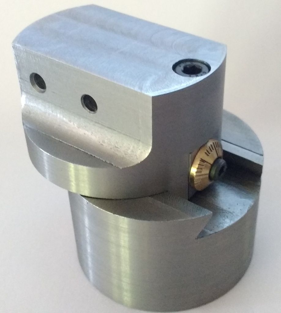
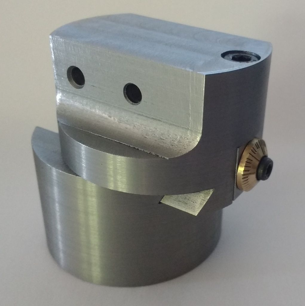
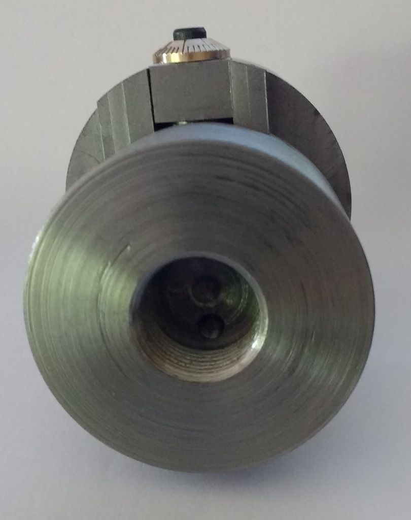
| 750 forum posts | Hi Bernard, Glad to oblige. First image is the head at full extent (maximum radius for outer boring bar). The second and third images are wound right out showing clearance to insert the leadscrew support and the position of the leadscrew nut underneath.
It's not perfect although the pictures are a bit unforgiving at this scale IMHO. There was some backlash in the indexing during marking of the brass scale wheel which I didn't account for well. The only ball end mill I had was quite blunt giving a rougher finish than I'd have liked and there seems to be some misalignment between the flat and the radiussed portion on the sides. As you can see I still need to bore the housings for the boring bars on the lathe - not sure whether to use 3/8" or 10mm. I then need to tap the set screw holes for the retaining screws. Otherwise it's done. I have made two arbors - a 2MT and an R8 for the lathe and mill respectively. Jon Edited By Jon Gibbs on 19/05/2016 11:20:34 Edited By Jon Gibbs on 19/05/2016 11:21:39 |
| Neil Wyatt | 19/05/2016 16:06:26 |
 19226 forum posts 749 photos 86 articles | I'd better respond! The position of the threaded hole is closer to the dial assembly as is clear from the exploded diagram. This makes assembly easier. The views of the body are 'upside down' compared to the exploded view. As Jon's images show this give plenty of usable travel - I don't think it would be wise to wind the upper part out further than his pictures show. Nice to see pictures of things made to plans in the magazine. Any other examples (not just boring heads). Here's the original doing a job of work:
Neil |
| JasonB | 19/05/2016 16:13:44 |
 25215 forum posts 3105 photos 1 articles | I'd say the M5 tapped hole if 5mm off the ctr line of the head as it falls between two of the gib adjusting screws which are on 10mm ctrs
Edited By JasonB on 19/05/2016 16:15:42 |
| Jon Gibbs | 19/05/2016 16:32:51 |
| 750 forum posts | Posted by Neil Wyatt on 19/05/2016 16:06:26:
The position of the threaded hole is closer to the dial assembly as is clear from the exploded diagram. This makes assembly easier. The views of the body are 'upside down' compared to the exploded view. As Jon's images show this give plenty of usable travel - I don't think it would be wise to wind the upper part out further than his pictures show. Neil, Thanks very much for the response. I guess we're only talking about 10mm between the two positions (5 mm either side of centre as Jason says) and the following comments are with due deference to the designer of course 1) On my version, at least, the assembly limiting factor seems to be the leadscrew length since that has to be withdrawn fully out of the way to allow the leadscrew support to be inserted into the 7mm hole in the slide without interference. I can see that it'd be easier though with more than a fraction of a mm of clearance. 2) I positioned the leadscrew nut on the far-side of centre to give a combination of enough clearance to insert the leadscrew support but to also provide maximum travel because I think that occurs when the leadscrew nut is hard up against the leadscrew support? I guess that there is perhaps more leeway to its position at the end of the day than I thought but perhaps there is also a bit more travel than originally planned as well?. Jon |
| I.M. OUTAHERE | 19/05/2016 16:38:58 |
| 1468 forum posts 3 photos | Looking at fig 3 the holes for the boring bar lock screws are at 10mm centres and the drawing shows the centre line of the hole for the leadscrew nut runs halfway between the centre boring bar screw hole and the outer one so 5mm off centre and on the opposite side to the lead screw dial . This would give 12mm travel when turning the leadscrew clockwise from the point where the head and slide align , you would have around 3.5 mm of the end of the leadscrew protruding from the leadscrew nut at this point and this gives you some movement to turn the leadscrew counterclockwise from the point where the head and slide align . This can be usefull for tool overlap when using the boring head to open up holes that start out fairly small and you have to change the position of the boring barfrom the middle hole to the outer hole to achieve the larger hole sizes as needed - but as with all things it comes at the cost of losing some boring diameter which can be worked around using a different way of mounting the boring bar in the boring head Neil, how is assembly made easier having the leadscrew nut on the same side as the dial ? As the retaining screw for the leadscrew support is on the same side as the dial negating the ability to mount a boring bar on that side and having the leadscrew nut closest to the dial gives a minimal amount of travel from the point where the body and slide align when turning the leadscrew clockwise . I believe having the leadscrew nut on the same side as the dial means the centre boring bar hole starts out on centre (body & slide aligned )and its swing increases as you turn the dial counterclockwise but this means the outer boring bar hole has its swing reduced as it is move towards the centre ? Edited By XD 351 on 19/05/2016 17:20:04 |
| Neil Wyatt | 19/05/2016 17:55:31 |
19226 forum posts 749 photos 86 articles | Posted by XD 351 on 19/05/2016 16:38:58:
Neil, how is assembly made easier having the leadscrew nut on the same side as the dial ?
I THINK that if the leadscrew is assembled to the leadscrew support, you can just about wangle it in with the nut in that position, allowing dis-assembly. My recollection may be wrong, though. Neil |
| Bernard Wright | 19/05/2016 18:50:39 |
90 forum posts 16 photos | Hi Jon, The pics are impressive, after all we are hobby machinists, and you've created something you can use, and be pleased that any jobs you do with it, you can say to yourself 'I did that'. I've learnt the hard way striving for absolute perfection is an endless and costly goal, I've spent thousands, and still can't achieve what others seem to do with ease. Go for what's good for you, don't be too critical of your own work, doing something worthwhile is all that matters... I believe the 10mm tools would be more abundant for say Tungsten tipped types, the 3/8" ones more for HSS..I may be wrong... Bernard. |
| I.M. OUTAHERE | 19/05/2016 19:18:53 |
| 1468 forum posts 3 photos | An adjustment of my previous post is needed ! The locking screws at 10mm centres are for the gib strip not the boring bar and the inner boring bar hole is not on centre but off set 2.5 mm towards the dial end of the slide , sorry i was flipping back and forth between this forum and pocket mags to check the drawings! Neil , i would have though assembly to be the opposite to dissassembly - well that is what my Gregorys' car repair manual would leave one to believe ! I thought that the assembly of these components would be very similar to that of the lathe cross or compound slide on a sieg C2 lathe , slide the dovetails in until the nut hits the end of the feedscrew then turn the feedscrew counterclockwise until you feel the threads click and then wind the feedscrew into the nut - if that doesn't work pound it into submission with the biggest hitting implement you can find ! Ian |
| Neil Wyatt | 21/05/2016 08:47:05 |
19226 forum posts 749 photos 86 articles | Ian, That would work - if you made the slot for the feedscrew the full length of the slide, rather than a pocket. As it is you have to fit the slide form the far side then wangle the support & leadscrew in in OR fit leadscrew then slide then support then screw the dial on to the end of the feedscrew. On reflection taking the slot right across might have been better, but it wouldn't look as good. |
| I.M. OUTAHERE | 23/05/2016 20:18:12 |
| 1468 forum posts 3 photos |
Neil, now i see what you mean ! Having the slot open would allow swart and dirt to get into the area that is supposed to ptotect the leadscrew thread also . If i'm getting this right the outer boring bar mounting hole( furthest from the dial ) will give you the maximum bore diameter with this boring head when the slide fully engaged in the dovetail ? Ian. |
| Neil Wyatt | 23/05/2016 21:03:48 |
19226 forum posts 749 photos 86 articles | You can move either side of centre. Lets call 'in' when the dial is screwed clockwise and out when it is screwed anticlockwise. A small movement in allows the middle boring bar to move to being central, smallest setting. When wound right out the central hole will bore bigger diameter than the outer hole, so their ranges overlap - this is intentional. Wound right in the outer hole is beyond the edge of the boring bar body allowing holes over 2" diameter to be bored. Essentially it is set up so that despite limited movement you can still work from the size of your smallest boring bar up to 2"/50mm. Bear in mind that the practical limit depends on how firmly the slide is supported when wound out, so extended movement is not really wanted. You can always add a horizontal boring bar hole for really big diameters. With a stubby bar just protruding you could get down to just over 50mm, and maximum diameter depends on what sort of overhang you dare risk! Neil |
| I.M. OUTAHERE | 23/05/2016 21:10:27 |
| 1468 forum posts 3 photos | Some quick sums seems to indicate that by using the boring bar hole that is closest to the dial will bore a larger hole by 3mm dia if you wind the leadscrew out until it is just full engaged in the leadscew nut . My thinking was that if the outer hole(furthest from dial ) could bore the larger diameter with the dovetails fully engaged it is a stronger set up than having the slide half way out on the dovetail . Ian. |


Please login to post a reply.
Magazine Locator
Want the latest issue of Model Engineer or Model Engineers' Workshop? Use our magazine locator links to find your nearest stockist!
Sign up to our Newsletter
Sign up to our newsletter and get a free digital issue.
You can unsubscribe at anytime. View our privacy policy at www.mortons.co.uk/privacy
Latest Forum Posts
- hemingway ball turner
04/07/2025 14:40:26 - *Oct 2023: FORUM MIGRATION TIMELINE*
05/10/2023 07:57:11 - Making ER11 collet chuck
05/10/2023 07:56:24 - What did you do today? 2023
05/10/2023 07:25:01 - Orrery
05/10/2023 06:00:41 - Wera hand-tools
05/10/2023 05:47:07 - New member
05/10/2023 04:40:11 - Problems with external pot on at1 vfd
05/10/2023 00:06:32 - Drain plug
04/10/2023 23:36:17 - digi phase converter for 10 machines.....
04/10/2023 23:13:48 - More Latest Posts...
- View All Topics
Support Our Partners


Shopping Partners
Subscription Offer

Latest "For Sale" Ads
- Reeves** - Rebuilt Royal Scot by Martin Evans
by John Broughton
£300.00 - BRITANNIA 5" GAUGE James Perrier
by Jon Seabright 1
£2,500.00 - Drill Grinder - for restoration
by Nigel Graham 2
£0.00 - WARCO WM18 MILLING MACHINE
by Alex Chudley
£1,200.00 - MYFORD SUPER 7 LATHE
by Alex Chudley
£2,000.00 - More "For Sale" Ads...
Latest "Wanted" Ads
- D1-3 backplate
by Michael Horley
Price Not Specified - fixed steady for a Colchester bantam mark1 800
by George Jervis
Price Not Specified - lbsc pansy
by JACK SIDEBOTHAM
Price Not Specified - Pratt Burnerd multifit chuck key.
by Tim Riome
Price Not Specified - BANDSAW BLADE WELDER
by HUGH
Price Not Specified - More "Wanted" Ads...
Get In Touch!
Do you want to contact the Model Engineer and Model Engineers' Workshop team?
You can contact us by phone, mail or email about the magazines including becoming a contributor, submitting reader's letters or making queries about articles. You can also get in touch about this website, advertising or other general issues.
Click THIS LINK for full contact details.
For subscription issues please see THIS LINK.
Digital Back Issues


Donate

 Register
 Log-in
Model Engineer Magazine
- Percival Marshall
- M.E. History
- LittleLEC
- M.E. Clock

ME Workshop
- An Adcock
- & Shipley
- Horizontal
- Mill

Subscribe Now
- Great savings
- Delivered to your door

Pre-order your copy!
- Delivered to your doorstep!
- Free UK delivery!
All Forum Topics > Model Engineers' Workshop. > Micrometer Boring Head in MEW 239 Query