Forum sponsored by:

Rodney Milling Aattachment
Stiff Quill?
| jonathan olley | 19/02/2016 21:35:32 |
| 21 forum posts 13 photos | Many years ago I bought a Rodney Milling attachment. Although the quill was stiff to turn overall the unit looked in good condition. Ten years later.....I decide to get it running and presume that it just needs some tlc and oil. As I have stripped the unit down, there not being very much of it i have discovered that there is more too the problem and my early hubris seems to have bitten me fair and square. The quill will turn but not freely. It is stiff, binding even and I can find no obvious way to dismantle it further for an inspection/removal of the ball-races. I wonder if there is anyone out there who might be able to shed some light on this problem. I should also point out that I don't believe the problem to be one of 'lack of lubrication'. I've had a go with various oils and nothing seems to improve. It feels like over-tight bearings...lumpy. Though the upper races seem in tip-top condition as does the unit as a whole? I'm a complete novice but I am technically and practically minded. Any input gratefully received. Cheers, j.o.
|
| Ady1 | 20/02/2016 10:52:53 |
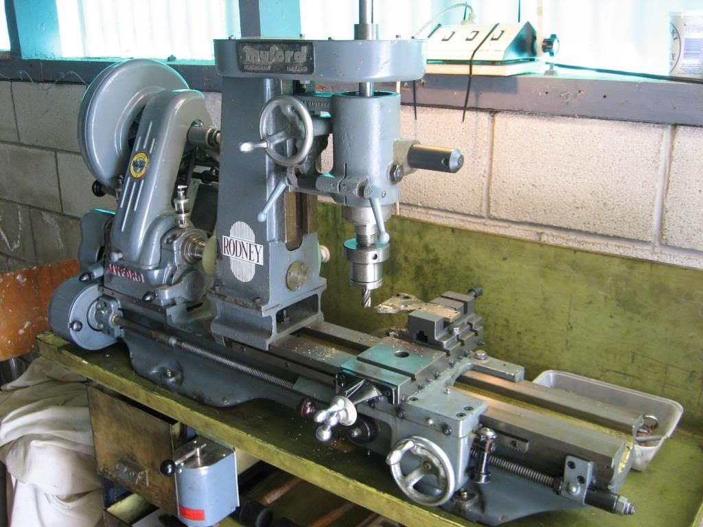
 6137 forum posts 893 photos | Pulled from t'internet
|
| Ady1 | 20/02/2016 10:57:39 |
6137 forum posts 893 photos | Looks a bit weedy at the lathe bed end to me... The most horrible thought I had was a warped spindle, I know precisely zero about these units though A few threads here
Edited By Ady1 on 20/02/2016 11:01:40 |
| John Haine | 20/02/2016 15:03:46 |
| 5563 forum posts 322 photos | If it's been standing unused fpor 10+ years, the lube in the lower bearing may well have solidified. I had the same problem on an old Quorn, where I had to dismantle the spindle and thoroughly clean the bearings with white spirit. More photos of the spindle assembly, especially at the top where there should be some form of nut (possibly castellated, maybe split with a locking screw) to apply axial loading to the bearings, would be helpful. You can get instructions/spec from: **LINK**
|
| jonathan olley | 20/02/2016 18:06:18 |
| 21 forum posts 13 photos | Hi, thank you for the replies. Firstly I hope the shaft is not warped but I understand this could be a possibility but a bit like when the car wont start i check to see if it's got fuel before I tackle the hydraulic injectors! I can see that the lower ball race could be clagged-in but until I can dismantle the quill completely i cannot tell the state of the lower races or if the shaft is warped or not and I cannot for the life of me work out how this is to be done!! Is it possible that this is a 'fit-and-forget' assembly....? And thanks for all the links btw. Cheer, j.o. |
| jonathan olley | 20/02/2016 18:18:37 |
| 21 forum posts 13 photos | p.s. here are some photos showing how far I've got and my question is how do I dismantle the rest so I can remove the shaft and inspect the lower ball races. Looking at how it's been assembled I'm wondering if the steel ring marked 1L is a threaded locking ring holding all together? If so I can't see a way of getting hold of it to un-screw it! To be honest it has me completely baffled and I'd just like to know how it all fits together before I start a more medieval approach....! Cheers, j.o.
|
| RJW | 20/02/2016 18:41:42 |
| 343 forum posts 36 photos | j.o., the inner ring marked 'IL' is the inner race of the bearing, the shaft that protrudes through it will be a press fit into that race, My guess is that the bearing inner race on the other end will come out with the shaft, John. |
| jonathan olley | 21/02/2016 12:18:28 |
| 21 forum posts 13 photos | Thanks for your reply John, I think you may well be right. I've included a photograph of the 'business end' of the quill and as you can see there is no circlip or obvious sign of securing the pieces together. I'd still like to get some definitive advice if anyone out there has actually disassembled one of these before or at least knows how they are assembled. Whereas i love to hit things with hammers I'm disinclined as experience has shown me the error of whacking something I know little about. The quill is also quite stoutly built and will require much whacking! hahaha! Cheers, j.o.
|
| Ady1 | 21/02/2016 12:57:48 |
6137 forum posts 893 photos | The flats on the spindle nose suggest it can be unscrewed The design looks very like a unimat sl spindle |
| Michael Gilligan | 21/02/2016 13:44:09 |
 23121 forum posts 1360 photos | Posted by Ady1 on 21/02/2016 12:57:48:
The flats on the spindle nose suggest it can be unscrewed . ... or, I suspect, they are to restrain it whilst unscrewing Myford stuff from the nose. MichaelG. |
| John Haine | 21/02/2016 14:55:40 |
| 5563 forum posts 322 photos | Jonathan, you have presumably removed the nuts at the top. It's highly likely that the shaft is or has become a press fit in the bearings and will need pressing or bashing out. This may damage the bearings but they should be simple to replace. I'd have thought it highly unlikely the shaft has warped. As Michael says the spanner flats are almost certainly for tightening things screwing on to the spindle nose. If you fit the whole unit on your lathe, you may be able to improvise a press with a long length of studding through the spindle bore, a tapped bar underneath the bed, and a nut bearing on the top of the spindle. |
| duncan webster | 21/02/2016 16:18:15 |
| 5307 forum posts 83 photos | I'd machine a short tube to support the outer member but clear the disc behind the flats, stand it on end on something solid and give it a whack on the top end with a copper or nylon hammer. How hard is a matter of judgement, but I strongly suspect that the spindle complete with bottom bearing will then come out. You can get an instruction sheet from https://store.lathes.co.uk/print/mr532, but no idea how detailed it is |
| jonathan olley | 21/02/2016 16:39:13 |
| 21 forum posts 13 photos | Thank you all for your suggestions, I'll let you know how I get on....Until then, then....Cheers. j.o.
p.s. thanks for the link to the site selling the brochure. I think it's just a brochure and spec' sheet but I'll investigate. |
| Neil Wyatt | 21/02/2016 20:13:44 |
 19226 forum posts 749 photos 86 articles | If you bore a hole in a plate to clear the spindle nose (i.e. just covering the outside part of the spindle) with a couple of hole in it, you should be able to improvise a puller with a couple of long bits of studding and a cross bar for the far end of the spindle. Neil |
| jonathan olley | 21/02/2016 20:18:50 |
| 21 forum posts 13 photos | nice idea Neil. i fitted the quill back into the cast part of the mill tightened it up and gave it a few encouraging whacks. Nothing moved. Perhaps because i'm not hitting hit with enough force, I don't know but I think I might go down the road of the improvised puller. Thanks, food for thought. j.o. |
| jonathan olley | 21/02/2016 20:51:31 |
| 21 forum posts 13 photos | Like this.......
|
| Hopper | 22/02/2016 05:29:23 |
 7881 forum posts 397 photos | Bit of heat from a propane torch or heat gun (or a good hair dryer) might reduce the amount of whacking/pressing required to get things moving. Play the heat around the OD at each end of the outer "tube" but not on the inner spindle. |
| Neil Wyatt | 22/02/2016 07:55:32 |
19226 forum posts 749 photos 86 articles | Posted by jonathan olley on 21/02/2016 20:51:31:
Like this.......
You've been looking in that window on top of my head ... hope you didn't see anything else! Neil |
| jonathan olley | 22/02/2016 10:39:52 |
| 21 forum posts 13 photos | No, nothing to frighten the horses Neil....! Haha! |
| Andy Millar | 11/01/2020 17:00:09 |
| 1 forum posts | Hi, I have exactly the same challenge with my Rodney! Top bearings look good, but feels very "lumpy" like there's a broken ball somewhere in the quill. So before I start thwacking / pressing anything to get to the bottom bearings I thought I'd see if there was any more advice on how to get these apart? (Jonathan, if you're there, I see you were still posting in 2019: although it was a few years ago now I wondered if you ever got yours apart and sorted it?) Just for interest, mine's the stand alone miller, not the attachment. But all of the "business end" is identical between them as far as I know. Thanks, Andy |


Please login to post a reply.
Magazine Locator
Want the latest issue of Model Engineer or Model Engineers' Workshop? Use our magazine locator links to find your nearest stockist!
Sign up to our Newsletter
Sign up to our newsletter and get a free digital issue.
You can unsubscribe at anytime. View our privacy policy at www.mortons.co.uk/privacy
Latest Forum Posts
- *Oct 2023: FORUM MIGRATION TIMELINE*
05/10/2023 07:57:11 - Making ER11 collet chuck
05/10/2023 07:56:24 - What did you do today? 2023
05/10/2023 07:25:01 - Orrery
05/10/2023 06:00:41 - Wera hand-tools
05/10/2023 05:47:07 - New member
05/10/2023 04:40:11 - Problems with external pot on at1 vfd
05/10/2023 00:06:32 - Drain plug
04/10/2023 23:36:17 - digi phase converter for 10 machines.....
04/10/2023 23:13:48 - Winter Storage Of Locomotives
04/10/2023 21:02:11 - More Latest Posts...
- View All Topics
Support Our Partners


Shopping Partners
Subscription Offer

Latest "For Sale" Ads
- Reeves** - Rebuilt Royal Scot by Martin Evans
by John Broughton
£300.00 - BRITANNIA 5" GAUGE James Perrier
by Jon Seabright 1
£2,500.00 - Drill Grinder - for restoration
by Nigel Graham 2
£0.00 - WARCO WM18 MILLING MACHINE
by Alex Chudley
£1,200.00 - MYFORD SUPER 7 LATHE
by Alex Chudley
£2,000.00 - More "For Sale" Ads...
Latest "Wanted" Ads
- D1-3 backplate
by Michael Horley
Price Not Specified - fixed steady for a Colchester bantam mark1 800
by George Jervis
Price Not Specified - lbsc pansy
by JACK SIDEBOTHAM
Price Not Specified - Pratt Burnerd multifit chuck key.
by Tim Riome
Price Not Specified - BANDSAW BLADE WELDER
by HUGH
Price Not Specified - More "Wanted" Ads...
Get In Touch!
Do you want to contact the Model Engineer and Model Engineers' Workshop team?
You can contact us by phone, mail or email about the magazines including becoming a contributor, submitting reader's letters or making queries about articles. You can also get in touch about this website, advertising or other general issues.
Click THIS LINK for full contact details.
For subscription issues please see THIS LINK.
Digital Back Issues


Donate

 Register
 Log-in
Model Engineer Magazine
- Percival Marshall
- M.E. History
- LittleLEC
- M.E. Clock

ME Workshop
- An Adcock
- & Shipley
- Horizontal
- Mill

Subscribe Now
- Great savings
- Delivered to your door

Pre-order your copy!
- Delivered to your doorstep!
- Free UK delivery!
All Forum Topics > Manual machine tools > Rodney Milling Aattachment