Forum sponsored by:

Jowitt MkII Popett Valve Engine Build
| JasonB | 07/02/2016 20:07:20 |
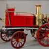
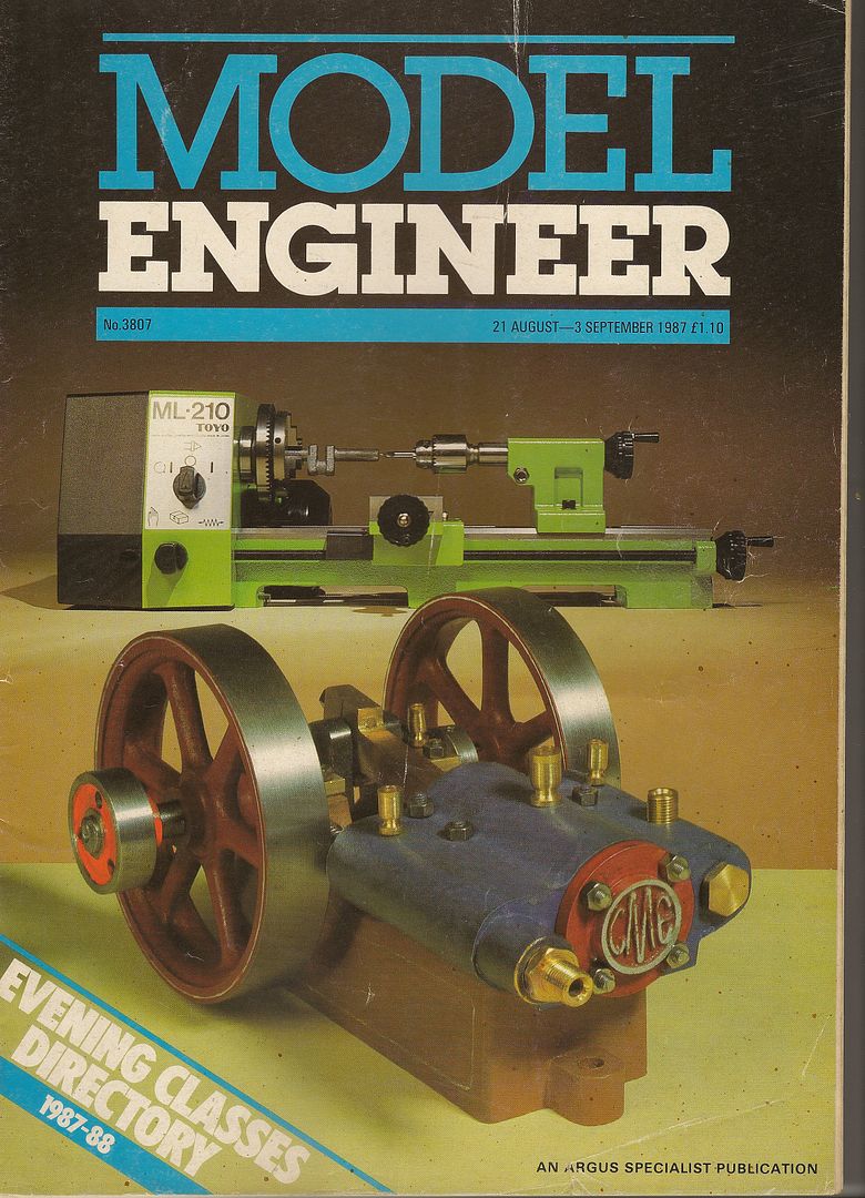
 25215 forum posts 3105 photos 1 articles | INTRO I first became aware of this engine when it apperared on the front cover of Model Engineer Magazine back in 1987 when Stan Bray did a two part construction article.
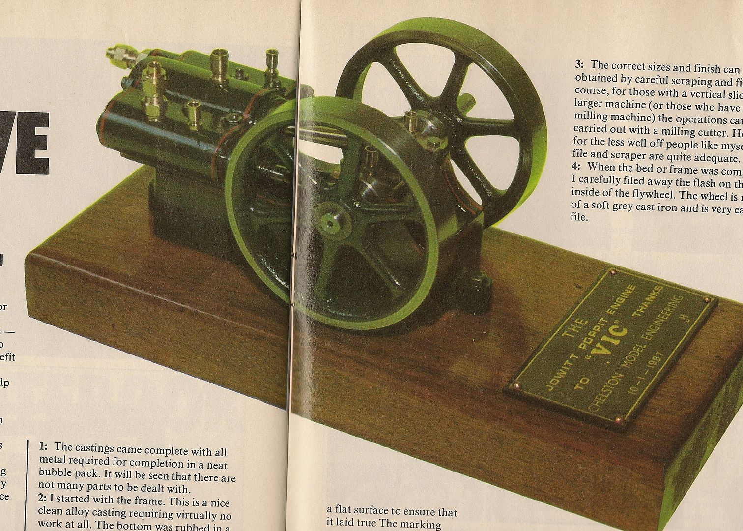
Stan's article was quite short and just gave general discriptions with a few photos but no drawings, this was his version of the engine.
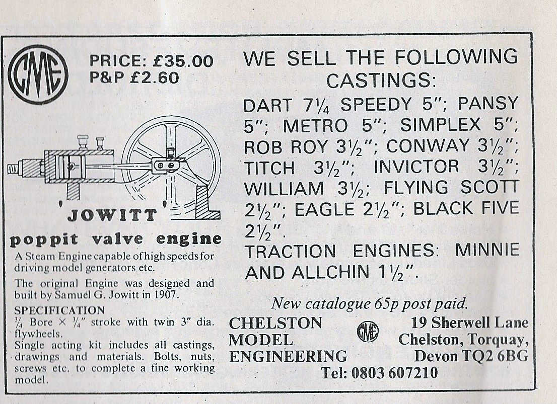
Castings were available at the time but I never got round to buying a set, I think I was part way through my Minnie traction engine then.
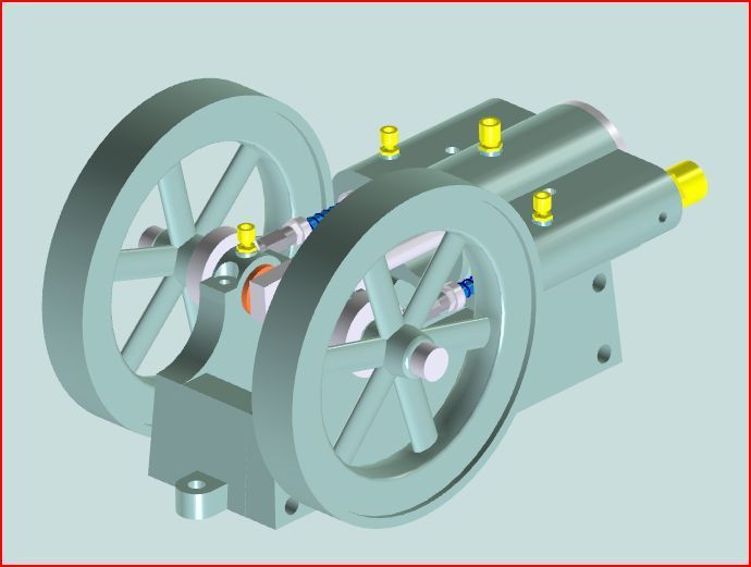
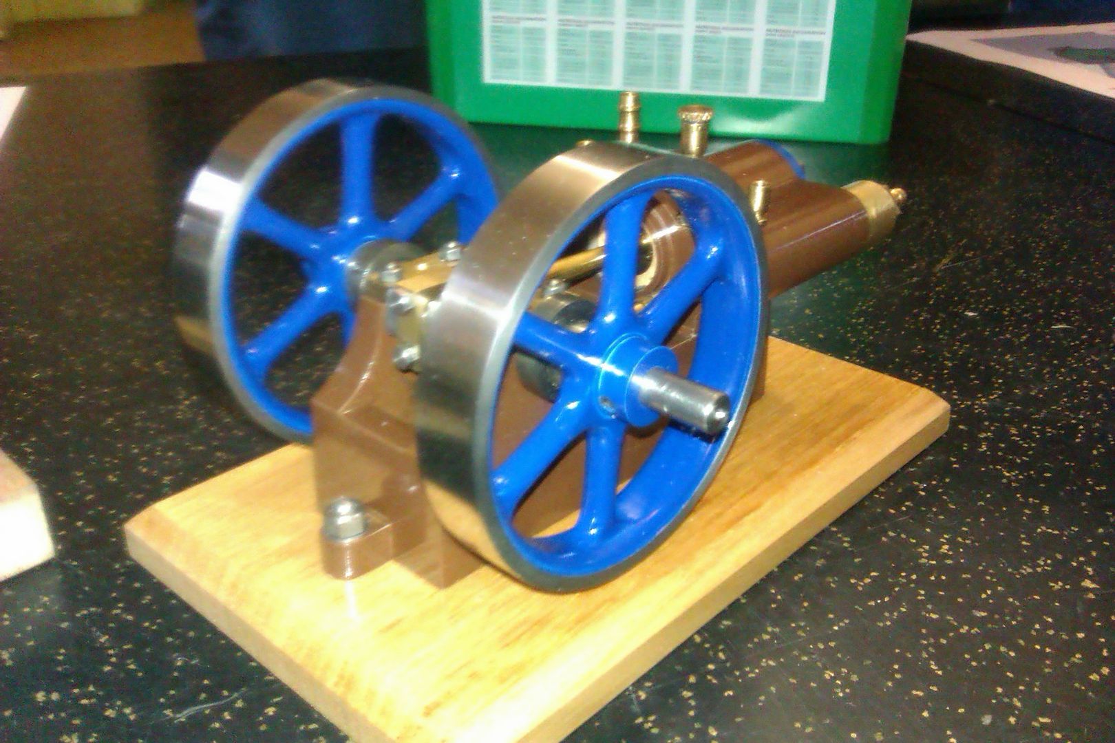
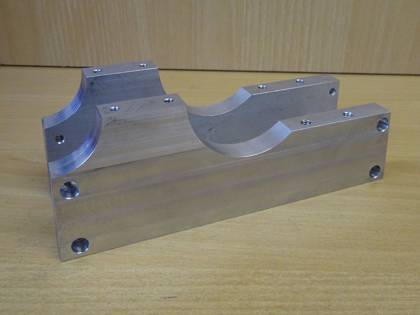
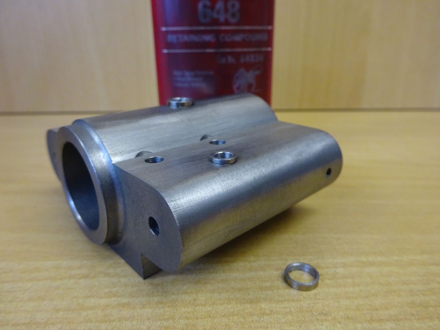
The Jowitt has cropped up on a couple of forums over the years and I have posted the above photos to help people with more info and also mentioned that I would not mind having a go at one as I felt it was something that I could now fabricate due to a few years more experience than I had back then. I was at a meeting of my local traction engine modelers group towards the end of last year and a new member had seen my comments and kindly furbished me with an almost complet set of drawings. So no excuse! A former forum member also kindly shared a photo of a larger older model of the same subject which I have taken some details from As is my usual way I decided to make the model a bit bigger but did show some restraint and settled on an enlargement ratio of 1mm to 1/32" or approx a 30% increase. It would be quite easy for anyone to reverse engineer my version back down to the smaller size if you have limited machine capacity or prefer imperial measurements. This is a proper metric conversion with whole numbers not silly decimals that you get by directly converting imperial to metric. I prepared some drawing using Alibre and started cutting metal on 2nd January, by 31st I had a running engine and a week later it was painted and finished. I have called mine the "Jowitt MkII" and this is the 3D rendering to wet your appitite, next post I will start making swarf and drawings will be included.
Some of the parts could be simplified if you want to have a go but don't feel confident of things like shaping the cylinder or the angled cuts to the base and I will point these out as I go along. There are also other ways that most parts could be made, I have used whatI have but feel free to ask if you don't have some of the equipment that I show. This is an interactive PDF so you can play about with teh sketch, may not work on a mac and you may need to trust the document. J
Edited By JasonB on 07/02/2016 20:21:42 |
| ian j | 07/02/2016 20:12:46 |
 337 forum posts 371 photos | Jason. Looking forward to your next post. This looks like a good build project for me ? Ian |
| duncan webster | 07/02/2016 20:15:26 |
| 5307 forum posts 83 photos | Looks good to me, will the 3D model work in Inventor? #2 son has access to this at work. |
| JasonB | 07/02/2016 20:22:59 |
25215 forum posts 3105 photos 1 articles | Duncan I have added a link that should work on a PC, drawings will be in pdf format. |
| steve de24 | 07/02/2016 22:13:11 |
| 71 forum posts | Jason, I'm looking forward to reading this build thread. Thanks for posting. Steve
|
| JasonB | 11/02/2016 20:25:30 |
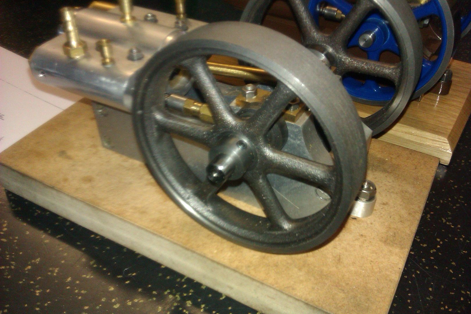
25215 forum posts 3105 photos 1 articles | I have just received some additional information that Chelston Models also produced a larger version of this engine called the Jowitt Major but no other details about size etc. The Model Chelston offered this with the base, cylinder and flywheels in cast iron the later of which were identical to Stuart 10 V/H flywheels and the extruded bearing material looks to have come from the same source. This engine is from the castings and made by Norman Peach who helped me with the drawings.
He also had a scratch built one with Aluminium base & cylinder and had used Stuart Flywheels & bearing material
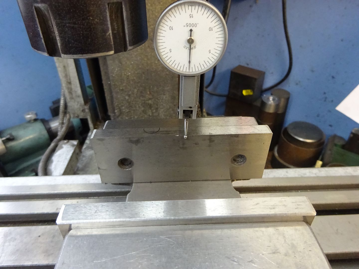
I decided to use a block of cast iron for the cylinder as I had some to hand though Aluminium should be upto the job if you like to keep your hands clean. The two flywheels came from Reeves and are their "Perseus" ones which clean up easily to the required 97mm of my larger version. Frame Sides As a lot of the set up will use fixed jaw of the vice as a reference its as well to check it is true to the Y-axis before starting.
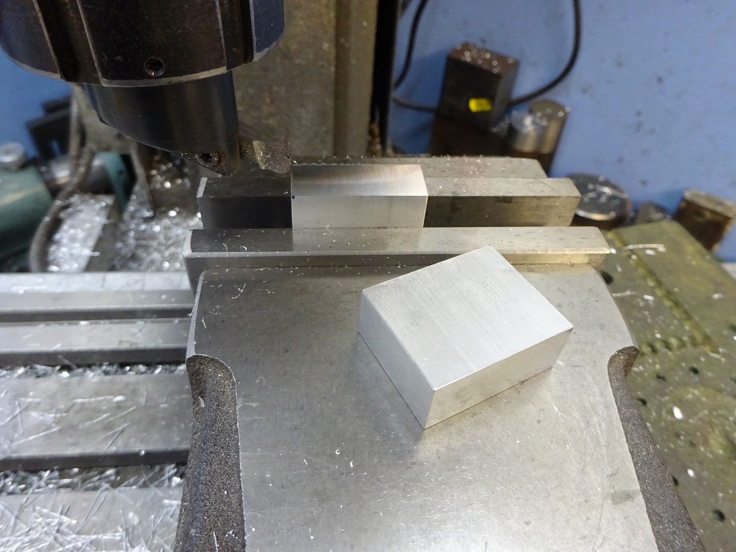
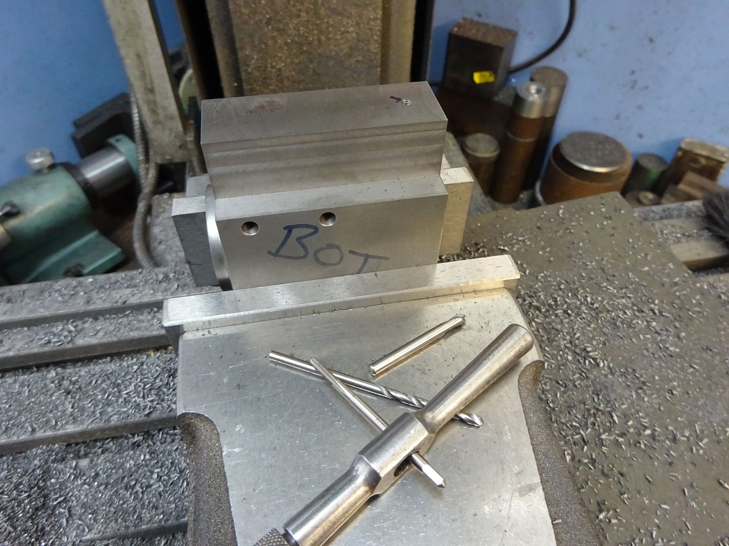
The first job is to saw off two pieces of 2" x 0.5" aluminium a little over the required 140mm, set it in the vice on parallels and square up one end of each.
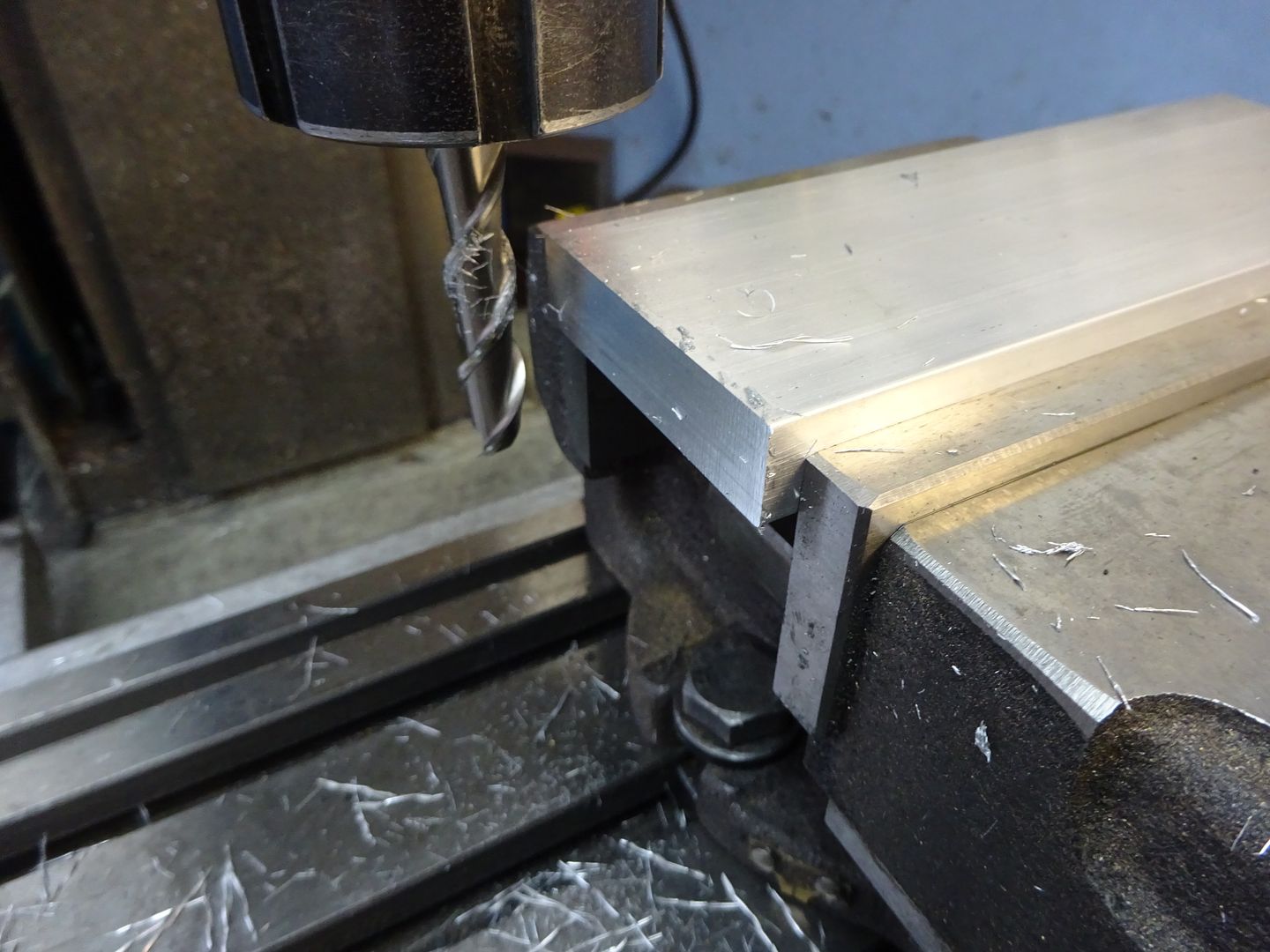
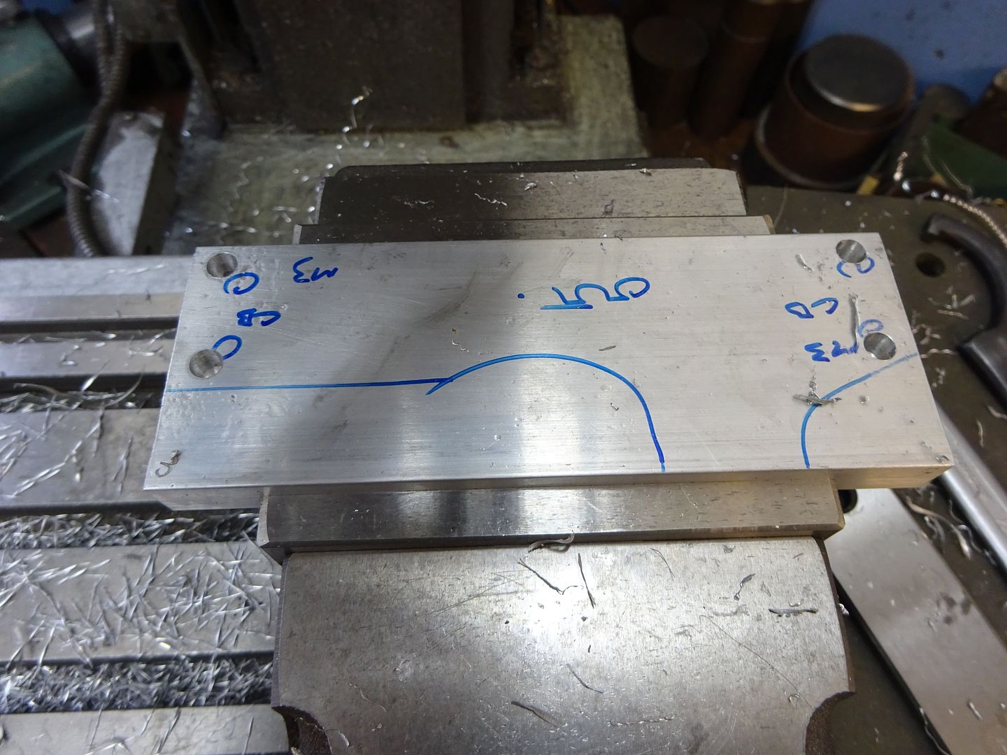
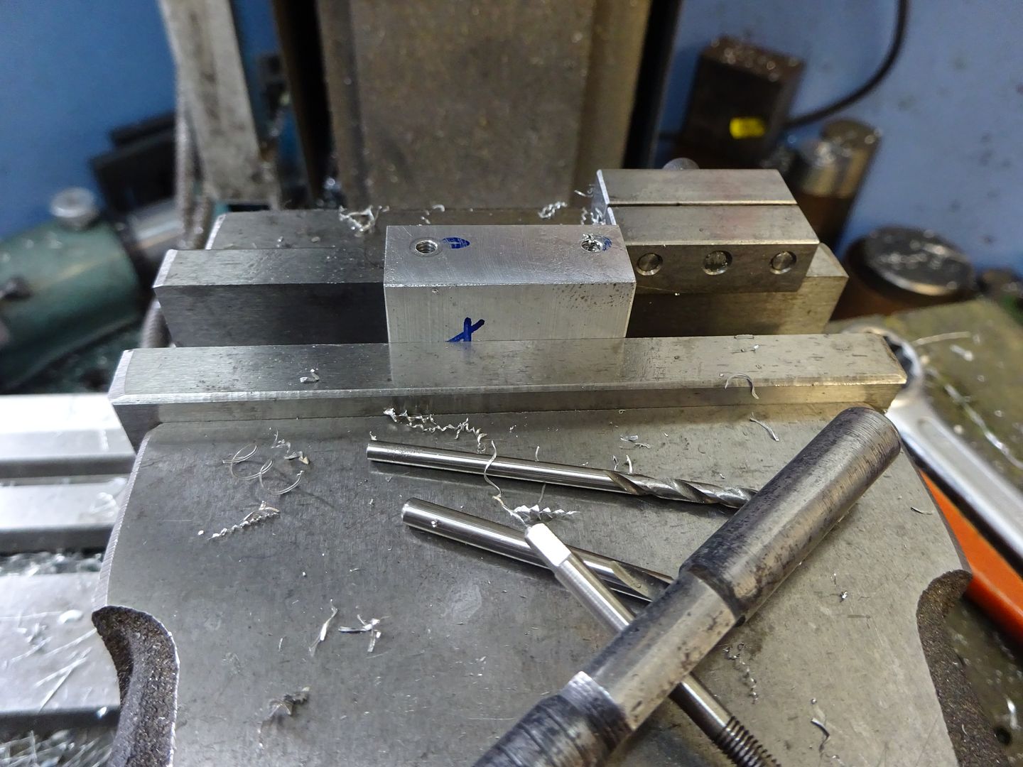
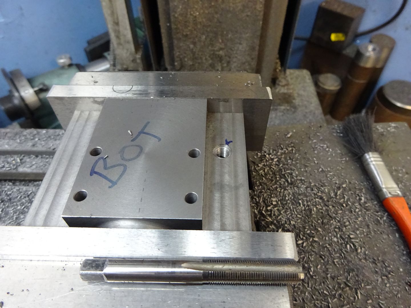
As the two sides are mirror images of each other it is easier to do most of the machining with the two pieces screwed together. After roughly sketching out where the holes & cuts go with a marker I set one side in the vice and used an edge finder to locate the bottom and previously squared end. The four M3 clearance holes can then be drilled and counterbored in one side, I set the holes 0.5mm higher than drawing to allow a skim to be taken off the bottom of teh extruded bar. If you don't have a counterbore then a 6mm milling cutter can be plunged in or an old drill reground to give an almost flat bottomed hole. For the other side just drill two opposite holes clearance but tap the other two M3 which will allow the parts to be screwed together without the need for nuts sticking out the sides. You can see I have writen M3 against the ones to tap.
With the two plates stood back to back on a flat surface a couple of M3x12 cap head screws can be used to hold them together, then hold them in the vice bottom facing upwards and skim 0.5mm off to level the two surfaces and bring the screw holes to the drawing dimension of 5mm from the bottom. With that done grip them up the right way and mill the top down until you reach the required 50mm overall height. I used a flycutter for this but a couple of passes with a milling cutter will do.
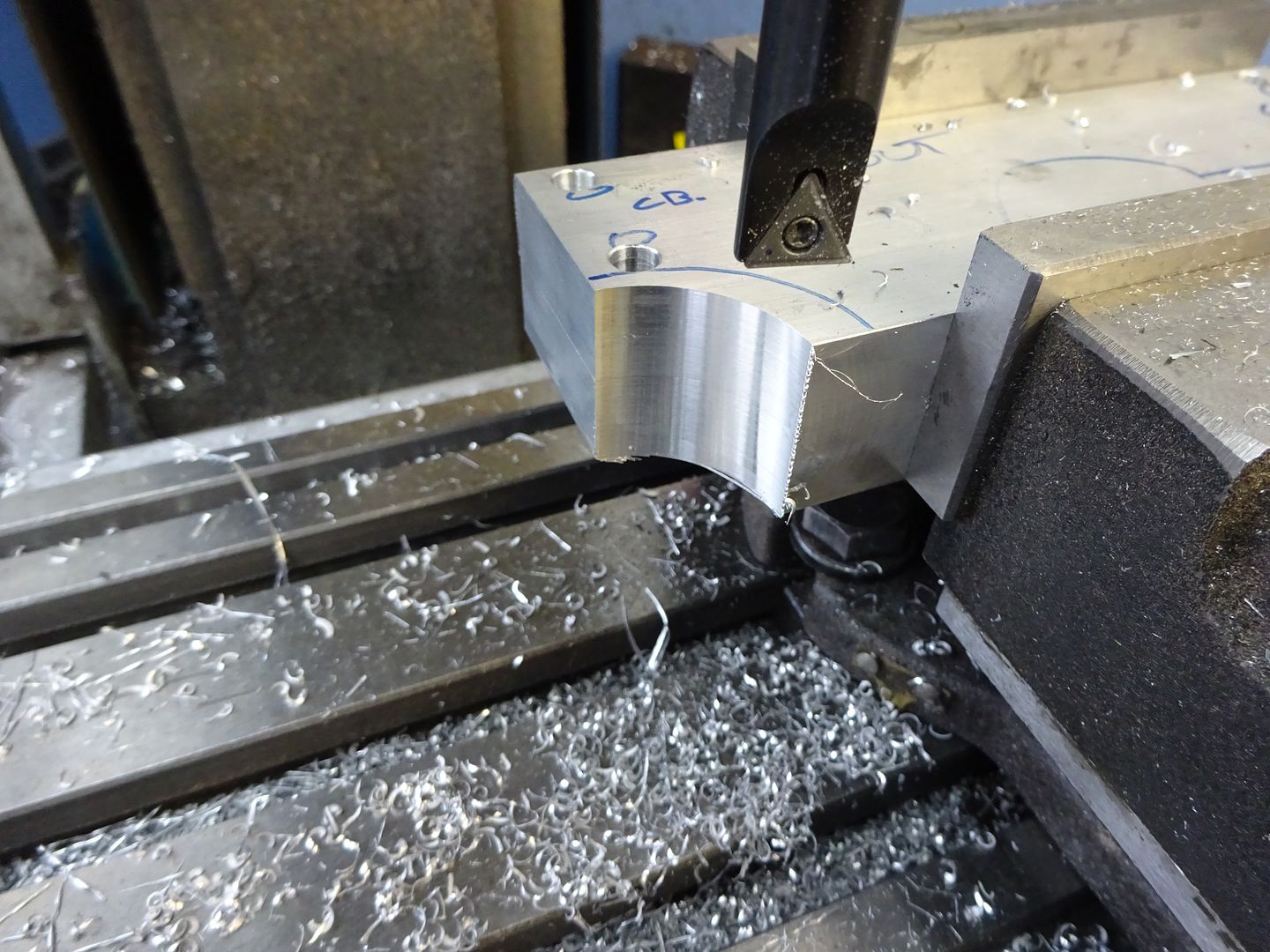
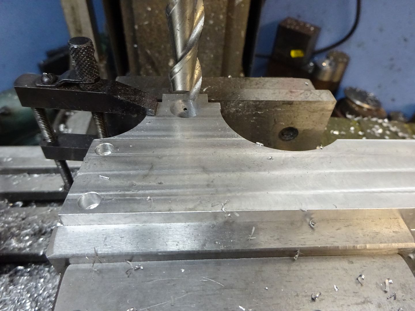
The curves that form the raised area for the crankshaft bearing can be formed with a boring head. Move the mill table so the spindle is 18mm away from the end of the work and then adjust the position of the cutter until it just kisses the end as you rock it back and forth by hand, this is an easy way to set the required 18mm radius.
With the spindle 50mm from the vice jaw datum (bottom of frame) make a series of plunge cuts in 1mm steps until the spindle is 2mm in from the end of the work.
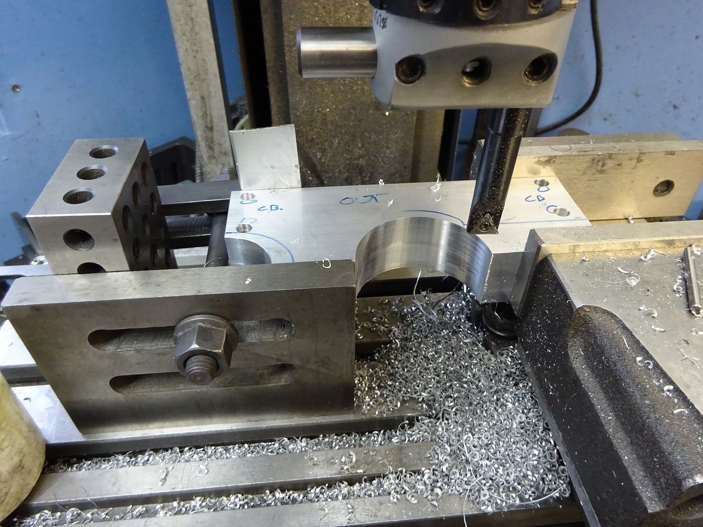
A similar method is used to set the radius on the other side to 24.5mm and the larger radius cut in the same manner.
These two curves could be sawn & filed if you don't have a boring head. to be continued Edited By JasonB on 11/02/2016 20:27:23 |
| JasonB | 11/02/2016 20:31:28 |
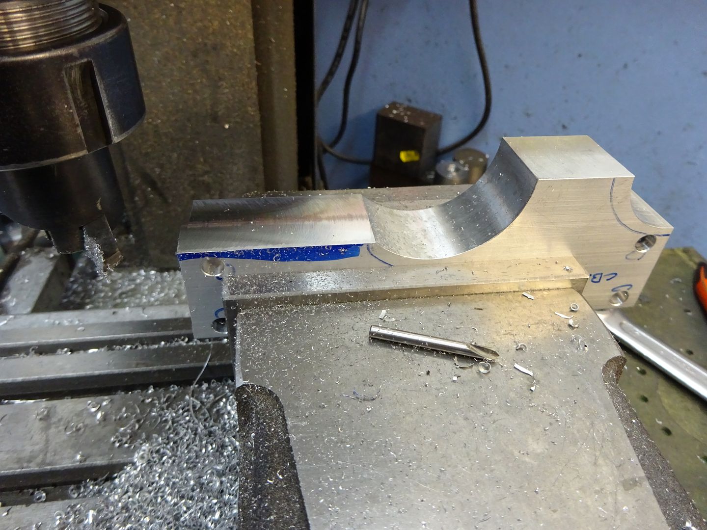
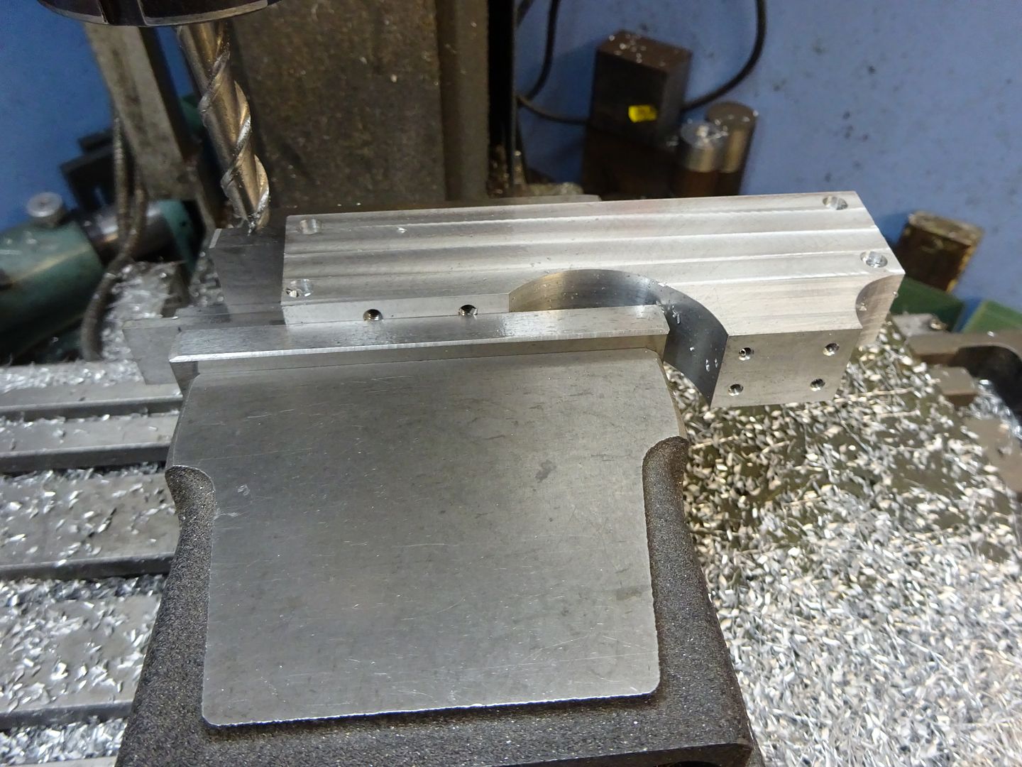
25215 forum posts 3105 photos 1 articles | Frame sides continued Scribe a guide line where the cylinder will sit 32mm up from the base and saw off the waste material leaving a mm or so to cean up on the mill. Save the two pieces that are cut off as they will do for the bearing caps later. Set up in the mill and machine until the required 32mm finished height is reached.
Locate the end of the frames and find the centre line of the pair using an edge finder and then drill and tap for the bearing caps and cylinder mounting studs. Note that the bearings are 5mm from the inside edge of the frames (ctr of pair) and the cylinder studs 6mm.
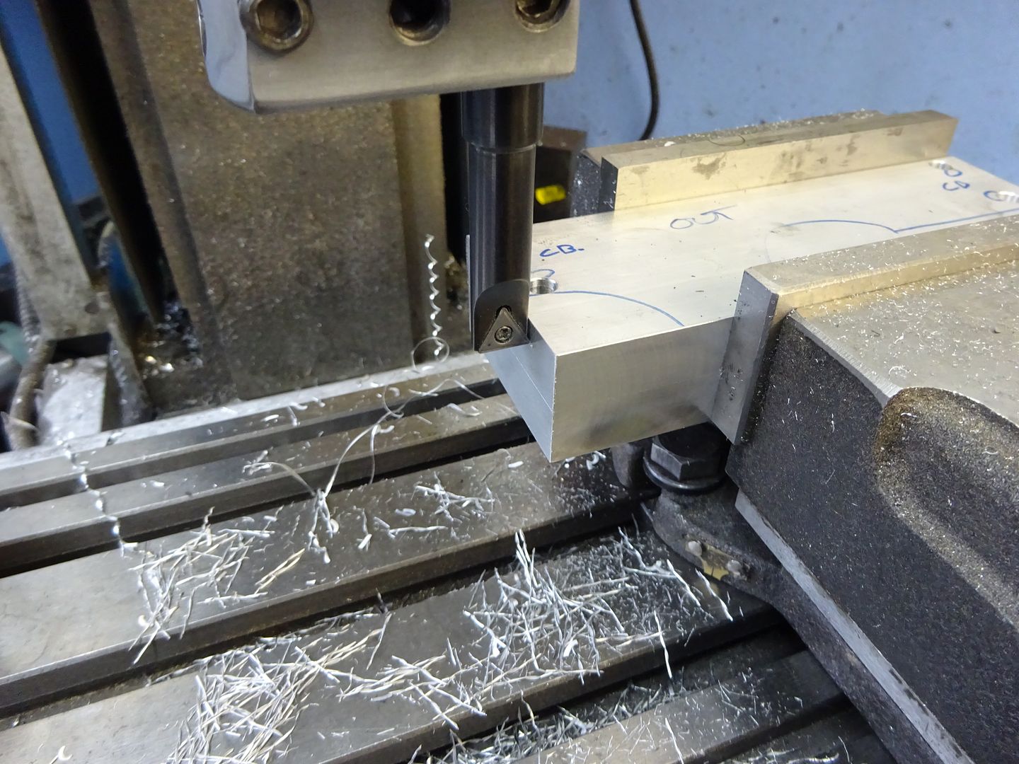
At the same setting the two vertical edges around the bearings can be reduced to the finished 10mm width, I used a 10mm dia cutter so it was simple to set the spindle 15mm from centre for the final cut. I took full 18mm depth cuts 0.5mm per pass using one of ARC's HSS cutters for Aluminium which romped through the metal.
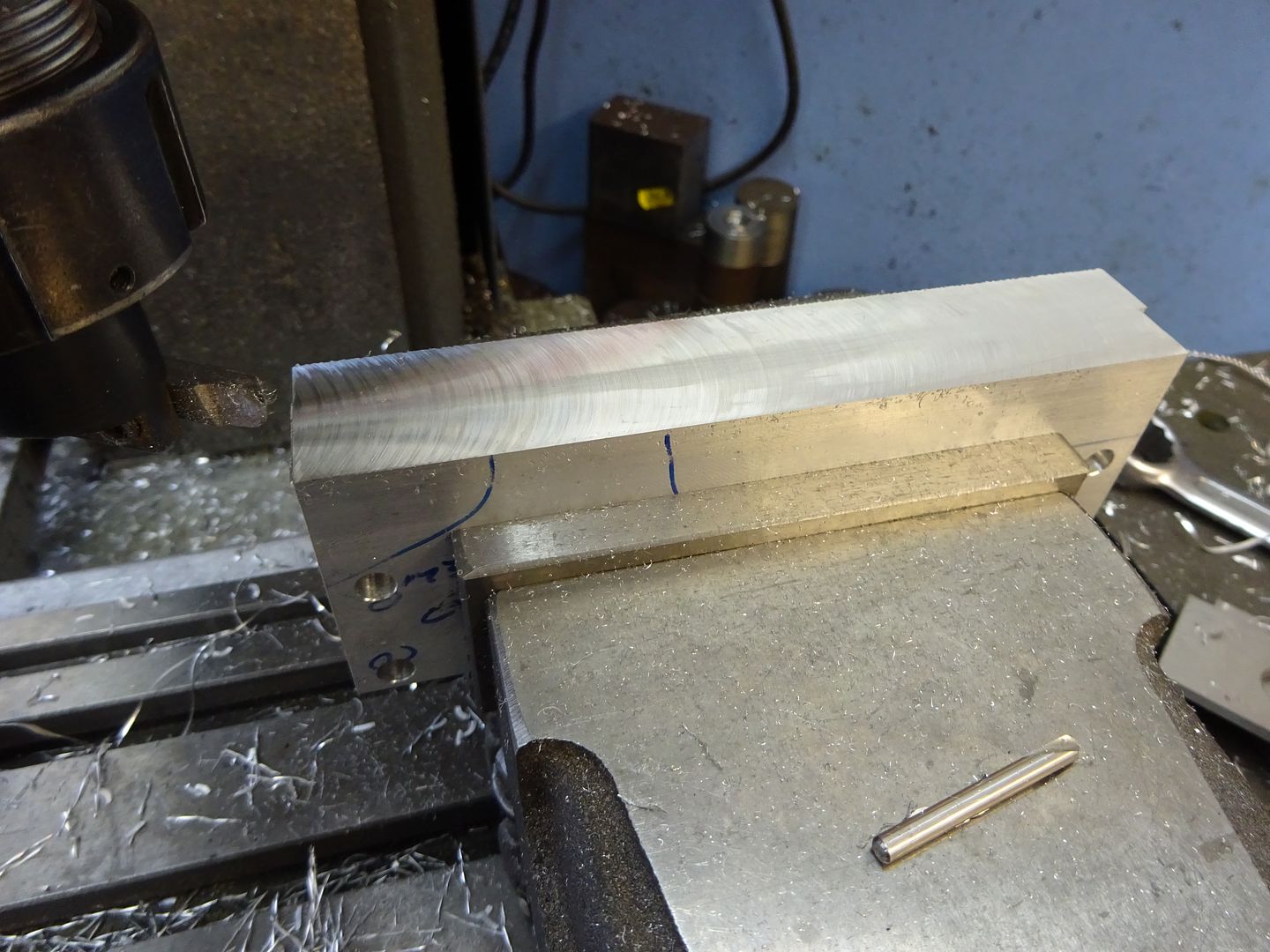
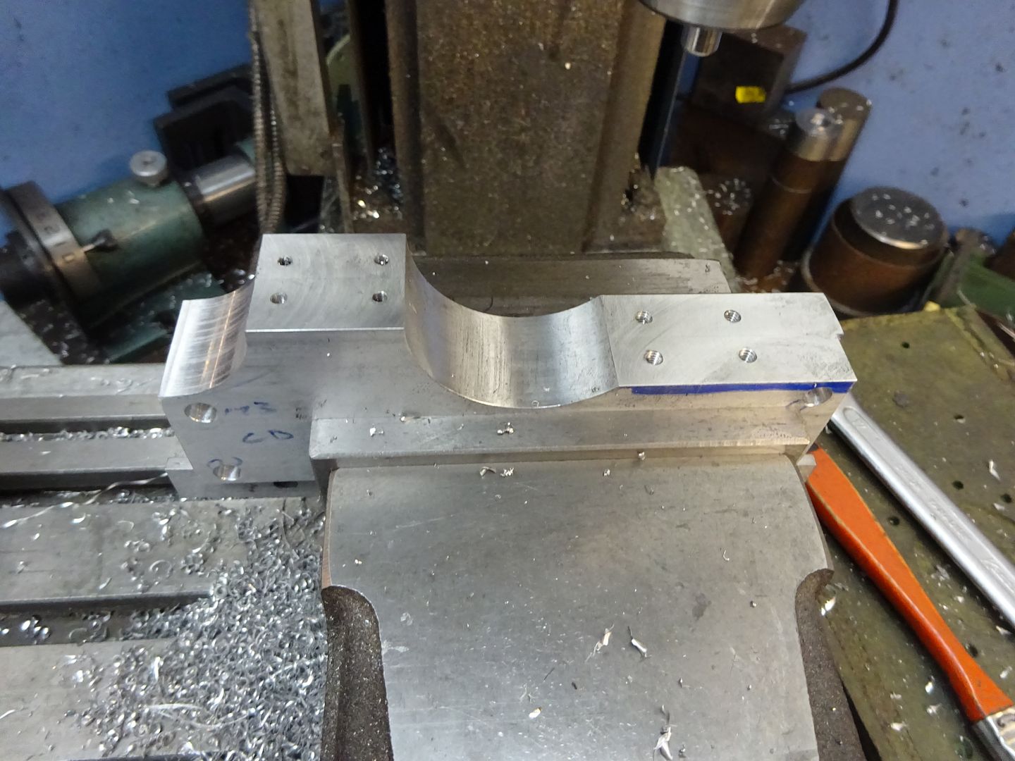
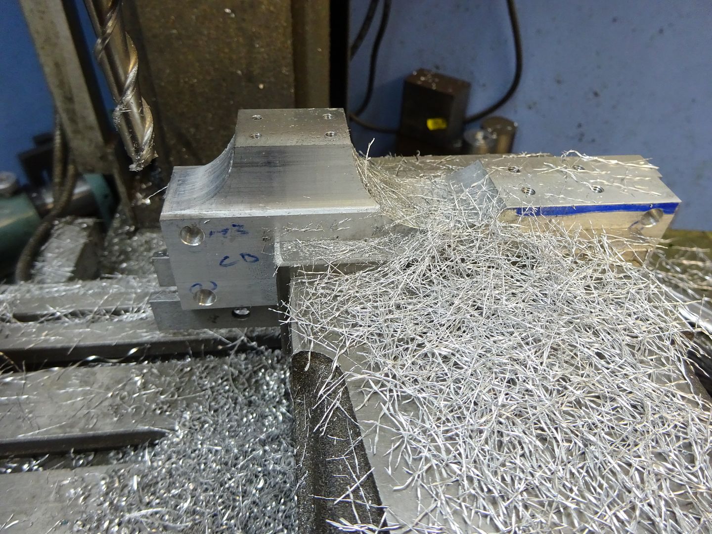
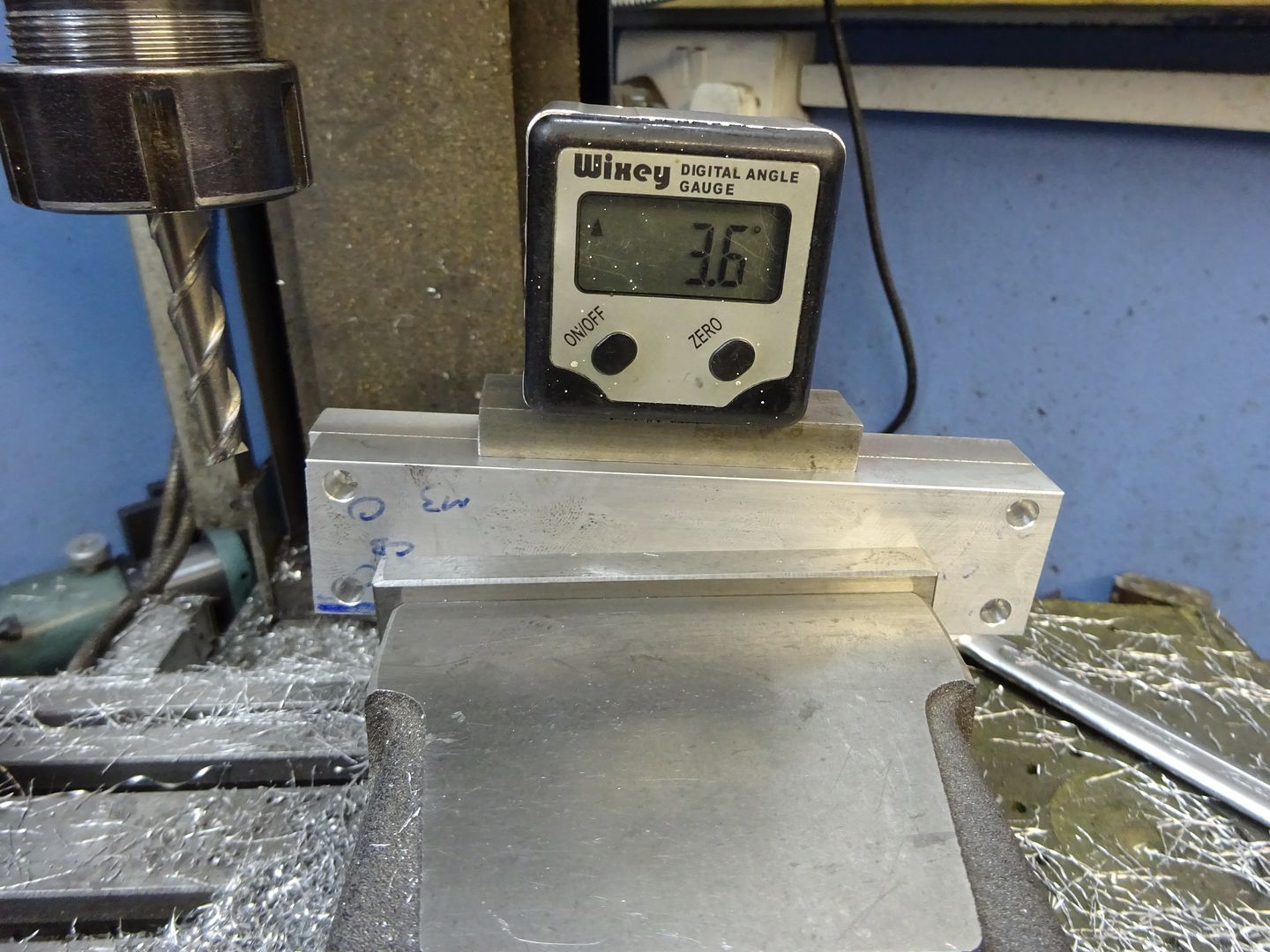
With the side frames upside down and held at 3.6deg the sloping ends can be cut and the overall length brought down to 140mm at the base.
I don't have a tilting vice but its easy enough to pack up one end of a standard vice and then lightly bolt back down to the table to avoid distortion. The slope on the sides can then be milled to the same 3.6deg angle aiming to get a smooth transition where it meets the vertical face .
That is the side frames done, the pin hole to stop the bearings rotating will be drilled later
If you feel the sloping side may be a bit beyond what you are capable of then 10mm material could be used and the base done with straight edges. Next time I will cover the frame ends and feet. J Drawing to download If anyone finds errors on teh drawings please let me know so they can be corrected |
| JasonB | 18/02/2016 17:42:26 |
25215 forum posts 3105 photos 1 articles | Frame Ends Start by machining two pieces of aluminium to 32 x 26 x 12mm
Locate the far edge and right hand end then move in 5mm and drill and tap M3, move along 22mm and do the other hole. If you use a vice stop then the other three pairs of holes can be done without having to locate the edges each time
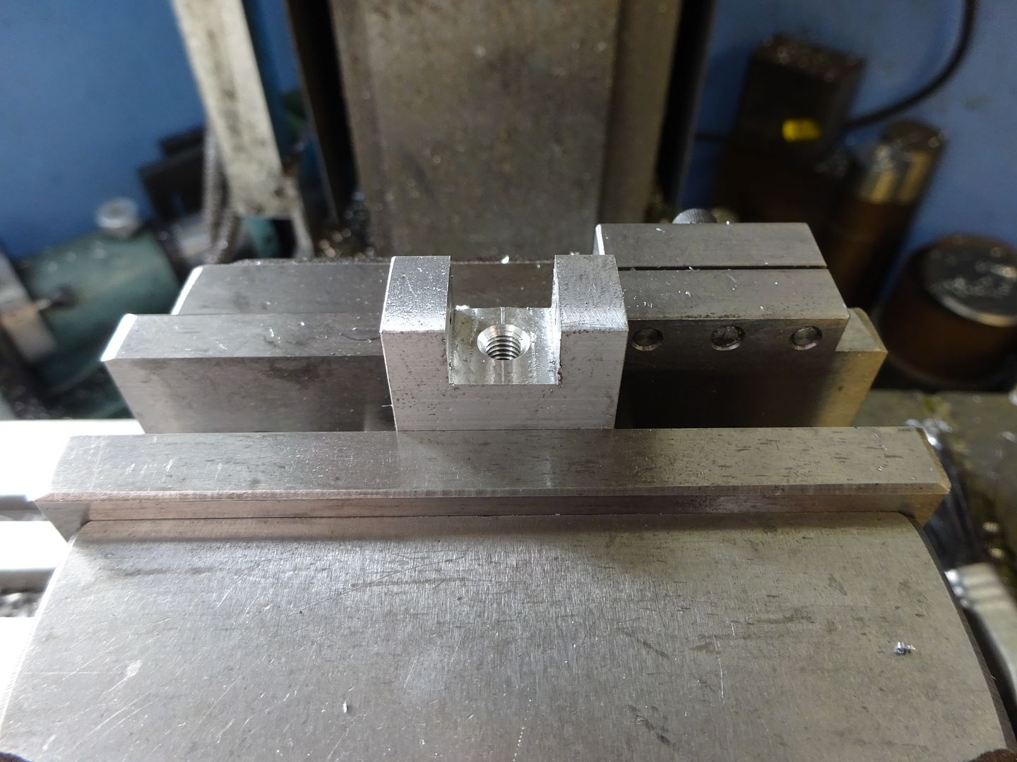
With the vice fixed jaw and stop still clocked in the bottom slot is easily located and using a 12mm dia cutter taken to 8mm deep followed by drilling & tapping for the M5 thread.
Next set the ends to 3.6degrees and flycut or mill the slop on the outside face to complete
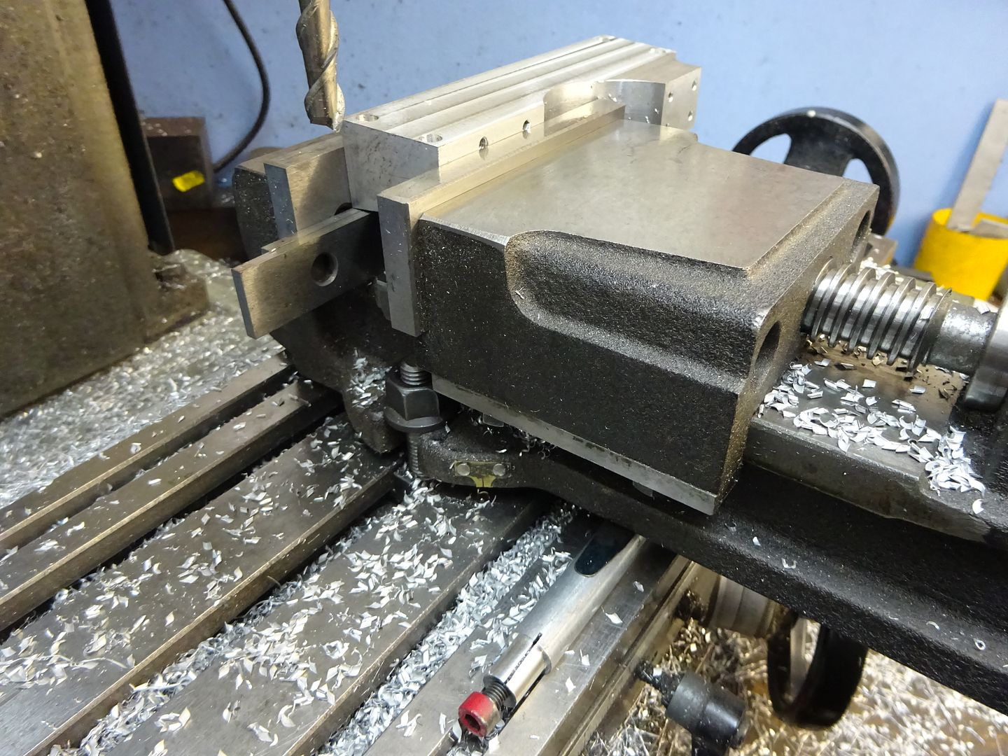
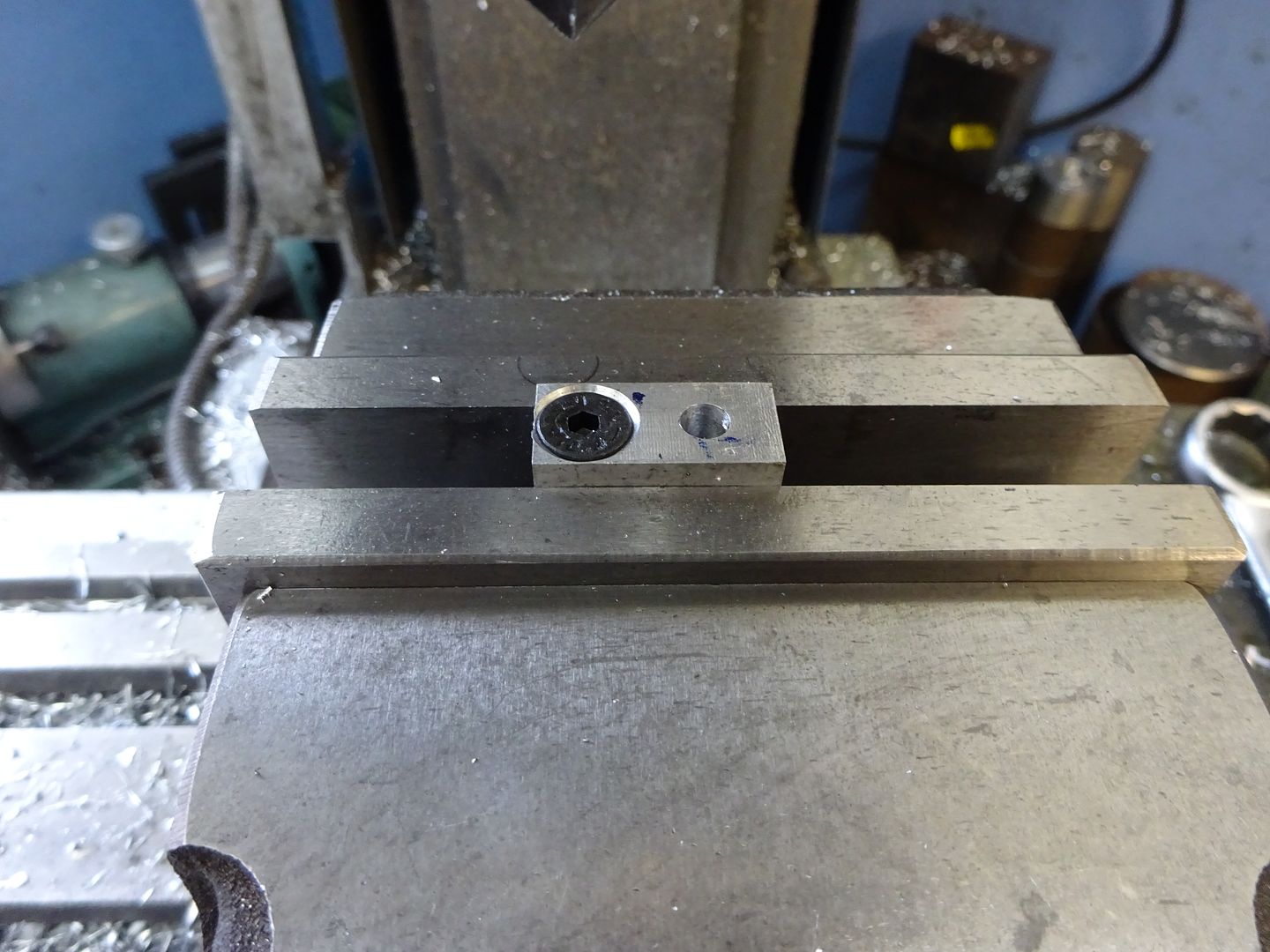
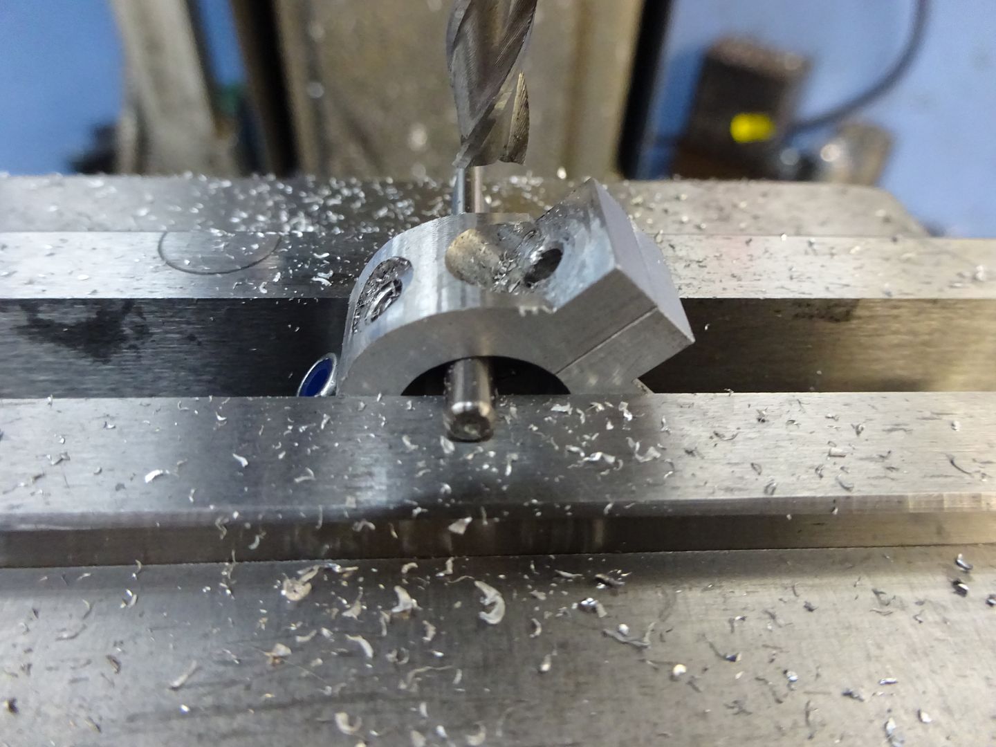
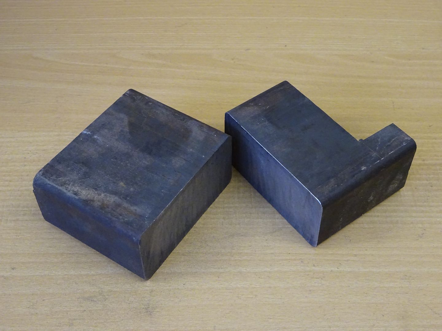
Feet Machine two bits of Aluminium to 12 x 8mm and at least 24mm long, locate an edge and end then drill the two 5mm holes countersinking one to take the head of an M5 CSK socket screw.
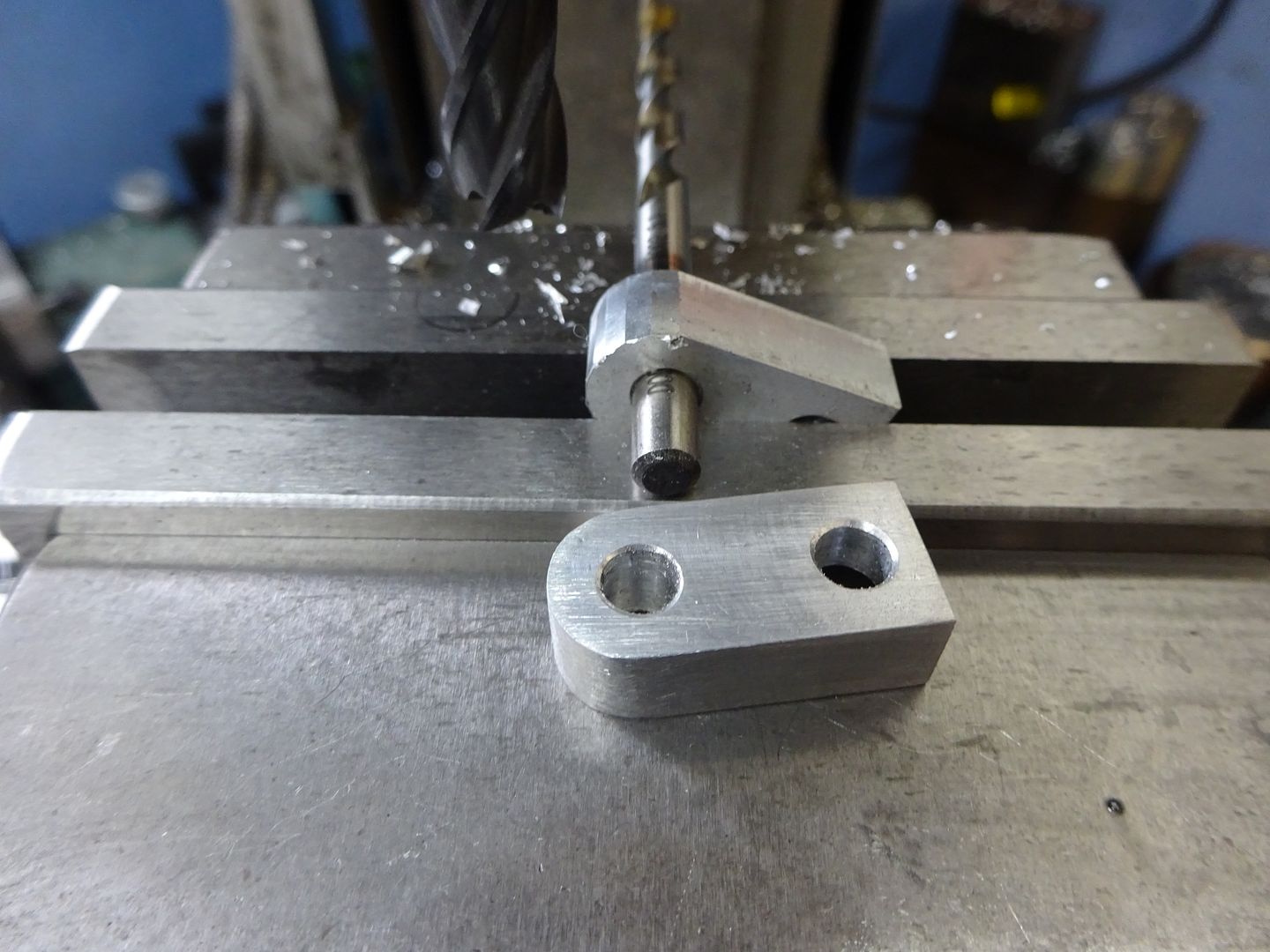
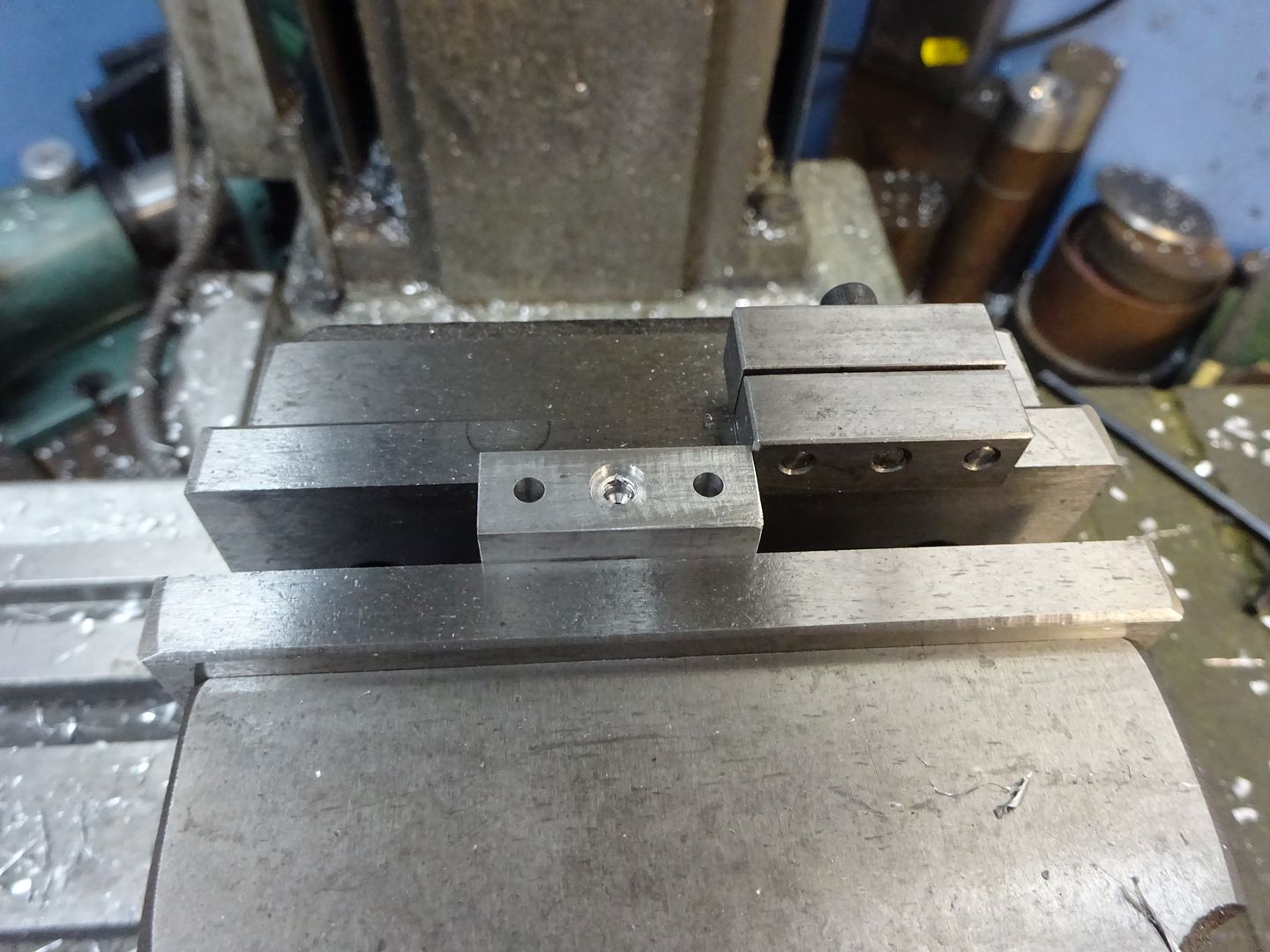
Pop a 5mm pin into the hole and set a milling cutter 8.5mm above the vive jaws and then take a series of tangental cuts which will leave a facetted face as seen on the one in the vice. This can quickly be cleaned up with a file to leave a nice smooth curve as in the foreground.
A few M3 and M5 screws can be used to see how it all goes together, don't drill out the M3 threads in the side plate to clearance yet. J |
| JasonB | 23/02/2016 20:35:58 |
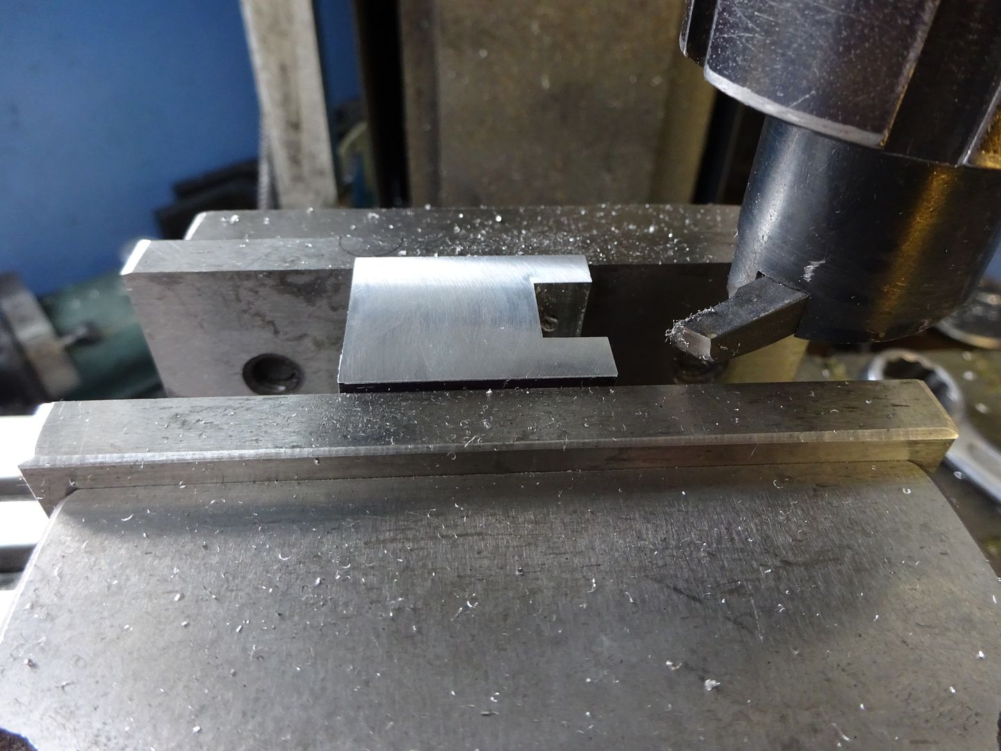
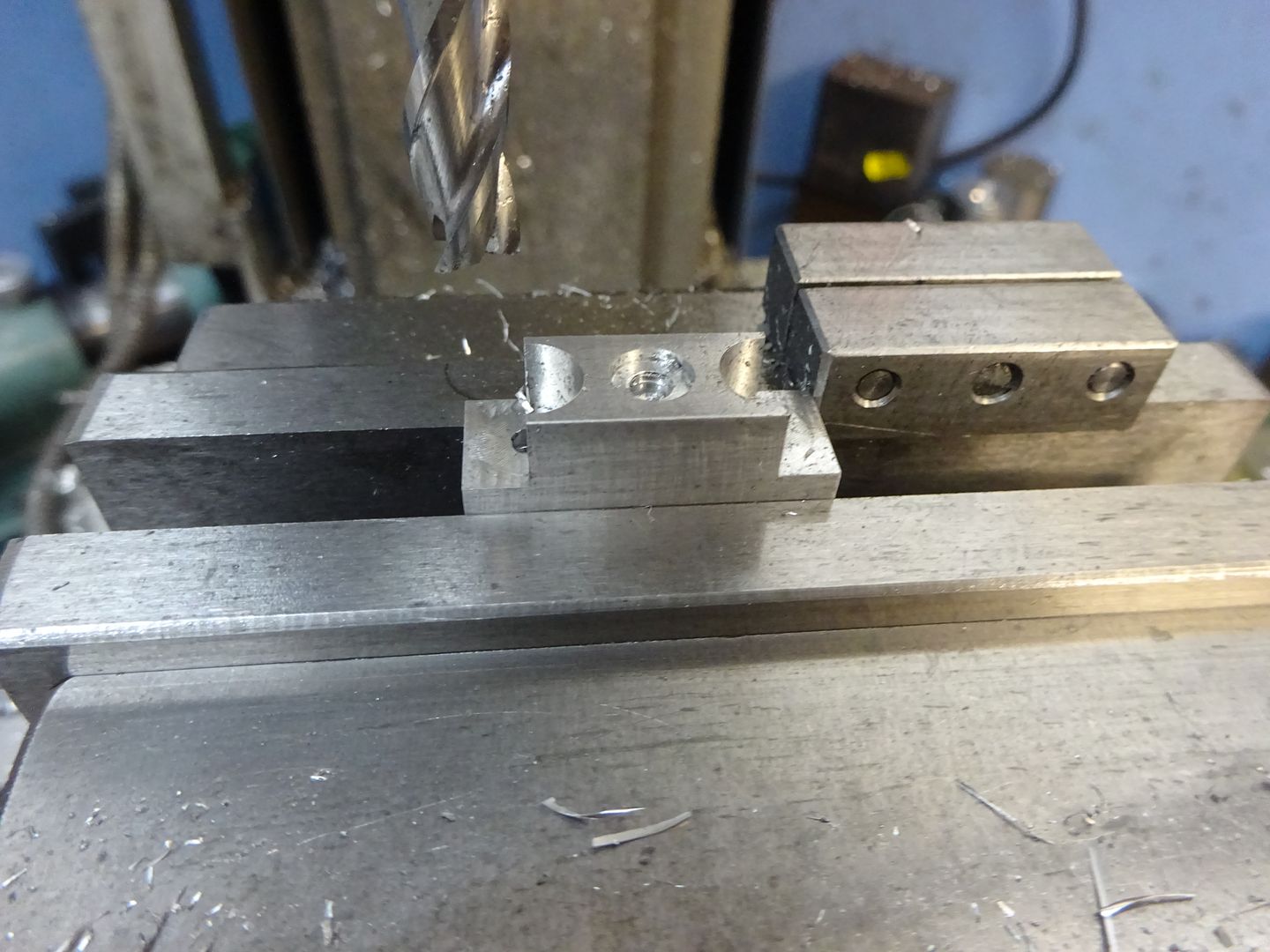
25215 forum posts 3105 photos 1 articles | Bearing Caps Start by machining two pieces of aluminuim to 10 x 10 x 28 and then hold in the vice and locate a side and end. Drill the two 3mm holes then the 1.5mm oil hole right through followed by a 6mm 2 or 3 flute cutter plunge 3mm deep to cut the socket for the bush.
Changing to an 8mm cutter plunge 6mm deep to form the counterbore to the 3mm hole and then the flat area 4.8mm in from the end.
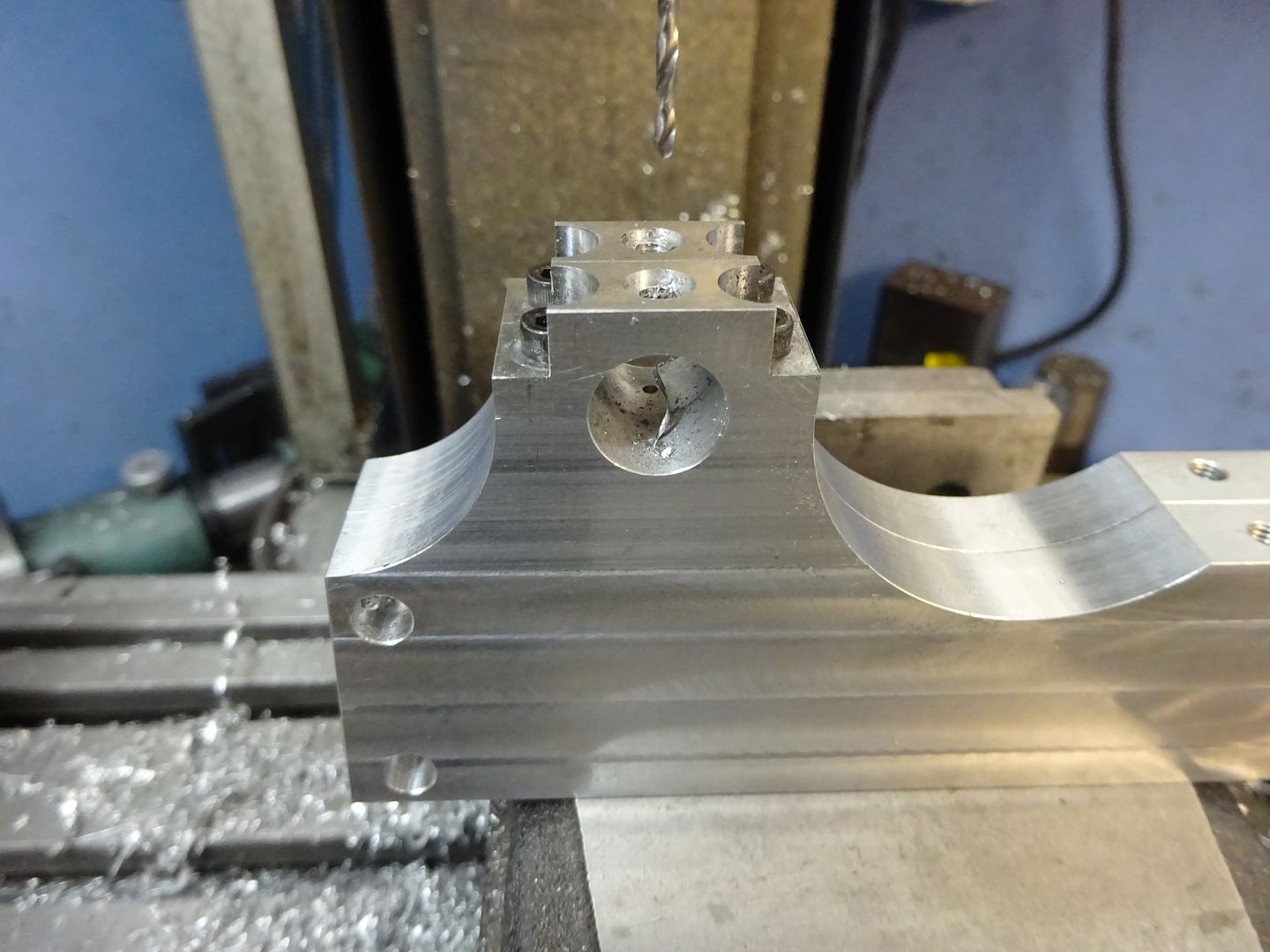
The two side frames can now be screwed back together and the caps screwed into place. Locate the centre of the crankshaft hole, spot drill then open up with 6mm and 10mm drills and finally use a 12mm milling cutter to take the hole to size.
With the frames stood upright the 1.5mm holes for the bearing retaining pins can be drilled using the matching hole in the cap as a guide. Mark the caps before removing so you can assemble them in the right position in the future.
Using the same method as for the feet the tops of the caps can be rounded over to 10mm radius
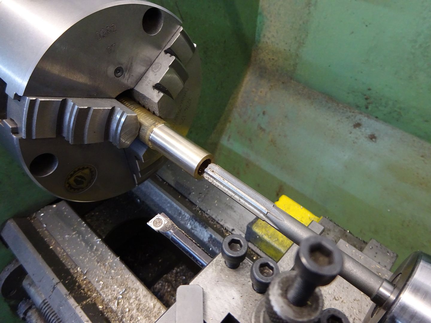
Oiler Bush These are simple turning jobs from 6mm rod. Face the end, drill 3.5mm and tap M4 x 0.5 metric fine then part off two 5mm lengths. If you don't have metric fine then 5/32 x 40 ME or M4 x 0.7 will do. These bushes can be fixed into the bearing caps with Loctite or JBWeld Main Bearings Turn down enough material for two bearings and parting off allowance to 15mm. Face off and drill in stages to 9mm, bore out to 9.8mm and then ream to 10mm.
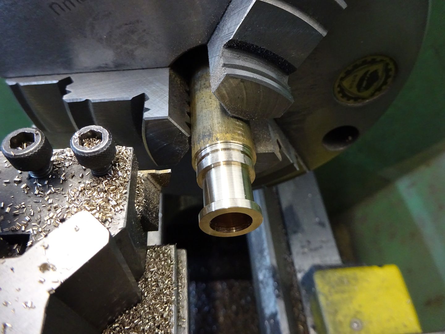
Use a parting tool to cut the 12mm dia waist groove 10mm wide and then part off, repeat for the second bearing.
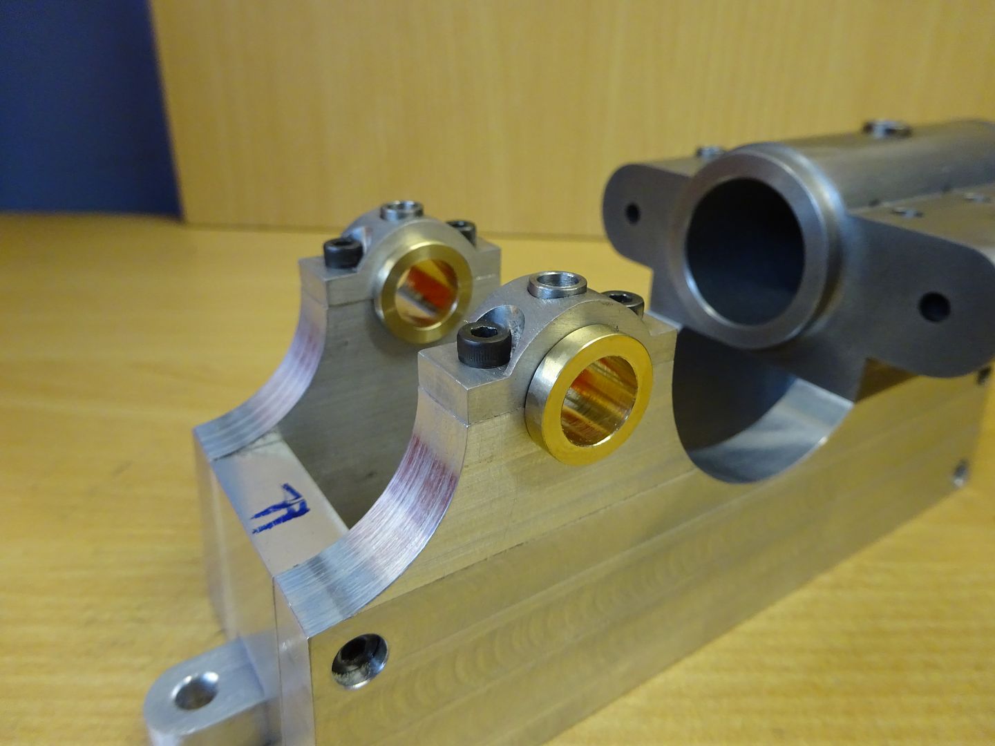
And a quick try out to see how these parts go together.
Edited By JasonB on 02/03/2020 18:21:44 |
| JasonB | 01/03/2016 19:35:38 |
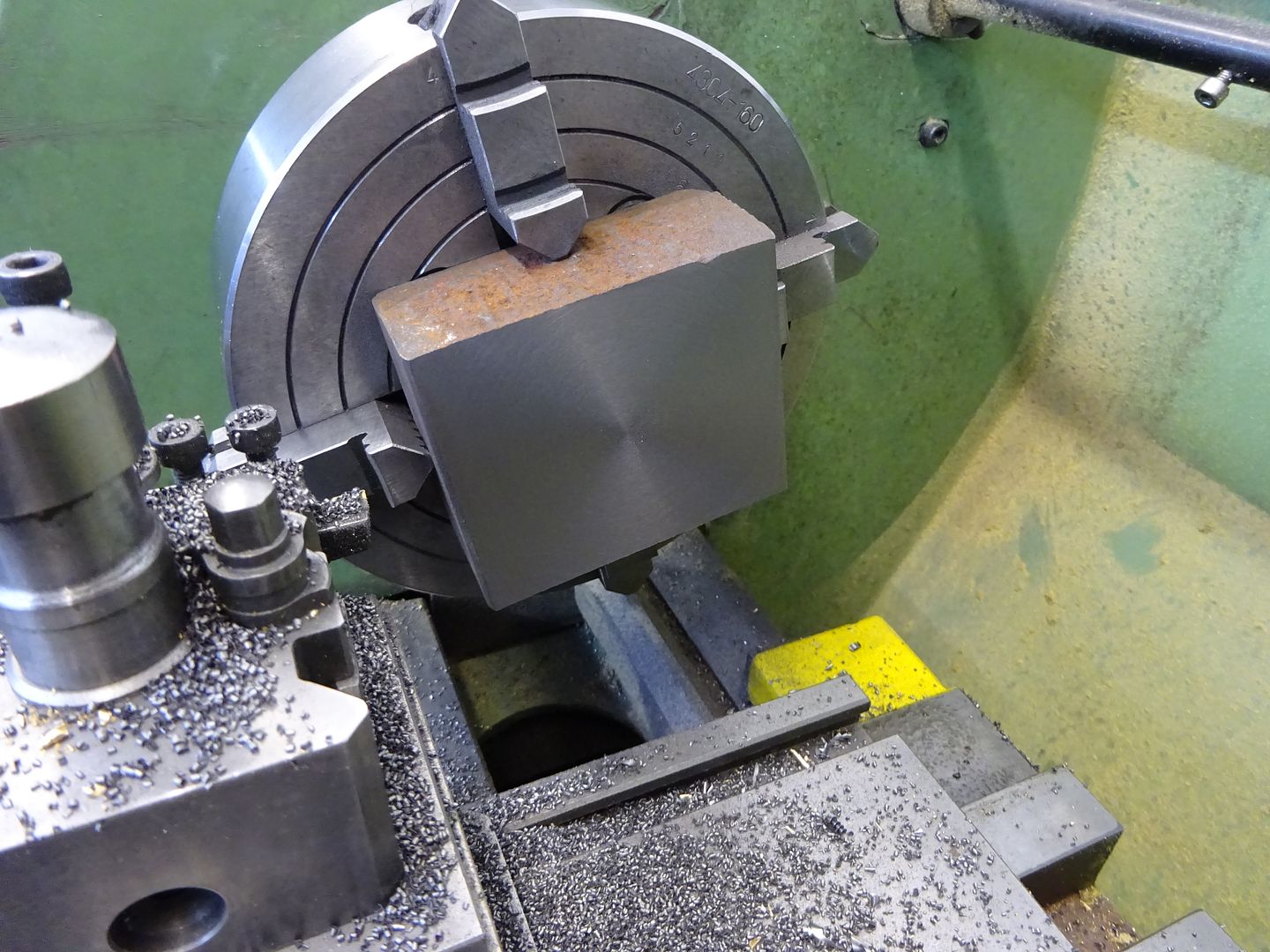
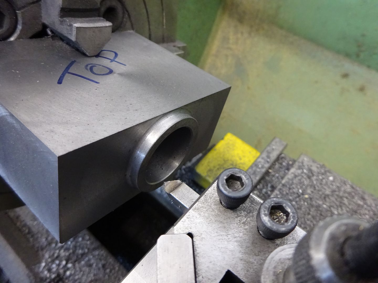
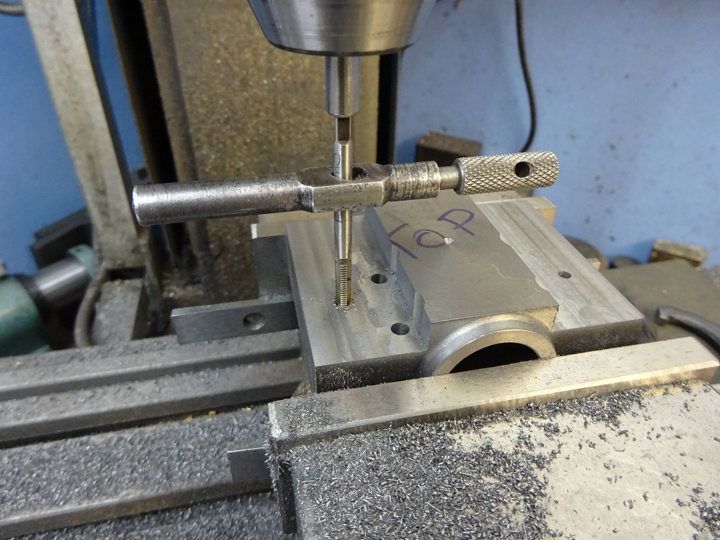
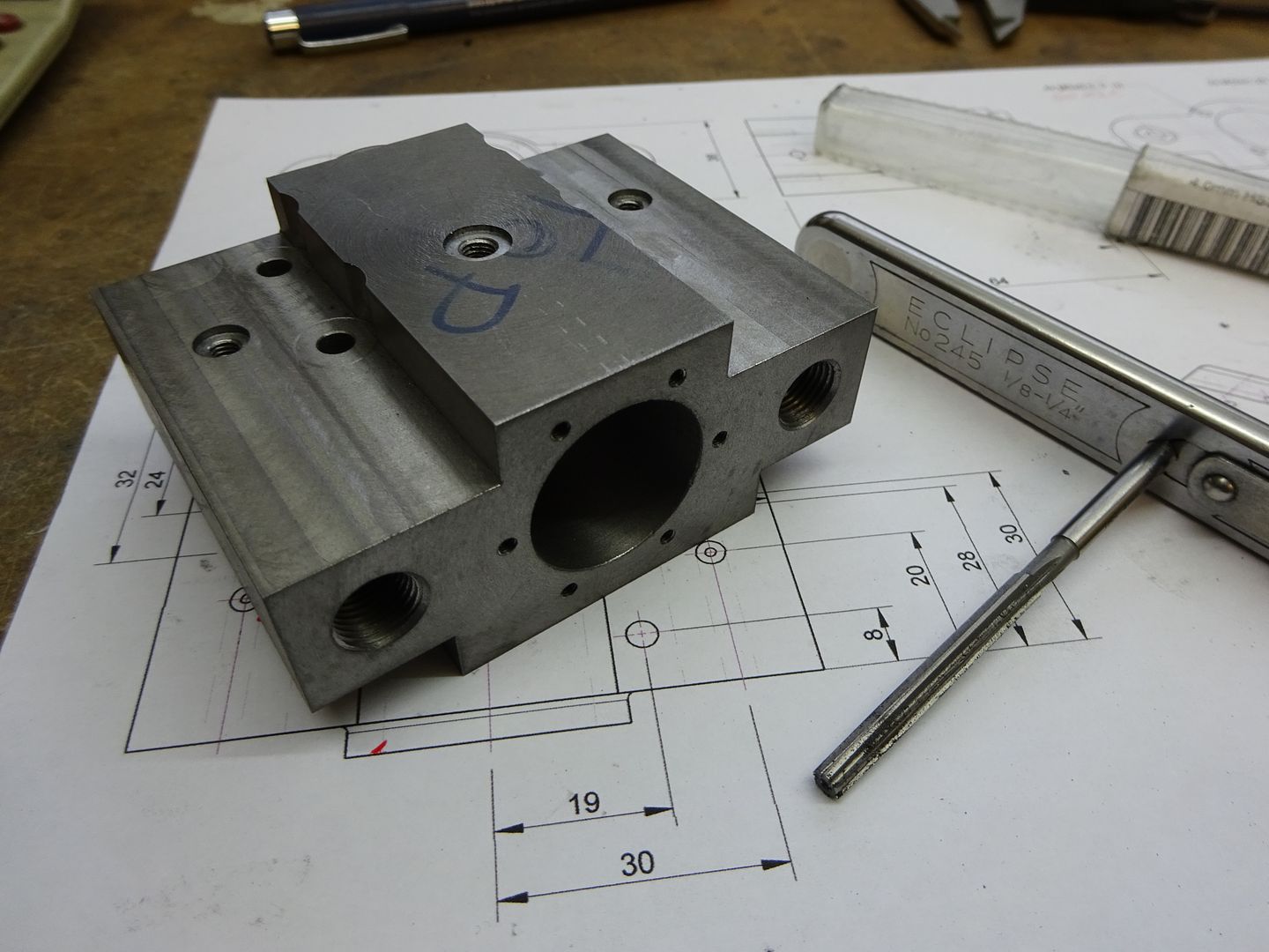
25215 forum posts 3105 photos 1 articles | Cylinder Probably the most involved part on the engine, if you don't feel upto it then the curved top and sides could be left square so you have a + shaped cylinder or even just leave it as a rectangular block. I used and have shown Metric Fine threads on the drawings but ME 40tpi or even standard Metric Coarse could be used if you don't have the fine series taps & dies The cylinder can just be got out of a piece of 40x80 cast iron bar as it comes out a little over these nominal sizes. I started by sawing off a lump with enough allowance to clean up to the required 64mm length.
Next the top and bottom surfaces were cleaned up on the lathe taking similar amounts off each to reach the 36mm finished thickness.
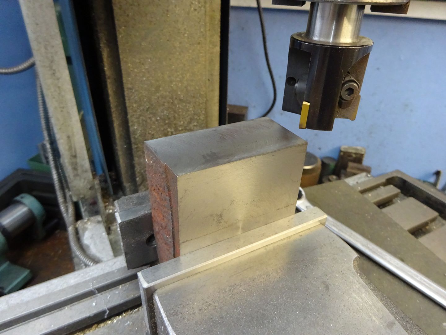
Then over to the mill to take a light cut off one edge
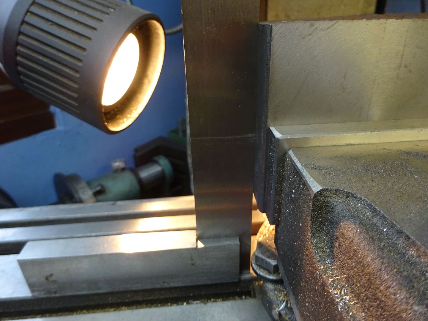
Then rotate the work 90 degrees in the vice and using a square make sure the first edge is true, a light behind helps to see any gaps. Once set the second edge can have a light skim. followed by the other two to bring the block down to size.
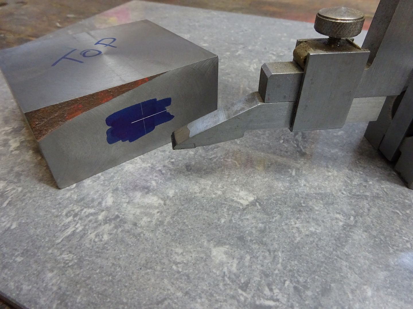
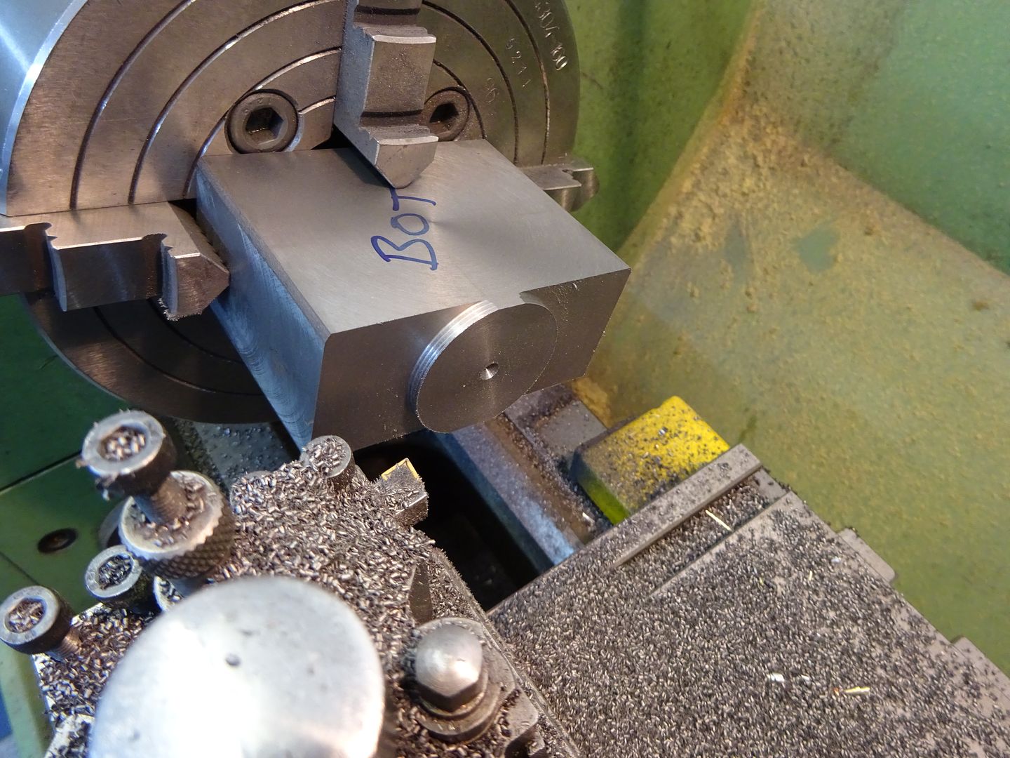
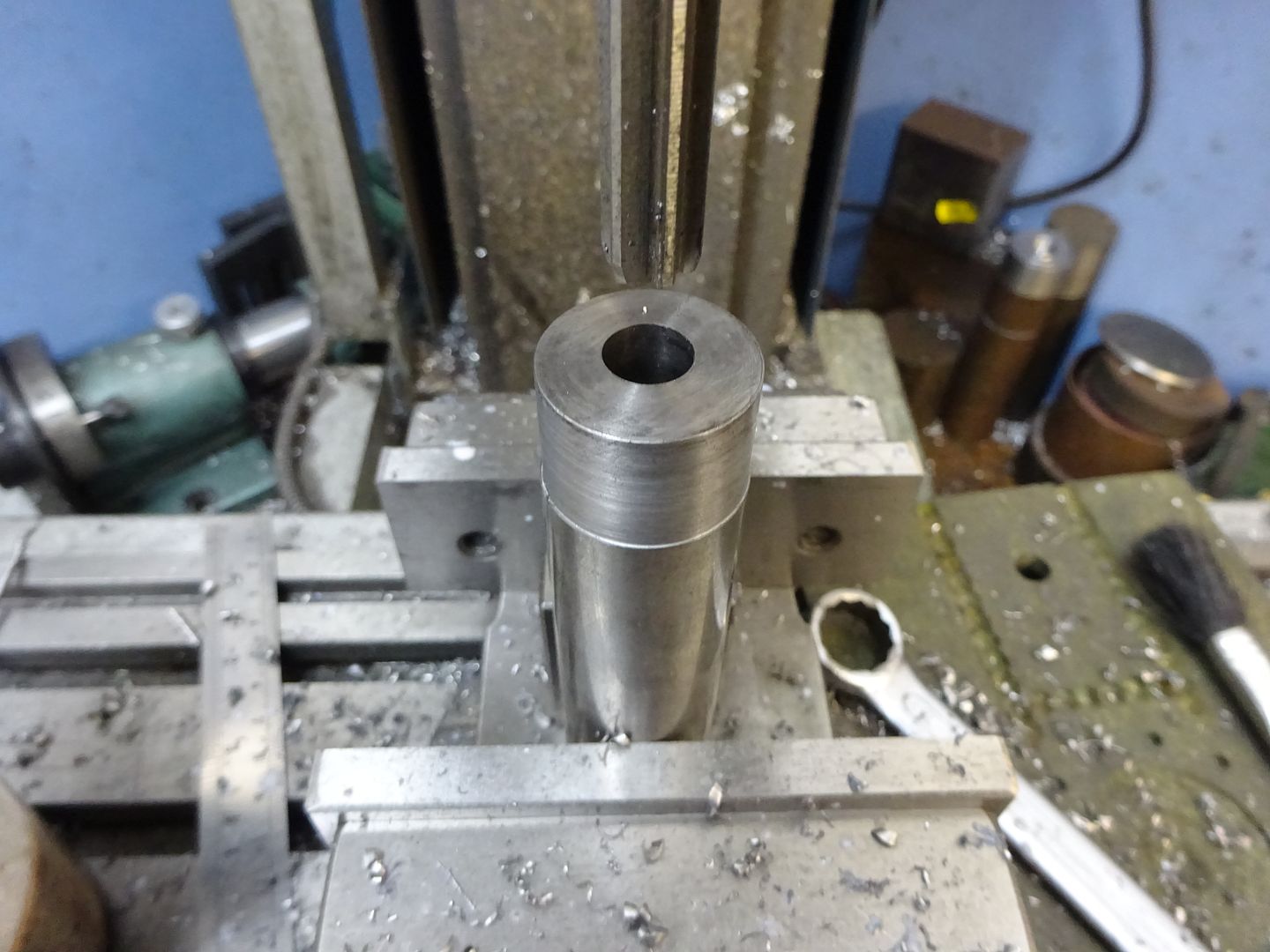
Mark the position of the bore in the middle of one end and punch.
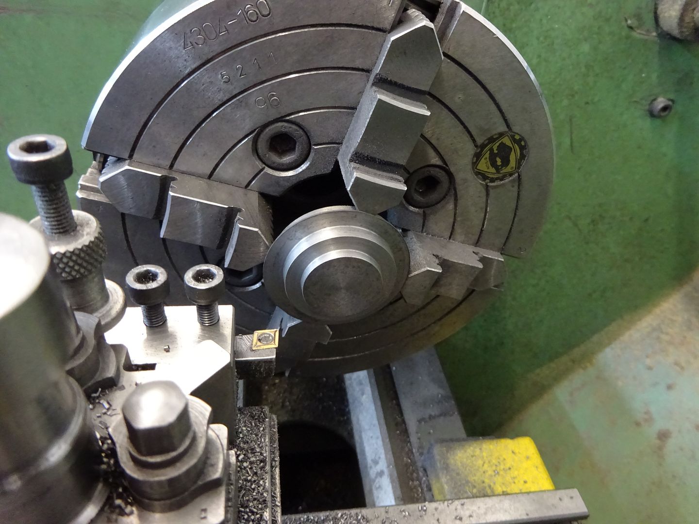
Back to the lathe and set the punch mark to run true in the 4-jaw using a sprung centre and dti
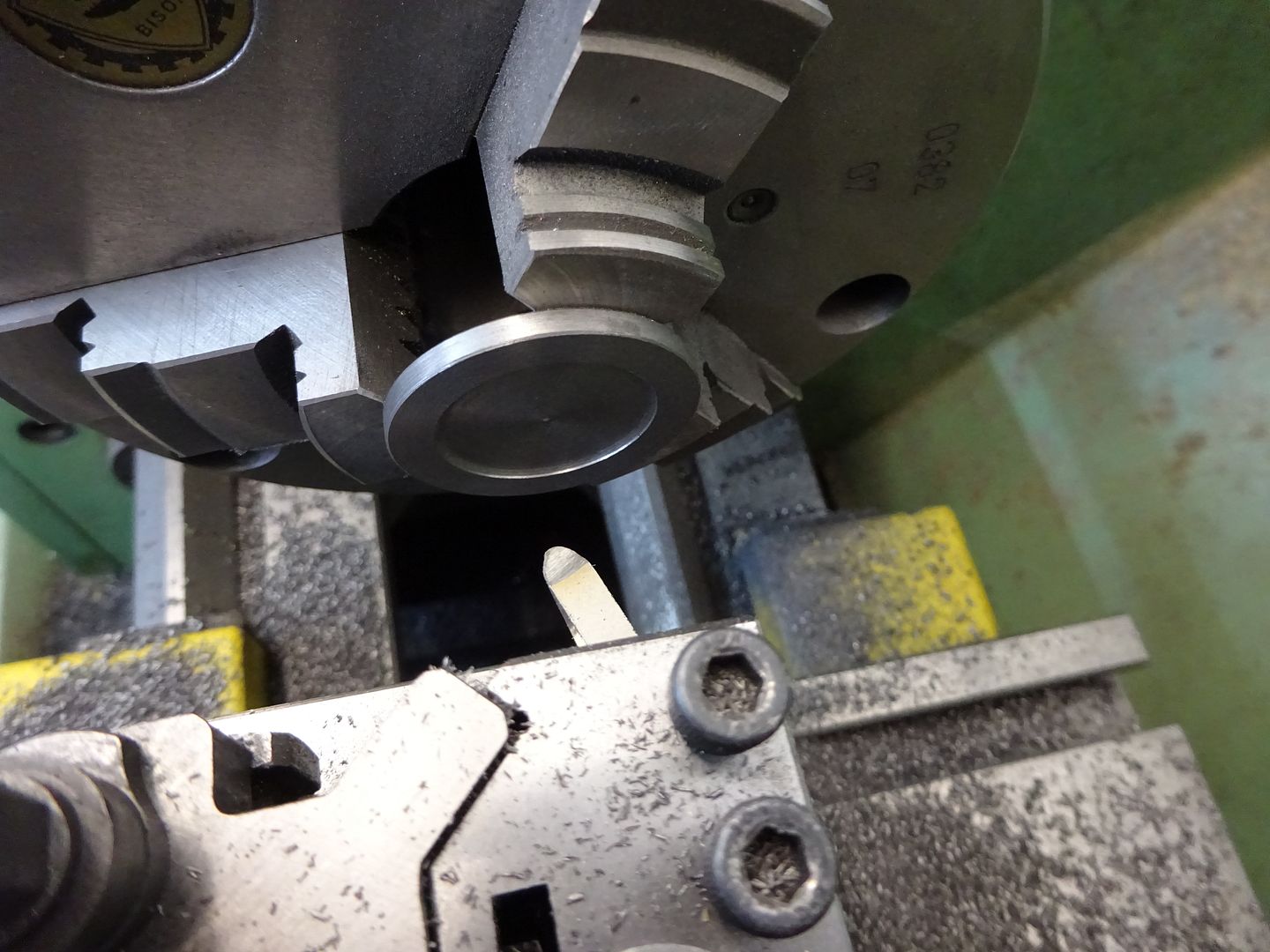
Using a standard right hand tool the spigot was roughed out
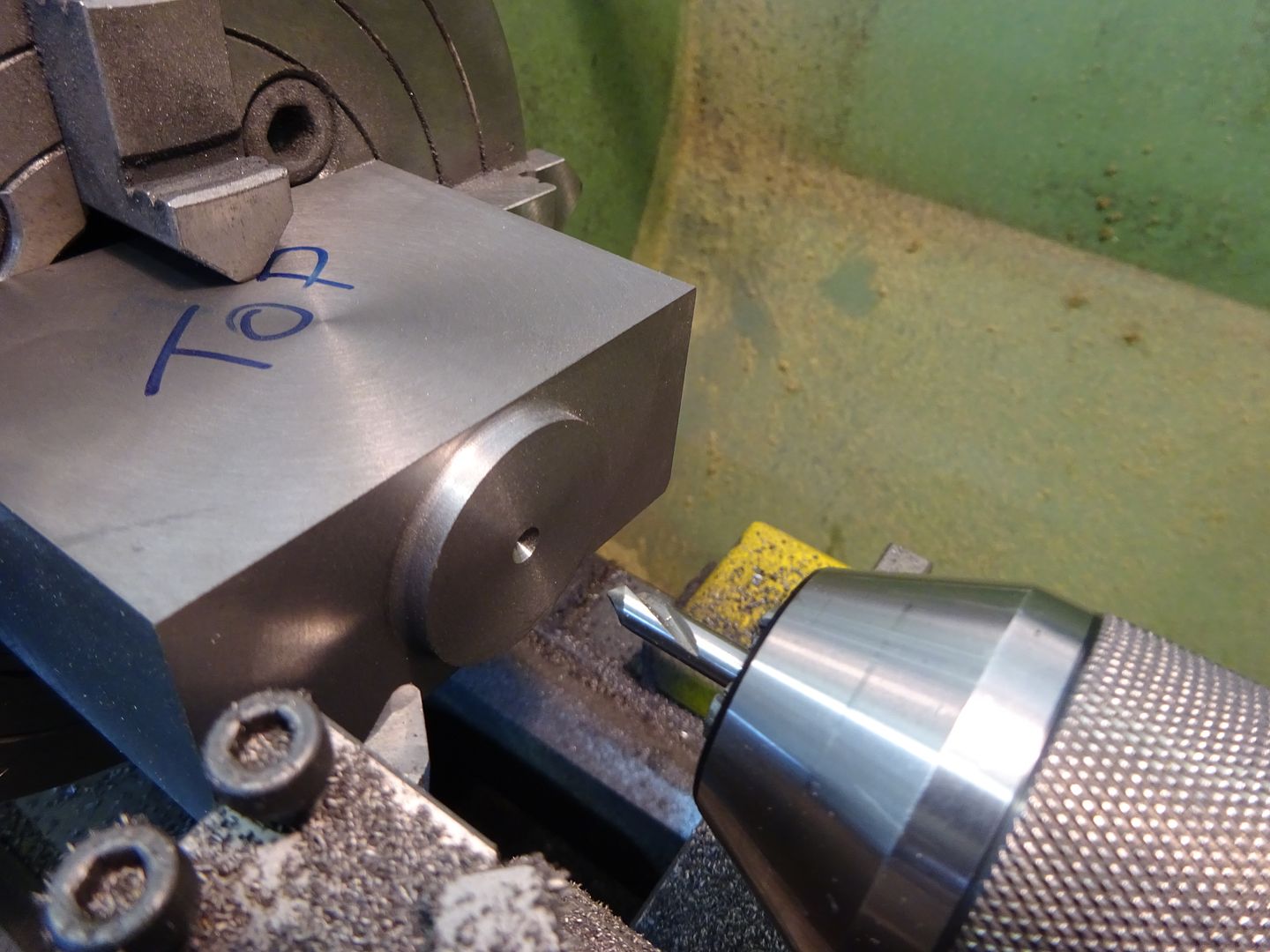
Then completed with a round nose tool to give the 1.5mm internal radius, the punch hole saw also enlarged with a spotting drill.
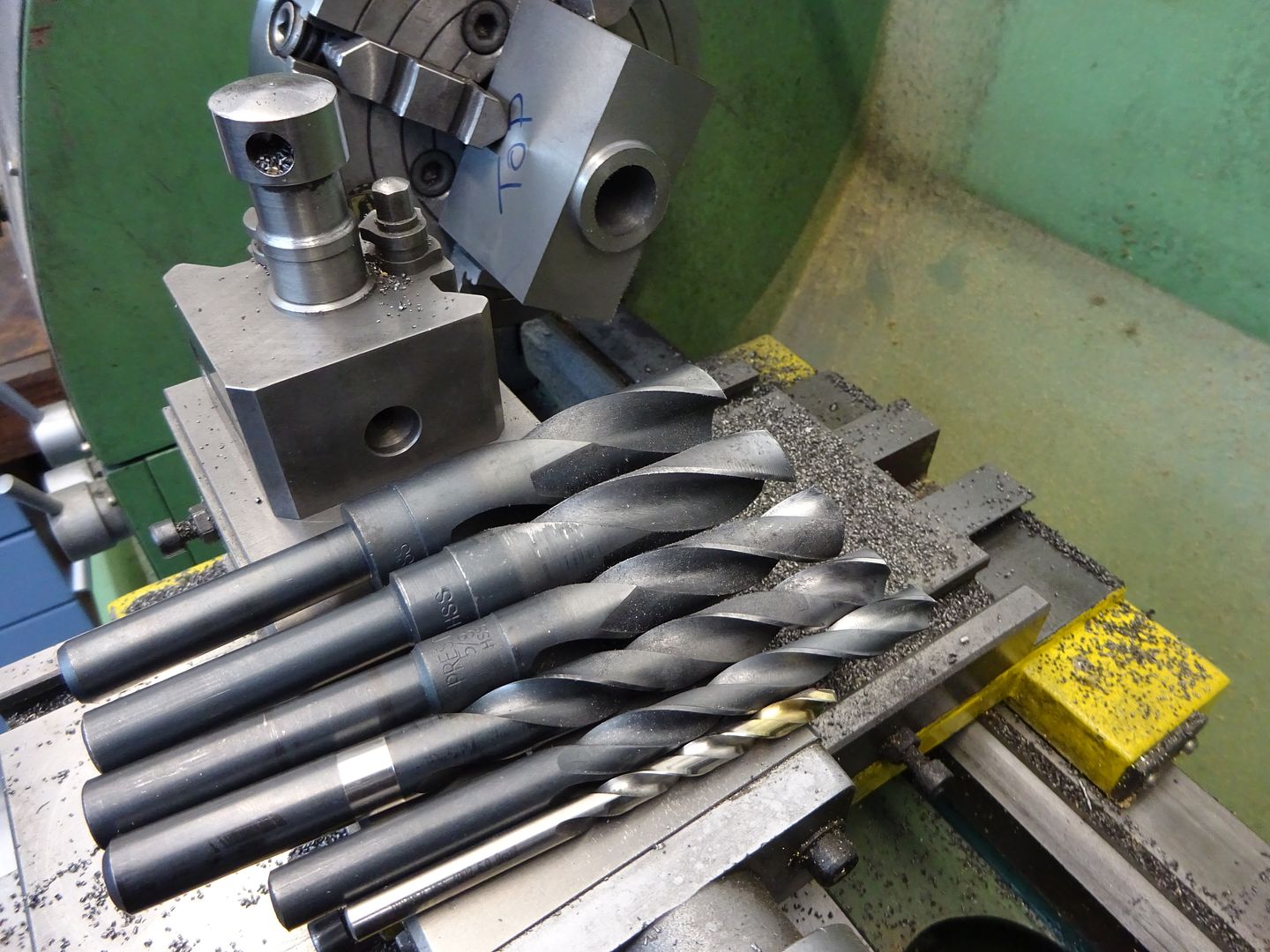
And then starting with a 6mm bit progressively opened up to 22mm with a range of drill bits.
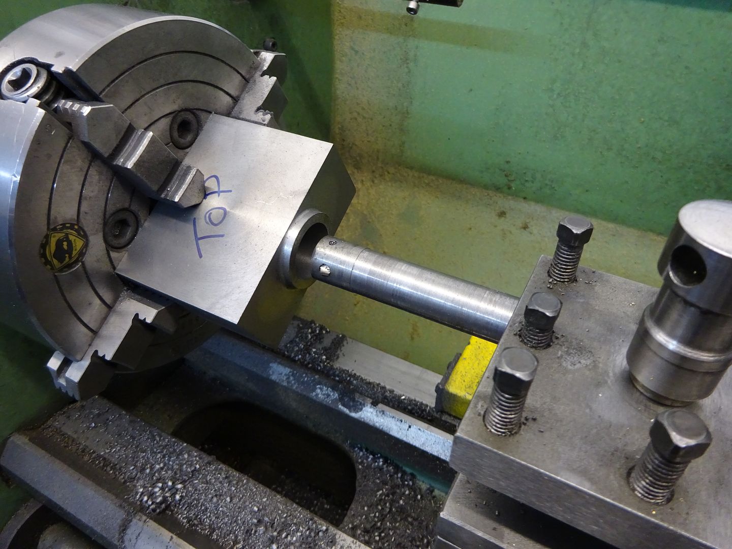
This allowed room for a sturdy boring bar to fit and take the bore out to the 24mm diameter finished size.
Then lightly chamfer the corner so the O rings don't get damaged when fitting the piston.
To be continued |
| JasonB | 01/03/2016 20:14:36 |
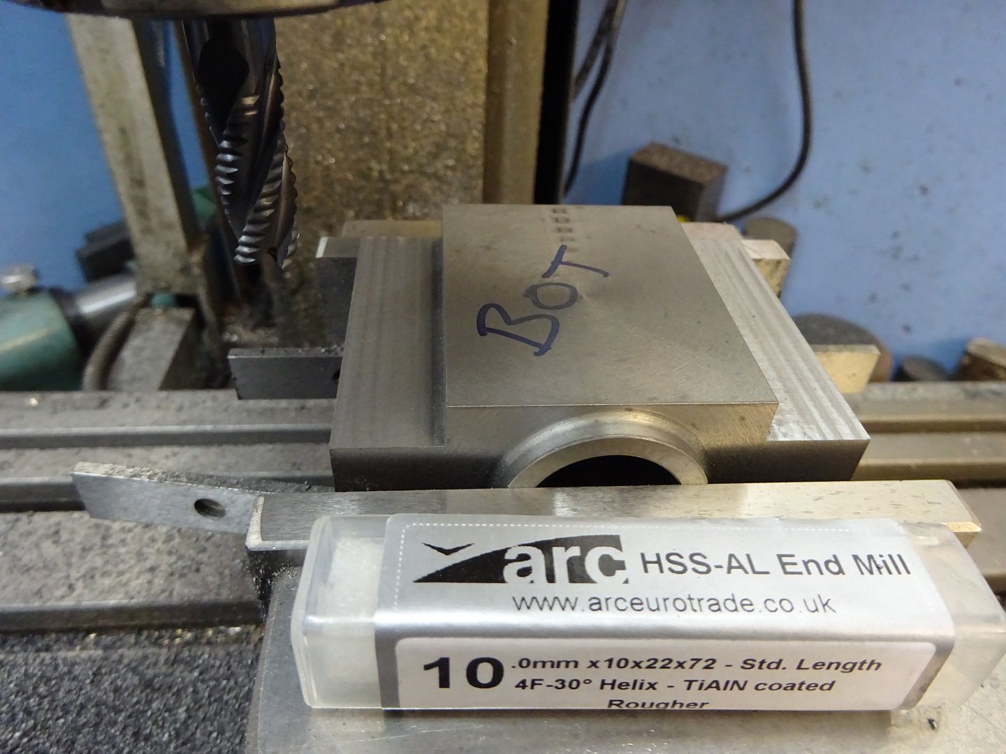
25215 forum posts 3105 photos 1 articles | Cylinder continued With the main bore in place next we can start to put some shape into the block. Starting with a newly purchased roughing mill from ARC the majority of the waste was removed 7.5mm tall and 3mm per pass.
And then with a 3-flute cutter finished to the required 8mm depth and 46mm width
Without disturbing the work the four M4 clearance holes for the hold down studs were added
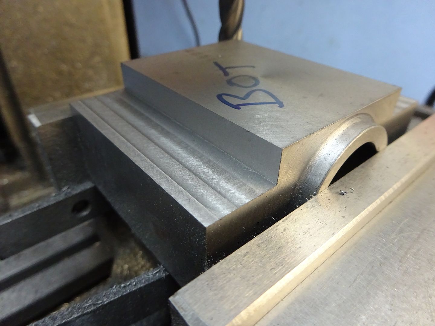
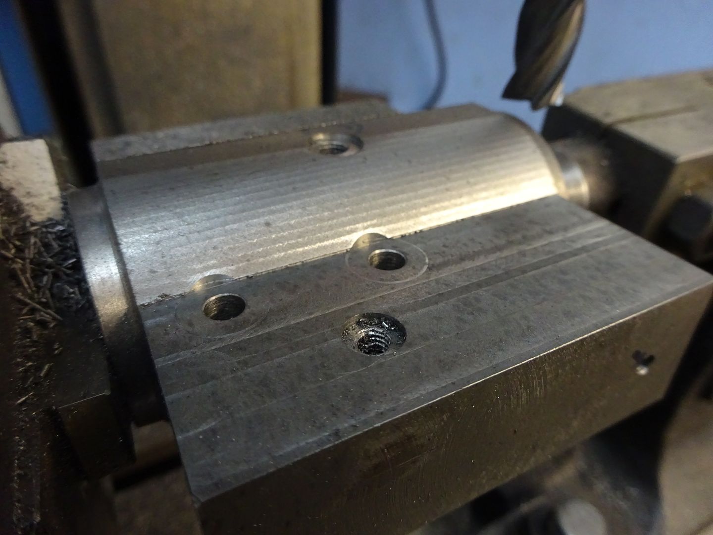
Now working from the top the two waste areas can be milled away as before and the holes for the oilers added. I counterbored the cylinder hold down holes but unless you are using large washers that is not actually needed.
The three tapped holes can then be counterbored 1mm deep for bosses like the bearing caps.
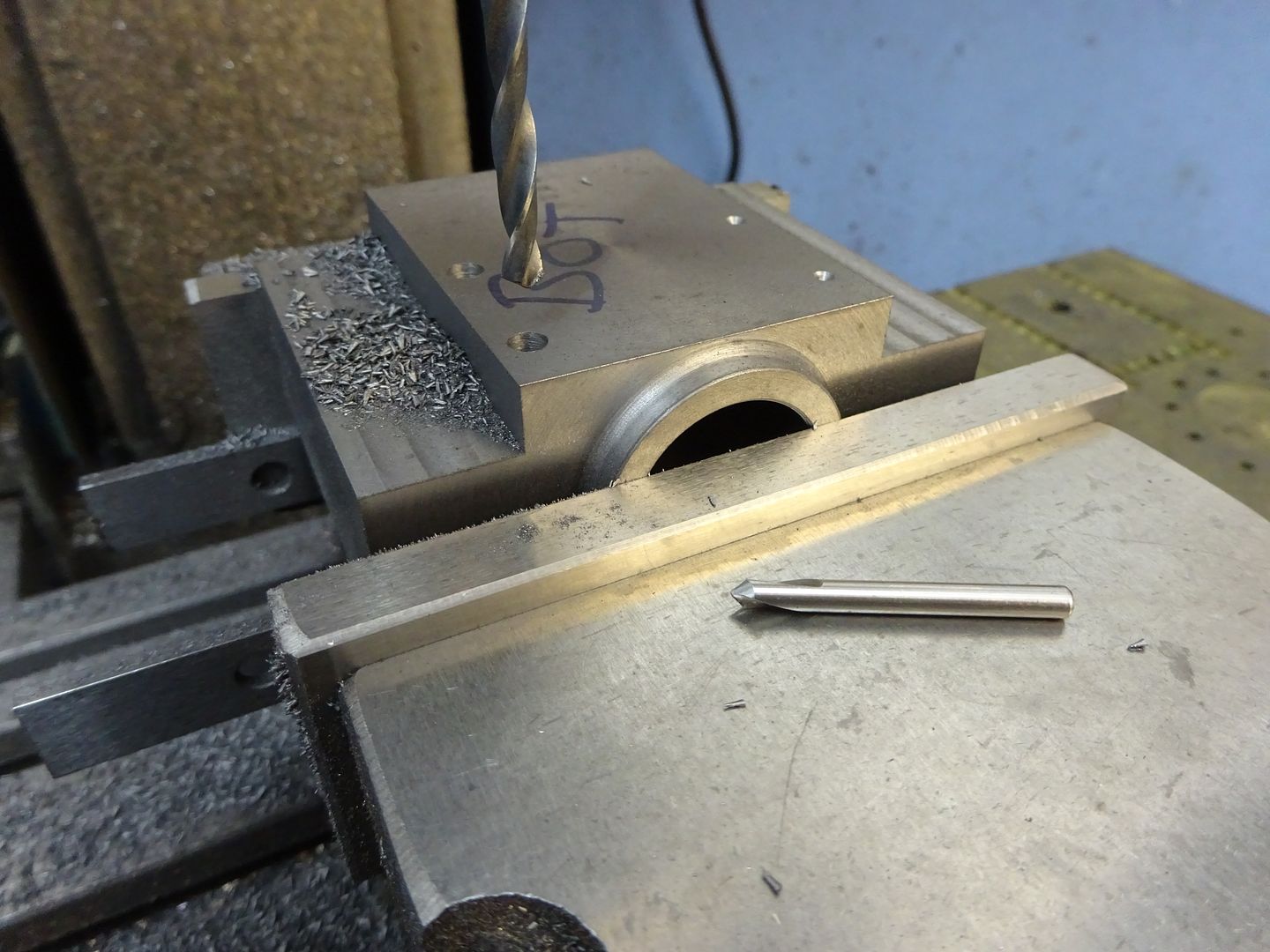
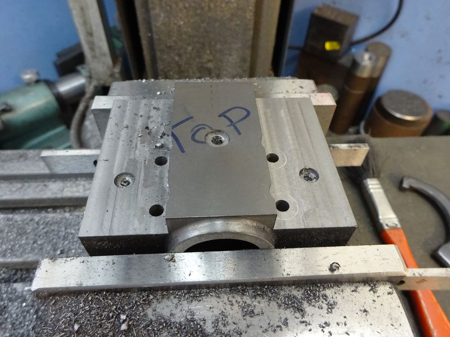
Next the back end of the cylinder can have the six cover holes drilled & tapped M2.5, note I have altered their position on the drawing which avoids a clash with the steam passages.
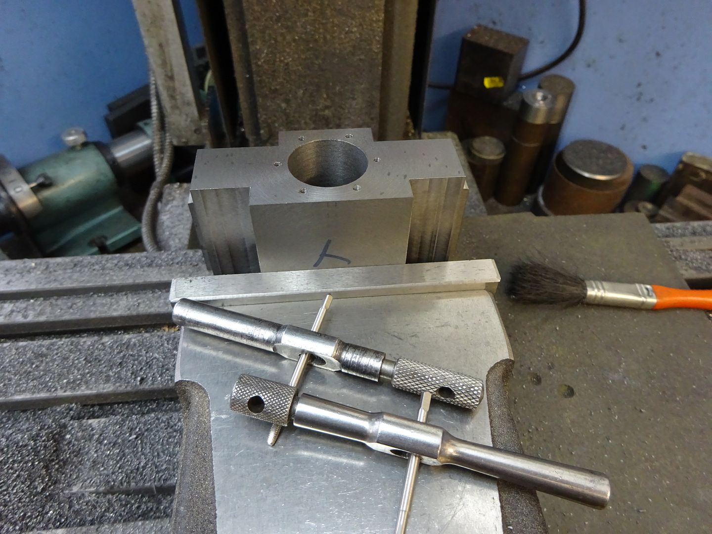
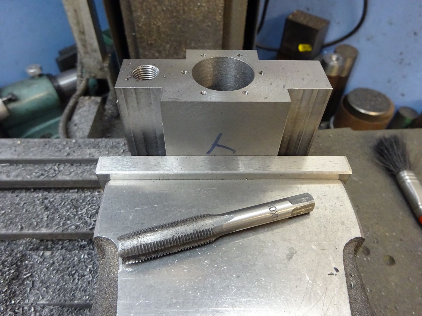
The inlet side is drilled 9mm x 16mm deep and tapped M10x1 followed by drilling and reaming 4mm the rest of the way through, a standard 4mm drill should just reach.
The exhaust side is again tapped M10x1 by 16mm deep then drilled 6mm for a further 16mm before reducing down to a reamed 4mm hole the rest of the way through, finally use a 8mm CSk bit to form the valve seating at the bottom of the M10 hole.
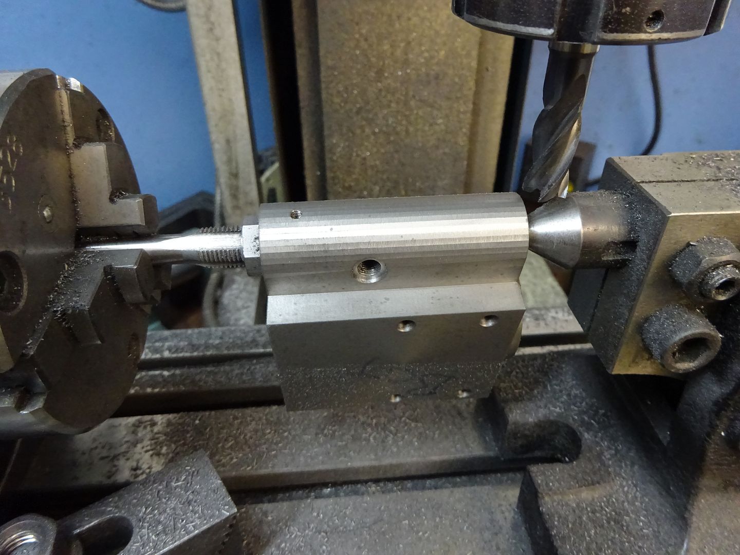
The two steam passages can be drilled 3.3mm into the cylinder bore and the outer part tapped M4 for plugs.
The last hole is the M6x0.75 exhaust port which is drille dup until it breaks into the 6mm hole and then counterbored 8mm x 1mm deep
You could stop at this stage
To be continued |
| JasonB | 01/03/2016 20:28:19 |
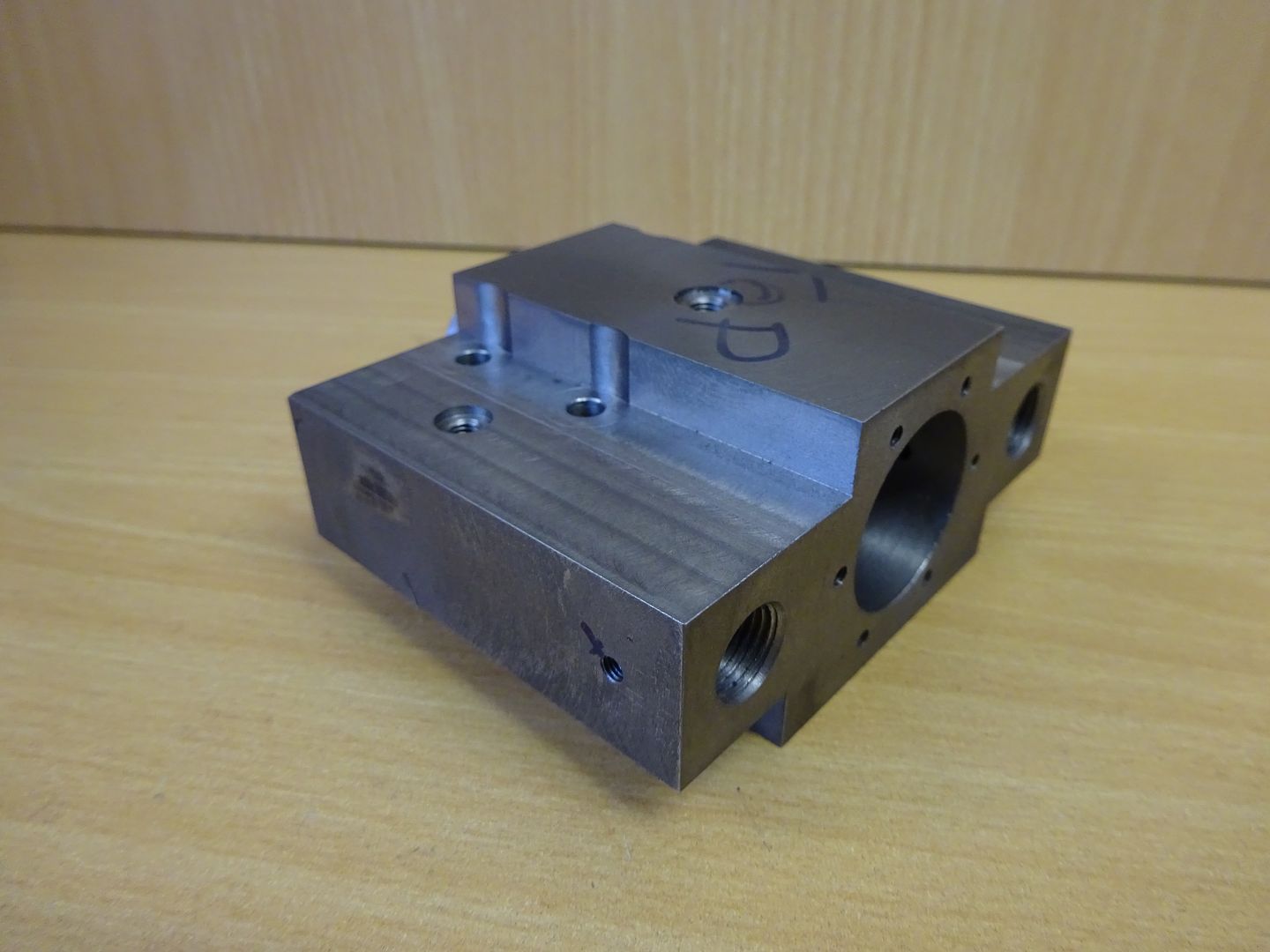
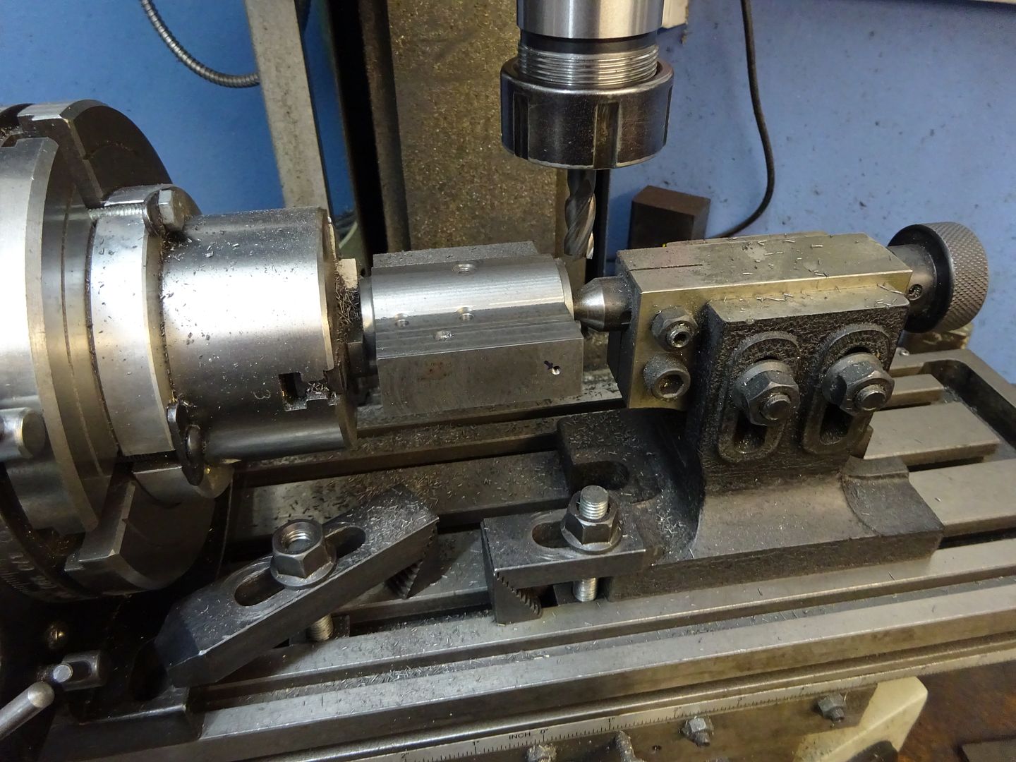
25215 forum posts 3105 photos 1 articles | Cylinder continued To round over the top of the cylinder I turned up a temporary plug so one end could be supported by the Rotary table tailstock and gripped the other end with the jaws expanded inside the bore. It was then just a case of taking a cut rotating 4 degrees (one turn of the handle) and then taking another pass.
The sides were done in a similar way, the tailstock in the 4mm hole and to hold the other end I made up a locknut so the M10x1 tap could be used as an arbor.
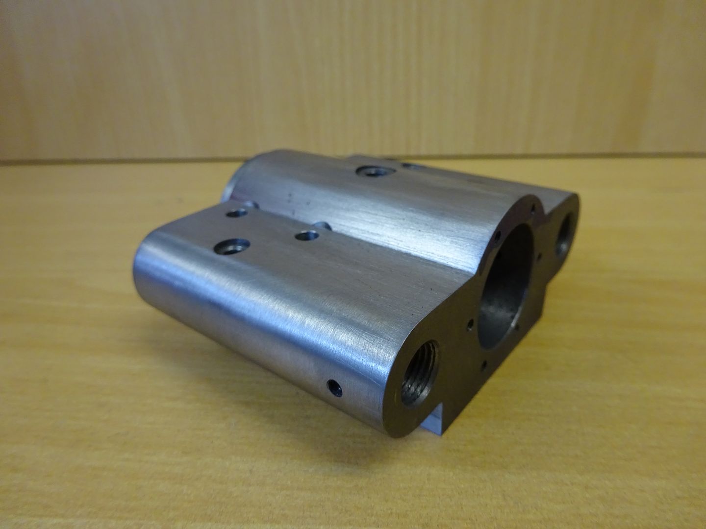
A bit of work with a file will soon blemd in the facetted cuts into a nice curve.
Finally the dummy bosses can b estck in with a dab of loctite
J Edited By JasonB on 03/03/2016 16:01:08 |
| Emgee | 03/03/2016 15:28:01 |
| 2610 forum posts 312 photos | Hi Jason, can you check the Dropbox message. Emgee |
| JasonB | 03/03/2016 16:04:07 |
25215 forum posts 3105 photos 1 articles | Message or link? I have reposted the link just incase there is a problem, sometimes does not open well on IE but OK on Chrome |
| JasonB | 03/03/2016 16:18:19 |
25215 forum posts 3105 photos 1 articles | Ah got the message. Download the file from dropbox and save it on your harddisk then open it from the hadrdisk not via the Dropbox site. You will also need to trust the document. Also needs flash so may not work on ipad etc This is about the 3D pdf of the assembled engine, if you want to be able to move around it and zoom in etc that is how to do it from Dropbox Edited By JasonB on 03/03/2016 16:22:14 |
| Emgee | 03/03/2016 17:53:43 |
| 2610 forum posts 312 photos | OK Jason, did as suggested and "activate" was there so could move the model around. Emgee |
| JasonB | 13/03/2016 20:18:12 |
25215 forum posts 3105 photos 1 articles | Cylinder End Cover This is quite a simple piece after the cylinder, I used a stub end of cast iron bar but steel would do. Turn down to 30mm dia and then turn the 24mm dia x 3mm long spigot and part/saw off
Now holding by the spigot face off to 3mm thick and decorate as desired, I went for a simple 20mm dia recess with a rounded edge. The original CME engine carried the CME logo here.
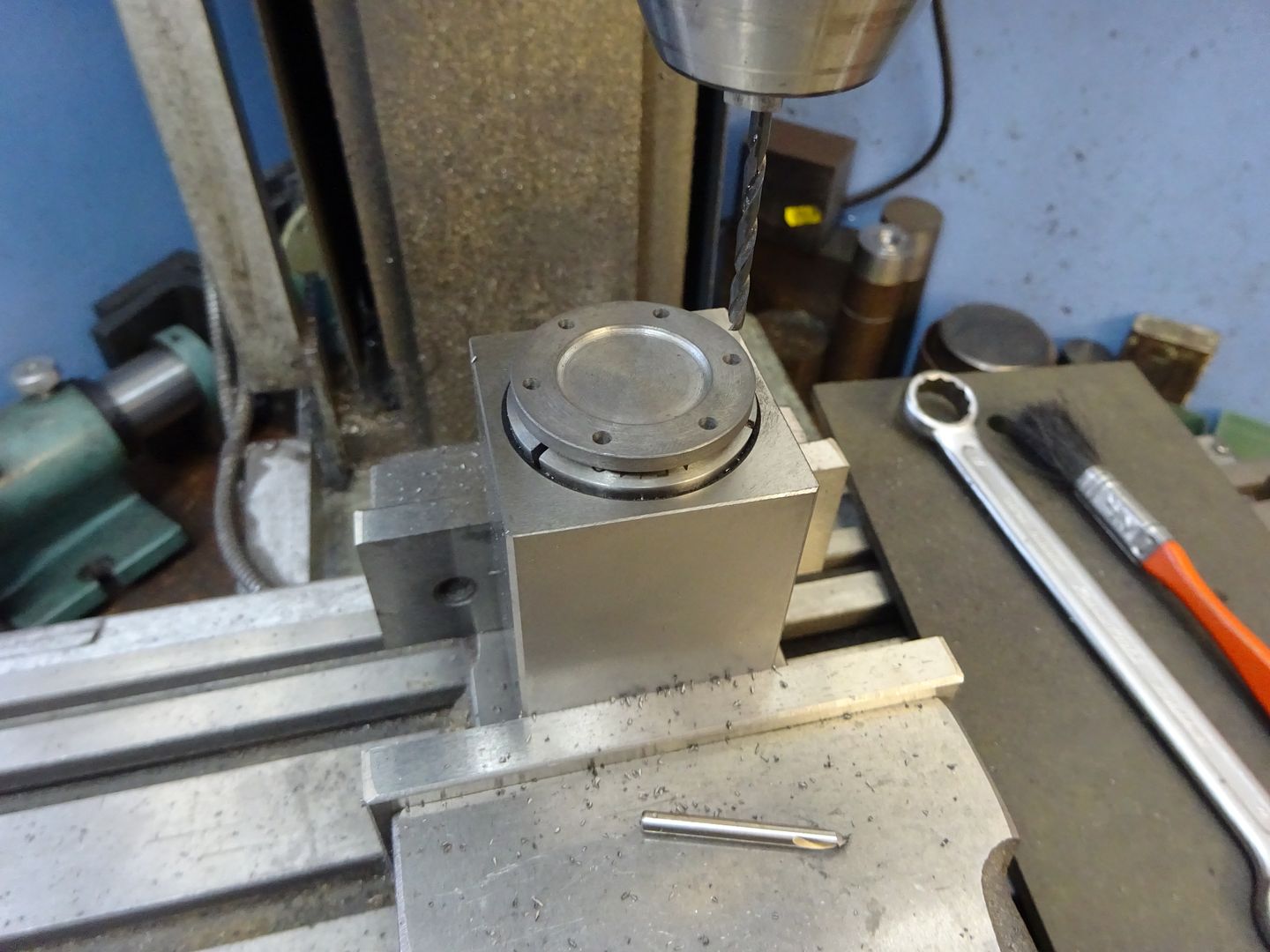
Now over to the mill to drill the six M2.5 clearance holes on a 30mmPCD and thats the cover finished.
I turned down a piece of 1" bar to 24mm long enough for two eccentrics, parting cuts and a little to clean up afterwards then set the bar in the mill vice, indicate the middle then move 1mm to the back and drill and ream out to 10mm dia. It could also be done in the 4-jaw but I could not be bothered to change it over.
You can then part off two slices and finish to 6mm thick, drill and tap for a M3 grub screw in each. J Edited By JasonB on 14/03/2016 20:26:34 |
| JasonB | 14/03/2016 20:31:25 |
25215 forum posts 3105 photos 1 articles | Thanks to Marcus for pointing out I had put the main bearings onto two drawings, sheet No 6 has now been revised and the link at the end of the last post will take you to it. Good to know someone is reading the thread |
| JasonB | 17/03/2016 19:30:00 |
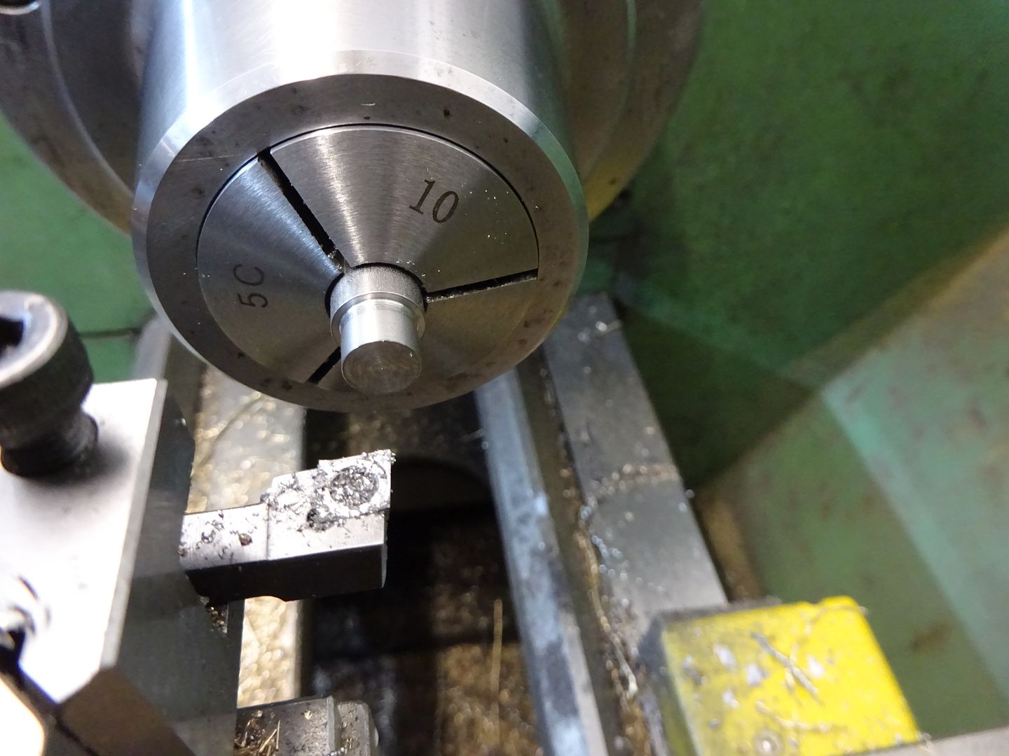
25215 forum posts 3105 photos 1 articles | Crankshaft I had intended to make this from 10mm PGMS (Precision Ground Mild Steel) which is what I have spec'd on the drawing but could not pick up any at the time I wanted it and postage on one bit of metal would have been high so I opted for some 10mm Stainless steel which I already had, either would do the job. The main shaft can be turned down to 112mm long which is right for the two Perseus flywheels that I used. If you buy different flywheel castings or want to add a pully then you may need a longer length. The pin can be faced off to give the required 22mm overall length then reduced at both ends to 8mm dia for a length of 6mm
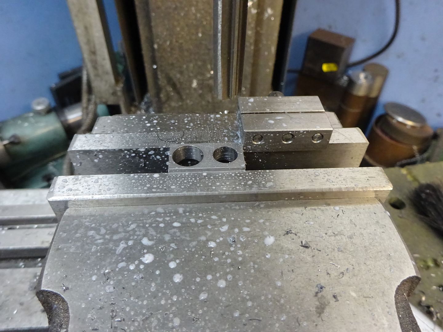
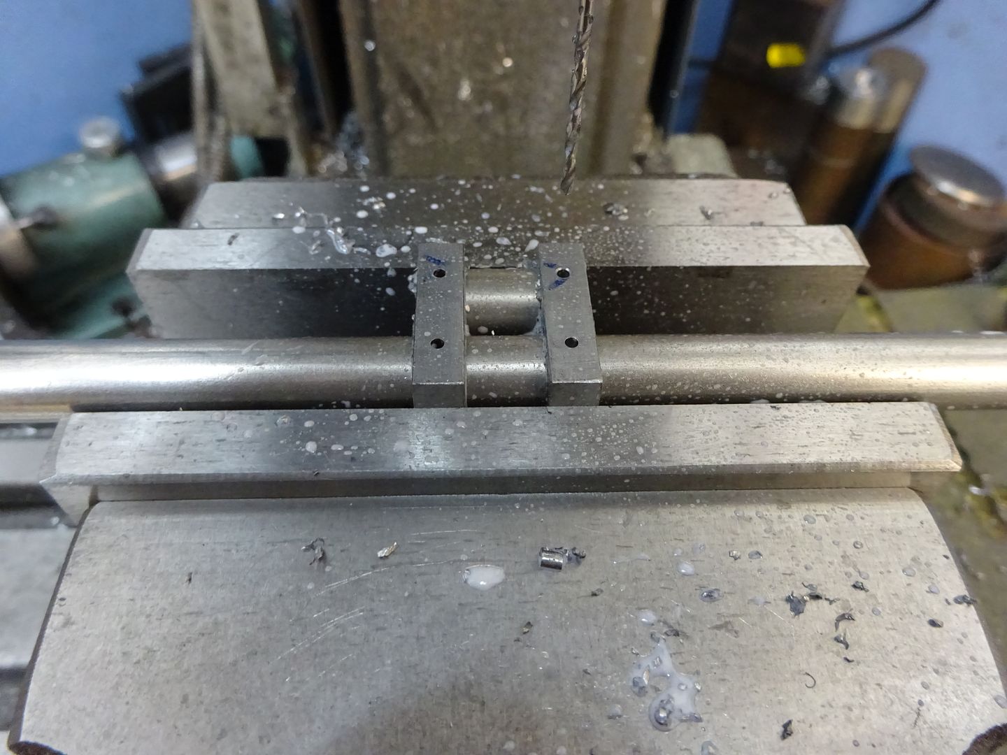
Machine up two pieces of mild steel 12x6x24mm and then holding them in the vice drill and then ream the 10mm and 8mm holes. If you use a vice stop it saves having to locate the edge of the second web.
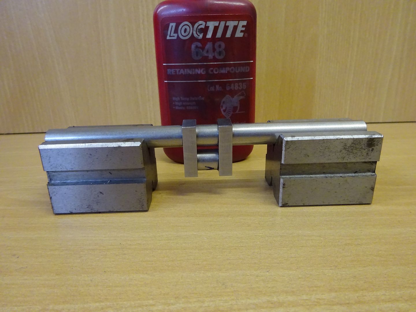
Clean up all the parts with solvent so the loctite will make a good bond and then start assembly. I did it in two stages, firstly stick the pin into the webs using the shaft to keep things lined up. Then when that has set the pin/webs can be bonded to the main shaft, I supported them in a couple of Vee blocks while things dried.
I'm more used to silver soldering crankshafts or cutting from solid so decided to pin the joints for good measure. Drill 1.5mm cross holes and lightly countersink.
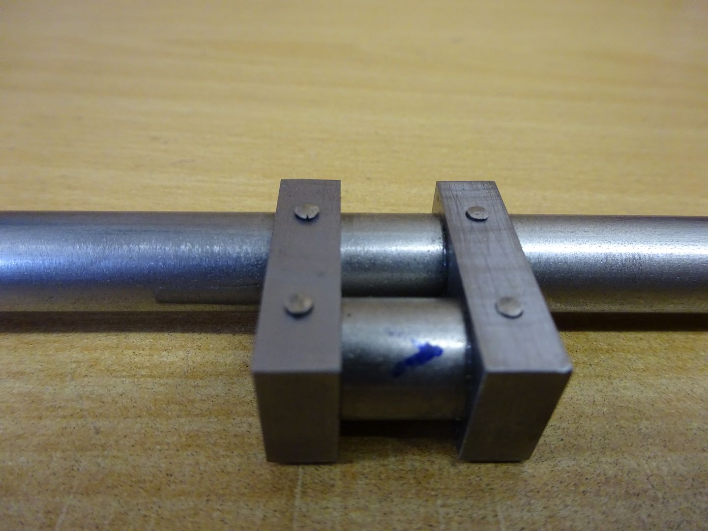
Then push some 1.5mm steel rod through the holes and pein over the ends with a hammer.
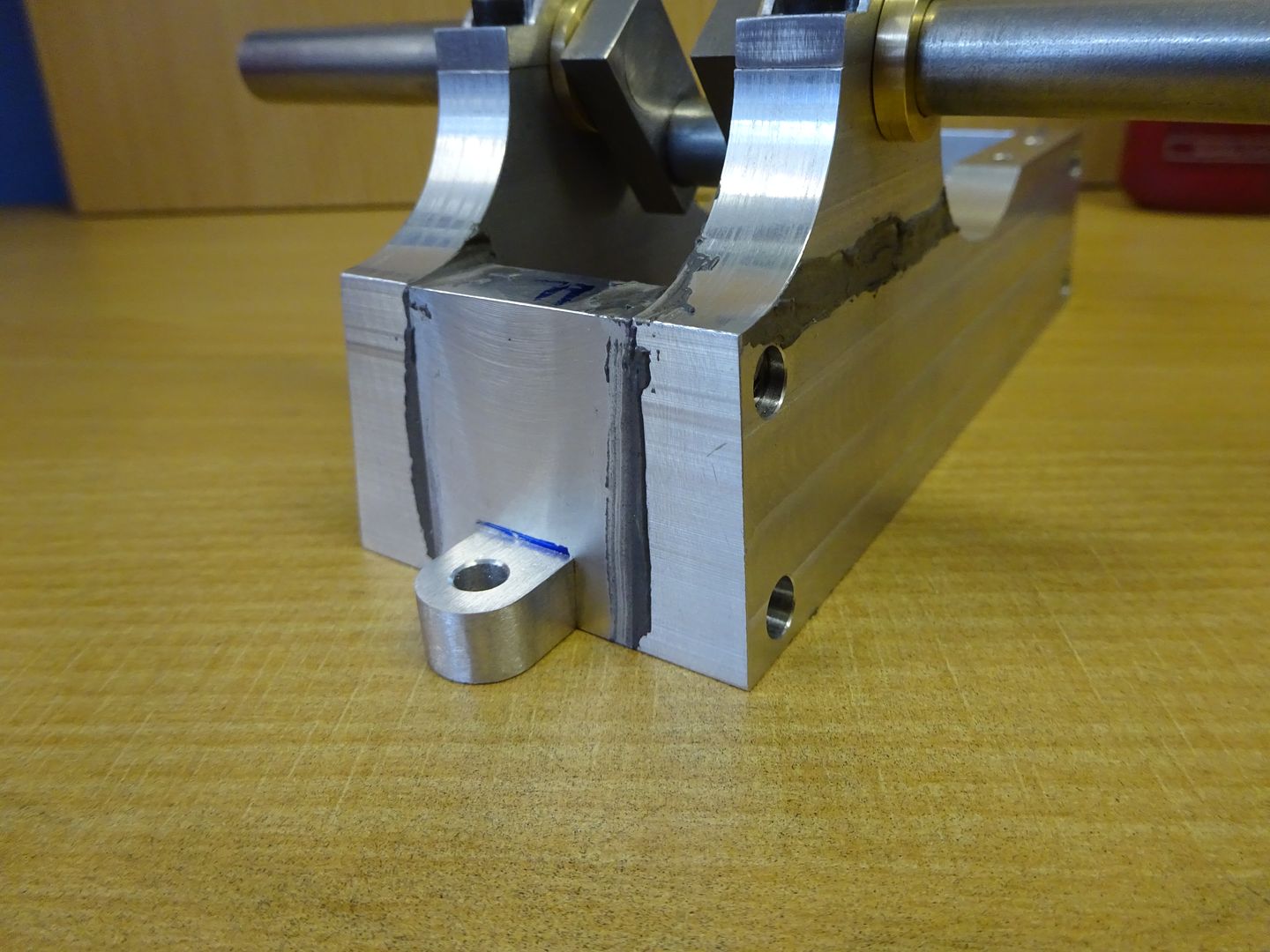
All that remains is to cut out the middle of the shaft that is not needed and file the ends flush with the insides of the webs, the ends of the pins can also be filed down at the same time. Check that the crankshaft turns smoothly in the bearings and make any adjustments that may be needed as its easier to do it at this stage. Once happy that everything turns freely the base can be joined together. I used a small amount of JBWeld spread over the 4 joints and then screwed the parts together on a flat surface making sure that the crankshaft turned as the screws were nipped up.
If you leave the feet off it is easy to clean up across the whole end to remove excess filler and any high spots if the parts don't quite all lay flush. Once that is done the feet can be stuck in the same way. I prefer to use an easier to sand filler for cosmetic filling so some U-Pol car body filler was used to fill the screw holes. The same filler can be used to add a fillet around the feet and oiler bosses. J |
| Chris Evans 6 | 18/03/2016 09:51:04 |
 2156 forum posts | Jason, I am not a model maker as pre war motorcycles are my main interest but reading such a common sense clear build log as yours I am tempted to make one. What I like is the lack of chasing accuracy beyond what is required to make it work. When my work load gets down a bit I will make a start. Chris. |


Please login to post a reply.
Magazine Locator
Want the latest issue of Model Engineer or Model Engineers' Workshop? Use our magazine locator links to find your nearest stockist!
Sign up to our Newsletter
Sign up to our newsletter and get a free digital issue.
You can unsubscribe at anytime. View our privacy policy at www.mortons.co.uk/privacy
Latest Forum Posts
- *Oct 2023: FORUM MIGRATION TIMELINE*
05/10/2023 07:57:11 - Making ER11 collet chuck
05/10/2023 07:56:24 - What did you do today? 2023
05/10/2023 07:25:01 - Orrery
05/10/2023 06:00:41 - Wera hand-tools
05/10/2023 05:47:07 - New member
05/10/2023 04:40:11 - Problems with external pot on at1 vfd
05/10/2023 00:06:32 - Drain plug
04/10/2023 23:36:17 - digi phase converter for 10 machines.....
04/10/2023 23:13:48 - Winter Storage Of Locomotives
04/10/2023 21:02:11 - More Latest Posts...
- View All Topics
Support Our Partners


Shopping Partners
Subscription Offer

Latest "For Sale" Ads
- Reeves** - Rebuilt Royal Scot by Martin Evans
by John Broughton
£300.00 - BRITANNIA 5" GAUGE James Perrier
by Jon Seabright 1
£2,500.00 - Drill Grinder - for restoration
by Nigel Graham 2
£0.00 - WARCO WM18 MILLING MACHINE
by Alex Chudley
£1,200.00 - MYFORD SUPER 7 LATHE
by Alex Chudley
£2,000.00 - More "For Sale" Ads...
Latest "Wanted" Ads
- D1-3 backplate
by Michael Horley
Price Not Specified - fixed steady for a Colchester bantam mark1 800
by George Jervis
Price Not Specified - lbsc pansy
by JACK SIDEBOTHAM
Price Not Specified - Pratt Burnerd multifit chuck key.
by Tim Riome
Price Not Specified - BANDSAW BLADE WELDER
by HUGH
Price Not Specified - More "Wanted" Ads...
Get In Touch!
Do you want to contact the Model Engineer and Model Engineers' Workshop team?
You can contact us by phone, mail or email about the magazines including becoming a contributor, submitting reader's letters or making queries about articles. You can also get in touch about this website, advertising or other general issues.
Click THIS LINK for full contact details.
For subscription issues please see THIS LINK.
Digital Back Issues


Donate

 Register
 Log-in
Model Engineer Magazine
- Percival Marshall
- M.E. History
- LittleLEC
- M.E. Clock

ME Workshop
- An Adcock
- & Shipley
- Horizontal
- Mill

Subscribe Now
- Great savings
- Delivered to your door

Pre-order your copy!
- Delivered to your doorstep!
- Free UK delivery!
All Forum Topics > Work In Progress and completed items > Jowitt MkII Popett Valve Engine Build