Forum sponsored by:

ML7 Lath carriage assembly
Feedscrew
| Salij H | 30/04/2015 21:49:16 |
| 7 forum posts 2 photos | the feedscrew of the carriage ass.on my ML7 lath has an adjustable scale.But when I turn the feedscrew the scale sometimes don't move sothat it is unreliable to use. Who can give me a solution or has a drawing to see the working. |
| Tim Stevens | 01/05/2015 15:29:32 |
 1779 forum posts 1 photos | There are three 'feedscrews' on a standard ML7. The long one under the edge of the apron, running the length of the machine, doesn't have a scale as standard, but there is an extra calibrated round handle at the tailstock end. The other two are on the cross slide for the toolpost, and on the toolpost slide itself. Both have a standard bevel scale, but fixed. So, it may be that your ML7 has been modified over the years, and it is certain that an adjustable scale is a useful mod to have. So, can you tell us a bit more about the position etc of your problem scale, please? The normal scheme for an adjustable scale is to have a spring holding the disc with the calibrations against a disc fixed to the spindle. Friction moves them together, but allows the scale to be zeroed so you can return to a given setting easily. If you take one of them apart, do it inside a polythene bag, and then you won't spend three days looking for the spring... Regards Tim |
| Salij H | 03/05/2015 10:08:41 |
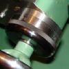
| 7 forum posts 2 photos | Thanks for your email. Enclosed I am sending you a picture from the toolpost
Separate on that toolpost you see the original bevel scale which gave the problem that it did not move when I turned the feedscrew.
I made a bigger one sothat it was easier to read the scale. But still I have the problem that it does not always adjust.
On the front of that bevel scale (or do they call it micrometer dial?) you see part of the fixing nut which is between the scale and the feedscrew handle. I call it fixing nut, but is a round female threaded bush with a flat part on front that goes into the bevel scale. You see on the separate scale the round hole for that.
Do you mean with spring holding disc that this has to be put between that fixing nut and the bevel scale.
On the back site of the bevelscale there is a fibre washer.
|
| Steamer1915 | 03/05/2015 19:05:05 |
 171 forum posts 42 photos | Salij, Is this the kind of screw you have? Best regards, Steve. |
| Michael Gilligan | 03/05/2015 19:25:53 |
 23121 forum posts 1360 photos | Posted by Steamer1915 on 03/05/2015 19:05:05:
Salij, Is this the kind of screw you have? . Steve, I do hope that Salij has the straight version [not like that one of mine] MichaelG. |
| Steamer1915 | 03/05/2015 19:37:16 |
171 forum posts 42 photos | Yes Michael, Should have given you the credit. Apologies.
Steve. |
| Michael Gilligan | 03/05/2015 19:47:46 |
23121 forum posts 1360 photos | No problem at all, Steve MichaelG. |
| Salij H | 03/05/2015 21:21:13 |
| 7 forum posts 2 photos | This is the one I have. The original scale is left separate. I made a some what bigger one which is easier to read. Henk Salij |
| speelwerk | 03/05/2015 22:02:36 |
| 464 forum posts 2 photos | Henk, to place a photo in a post you first have to upload it to your album. Henk sounds very Dutch so I give it a try; een foto plaatsen in een bericht gaat een beetje omslachtig, je moet dat eerst in je fotoalbum (vind je helemaal bovenaan op deze pagina) hoogladen en daarna kan je die foto pas in je bericht zetten. Niko. |
| Salij H | 03/05/2015 22:22:50 |
| 7 forum posts 2 photos |
|
| Michael Gilligan | 03/05/2015 22:27:51 |
23121 forum posts 1360 photos | Posted by Salij H on 03/05/2015 22:22:50:
Indeed I am dutch and live in Ridderkerk in the Netherlands. So I put the picture in my album. Is it now visible. Henk Salij . Perfectly visible ... Thanks to Niko's quick thinking; and communication at the speed of light ! MichaelG. |
| Salij H | 03/05/2015 22:36:54 |
| 7 forum posts 2 photos | Thanks for this fast reply. I did not know I had to place the picture in an album because it is the first time that I make use of this forum inspite that I have since very long the MEW Henk |
| Tim Stevens | 03/05/2015 23:22:23 |
1779 forum posts 1 photos | Sorry, but I can't open your picture. Tim |
| speelwerk | 03/05/2015 23:29:26 |
| 464 forum posts 2 photos | The problem is that original this Myford had a fixed dail as in the picture of Steve (or is it MichaelG?), the one you replaced is also not original. Perhaps you can get it working correctly with a bit of tinkering, if not you are most likely best of by buying from Myford UK a "C13, Resettable Dail - Metric 20/253". I myself have no experience with this up-date so do not know if they have the same problem, perhaps other forum members can comment on them. Niko. Edited By speelwerk on 03/05/2015 23:32:32 |
| Michael Gilligan | 03/05/2015 23:58:41 |
23121 forum posts 1360 photos | Posted by Tim Stevens on 03/05/2015 23:22:23:
Sorry, but I can't open your picture. . Tim, Try refreshing the page ... you may be seeing a cached version of the post. MichaelG. |
| Enough! | 04/05/2015 01:20:37 |
| 1719 forum posts 1 photos | Henk, the dials on your machine are not original. They look like replacements taken from one of the Far Eastern lathes or mills which are available as spare-parts from some dealers. However, in that case they should consist of a concentric assembly .... an inner hub and the outer, calibrated ring with a "leaf" spring to provide friction between ..... and it doesn't look as if your are like that - but it's hard to tell. Yours seem to be replacement, fixed dials (like the original) but which are not fixed very well so that they slip. If that is true ... well the originals were horrible and the replacements won't be much better. Resettable dials are much to be preferred and can be made from scratch or (as I did) they can be fairly easily adapted from the lathe/mill spare parts referred to before.
|
| Salij H | 04/05/2015 07:32:06 |
| 7 forum posts 2 photos | Thank you all for your fast contribution. It gave me a lot of thinking and I am going to try some solutions like more friction. |
| daveb | 04/05/2015 12:25:57 |
| 631 forum posts 14 photos | Drill from the edge to the centre, M3 or 4, tap thread, insert brass pad coil spring and grub screw, adjust for desired friction. |
| Salij H | 04/05/2015 13:46:45 |
| 7 forum posts 2 photos | That is a brilliant solution. Thanks for this. I did it immediately and it works! Henk.
|


Please login to post a reply.
Magazine Locator
Want the latest issue of Model Engineer or Model Engineers' Workshop? Use our magazine locator links to find your nearest stockist!
Sign up to our Newsletter
Sign up to our newsletter and get a free digital issue.
You can unsubscribe at anytime. View our privacy policy at www.mortons.co.uk/privacy
Latest Forum Posts
- *Oct 2023: FORUM MIGRATION TIMELINE*
05/10/2023 07:57:11 - Making ER11 collet chuck
05/10/2023 07:56:24 - What did you do today? 2023
05/10/2023 07:25:01 - Orrery
05/10/2023 06:00:41 - Wera hand-tools
05/10/2023 05:47:07 - New member
05/10/2023 04:40:11 - Problems with external pot on at1 vfd
05/10/2023 00:06:32 - Drain plug
04/10/2023 23:36:17 - digi phase converter for 10 machines.....
04/10/2023 23:13:48 - Winter Storage Of Locomotives
04/10/2023 21:02:11 - More Latest Posts...
- View All Topics
Support Our Partners


Shopping Partners
Subscription Offer

Latest "For Sale" Ads
- Reeves** - Rebuilt Royal Scot by Martin Evans
by John Broughton
£300.00 - BRITANNIA 5" GAUGE James Perrier
by Jon Seabright 1
£2,500.00 - Drill Grinder - for restoration
by Nigel Graham 2
£0.00 - WARCO WM18 MILLING MACHINE
by Alex Chudley
£1,200.00 - MYFORD SUPER 7 LATHE
by Alex Chudley
£2,000.00 - More "For Sale" Ads...
Latest "Wanted" Ads
- D1-3 backplate
by Michael Horley
Price Not Specified - fixed steady for a Colchester bantam mark1 800
by George Jervis
Price Not Specified - lbsc pansy
by JACK SIDEBOTHAM
Price Not Specified - Pratt Burnerd multifit chuck key.
by Tim Riome
Price Not Specified - BANDSAW BLADE WELDER
by HUGH
Price Not Specified - More "Wanted" Ads...
Get In Touch!
Do you want to contact the Model Engineer and Model Engineers' Workshop team?
You can contact us by phone, mail or email about the magazines including becoming a contributor, submitting reader's letters or making queries about articles. You can also get in touch about this website, advertising or other general issues.
Click THIS LINK for full contact details.
For subscription issues please see THIS LINK.
Digital Back Issues


Donate

 Register
 Log-in
Model Engineer Magazine
- Percival Marshall
- M.E. History
- LittleLEC
- M.E. Clock

ME Workshop
- An Adcock
- & Shipley
- Horizontal
- Mill

Subscribe Now
- Great savings
- Delivered to your door

Pre-order your copy!
- Delivered to your doorstep!
- Free UK delivery!
All Forum Topics > General Questions > ML7 Lath carriage assembly