Forum sponsored by:

How to Mark Out
How to Mark Out on small items
| Colin LLoyd | 02/02/2015 11:59:23 |
 211 forum posts 18 photos | There must be an easier way. Most of my lathe and milling work is on small items for guitars (roller bearings for string bridges etc). How do people mark out on items smaller than 15mm in length when you want to mark out, for example, to create 5 milled channels of 1.5mm width at 3mm centres? The scribe and metal ruler I'm using just seem to be gigantic in relationship to the material being marked. OK - so the material is held in a vice -the easy part. Now the ruler on top - sliding and slipping all over the place. And then the scribe comes along to mark a short line - hopefully without moving the ruler position. Get the engineering square out, again gigantic in relation to the material and useless when marking close to either end of the material or when the material is in the vice. So a juggling act begins between miniscule material, engineers square and scribe. Are there special tools around to do this easily? |
| Bob Brown 1 | 02/02/2015 12:10:38 |
 1022 forum posts 127 photos | If I was milling 5 channels as you describe I would not bother to mark it out but just use the milling machine dials/DRO. Something like this, establish the edge with an edge finder or similar such that cutter C/L is on the edge then move the cutter the required amount and cut the channel once done move the cutter again and continue Easier with a DRO but can still be done with the dials. Bob |
| Bodgit Fixit and Run | 02/02/2015 12:52:36 |
| 91 forum posts 2 photos | Yep that's I would do it. |
| JasonB | 02/02/2015 13:09:33 |
 25215 forum posts 3105 photos 1 articles | I too would do it from an end using the mill or lathe handwheels/DSO. If you really want to mark it out then a height gauge would do it easily, hold the part against an angle plate and just set the height gauge to your required sizes and scribe the line. I know this is bigger but it will give you the idea
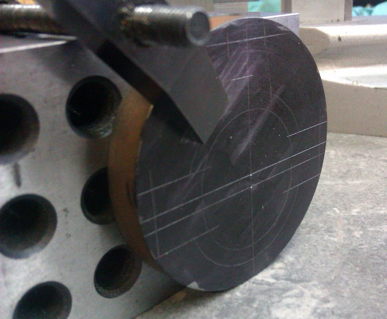
Just by locating an edge and then moving the cutting tool you can cut plenty of slots without any marking out, these were done that way both the circular grooves on the lathe and slotted top on the mill
Edited By JasonB on 02/02/2015 13:26:52 |
| Michael Gilligan | 02/02/2015 13:40:44 |
 23121 forum posts 1360 photos | Colin, I see you are posting today .. Have you lost interest in your Dial Indicator thread ? MichaelG. |
| Colin LLoyd | 02/02/2015 15:20:30 |
211 forum posts 18 photos | Hi Guys, MichaelG - no I haven't lost interest in the Dial Indicator thread. I was waiting until the stream of suggestions died down. But also It's just that as a novice - I didn't connect this item with that thread. Are you suggesting that I could arrange a plunger action (is this what they are called) dial indicator horizontally against the cross-slide and then use this datum to measure the required movement along the bed? Seems like a good idea and easily arranged. I'm guessing from Bob's contribution that DRO is Digital Read Out. I only have at this time a Chester Mini-Multi Lathe/Milling machine. No Digital Read Out. And I haven't used the dials as I haven't attempted to calibrate them yet - assuming some form of calibration is required (not even sure yet whether the markings are Imperial or Metric. JasonB - I saw these angle plates at the Model Engineers Exhibition at Alexandra Palace - I wondered what they were for - but didn't want to appear an idiot by asking anybody. Please excuse my basic questions, which to your experienced ears, may sound banal. Perhaps it might be a good idea to place against my name "knows f*!k-all".
|
| Michael Gilligan | 02/02/2015 15:49:40 |
23121 forum posts 1360 photos | Posted by Colin LLoyd on 02/02/2015 15:20:30:
MichaelG - no I haven't lost interest in the Dial Indicator thread. I was waiting until the stream of suggestions died down. But also It's just that as a novice - I didn't connect this item with that thread. . No, Colin, I wasn't trying to connect the two threads ... just trying to attract your attention. My recommendation on the other thread stands. MichaelG. |
| frank brown | 02/02/2015 15:53:31 |
| 436 forum posts 5 photos | The calibrations on your hand wheels are very accurate, so to mill your grooves across/along a piece of bar you just have to establish your datum edge and the edge of the bar. So the first thing you do is to purchase a pack of cigarette papers (the thinner the better, I have some white packaged ones , must be 20 years old). So stick a piece of the paper on the datum edge, switch on the mill and carefully bring it up until it whips the paper off. Note handwheel reading and direction of travel. Drop the table and wind on the necessary distance, calculate it on a piece of paper. Move the cutter out of the way (right angles to first datum check). restore table height and go ahead. Off course you can use an edge finder, but then you have to allow for the diameter of it, its all too much for my little brain. The only thing to check is that if you set the datum by moving the table from right to left, then all movements must be finalised by a right to left motion. I actually use white cardboard for my notes (ex Christmas cards), it survives the odd soaking in suds. Frank Edited By frank brown on 02/02/2015 15:54:30 |
| Bob Brown 1 | 02/02/2015 15:58:29 |
1022 forum posts 127 photos | I think the first thing to work out would be is the machine metric or imperial, sometimes they state on the machine like mm or imp but it should not be to hard to work out. Take a look at the dial on the cross slide, what does it say when rotated one revolution? Bob BTW for a novice a low cost DTI and magnetic base will probably do to start with no need to worry about the nearest 0.01mm Edited By Bob Brown 1 on 02/02/2015 16:03:13 |
| JasonB | 02/02/2015 16:06:27 |
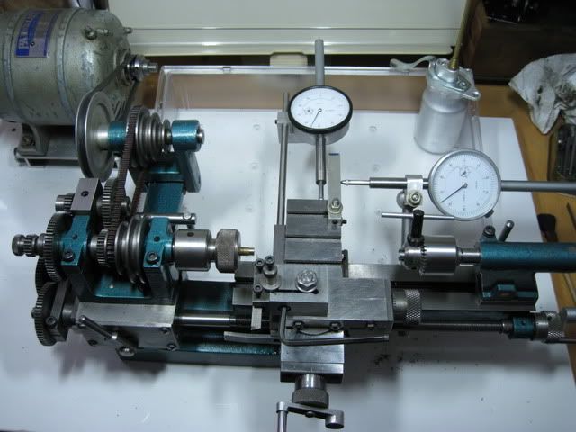
25215 forum posts 3105 photos 1 articles | Colin you can use a cheap 2" or 50mm travel plunger type dial gauge fixed to the lathe to give you better readings than your handwheels and also eliminate the problem of backlash, here is a friends Cowels so equiped. Arc should have something suitable.
Thats actually a 1-2-3 block in the photos but anything that is square will do to hold the work upright while you mark it out. An angle plate is "L" shaped with sloys in it for clamps etc, found a pick with one being used to hold a crankshaft that I was marking out that also shows the height gauge
|
| CotswoldsPhil | 02/02/2015 16:13:06 |
 196 forum posts 112 photos | Hi Colin, I think we would all agree, there are very few silly questions. Coming up with different solutions keeps the grey matter working. One way may be to arrange a clamp as a stop and a 3 mm drill as a gauge. Once the first cut is complete, move the slide until you can just interpose a 3 mm drill, complete the second cut. Remove the drill, reposition clamp, make 3rd cut, interpose drill, move slide up to the stop, voila positioned at next cut. Repeat as many times as necessary. There may be a small accumulated error but probably less that marking out and trying to position using Mk1 Eyeball. You could reduce the error by using 3, 6, 9 and possibly 12mm drills, instead of moving the stop each time. Regards
Phil H
|
| Colin LLoyd | 02/02/2015 17:09:09 |
211 forum posts 18 photos | An allied question now: I've been squaring up the 12mm square aluminium bar (that I am milling the 1.5mm channels in) that is held in a machine vice attached to the lathe cross-slide by using a larger end-mill (4mm but not critical) in the following way. With the machine vice reasonably tightly bolted down, I run the mill cutter along the back face of the aluminium bar so that any pressure to the back of the bar causes a slight change in the machine vice location. Once there is no discernible change I fully tighten the machine vice down (and check the tightening has not moved the alignment). Then I do the same to the top of the aluminium bar which is held finger tight in the vice. This is easier as not only does any downward pressure as the mill tool moves over the surface re-align the bar but there is visible evidence from a slight scratch mark on the bar surface. Having got the bar horizontal, I tighten fully the vice (and again check the alignment has not been moved). This appears to be good enough for my needs, bearing in mind that Brian May (of Queen) and his dad built his guitar (that I am making a copy of) with just files. Now I probably know from the above replies that I should be using a dial indicator (that I haven't got yet) but does the above make sense from a belt-and-braces point of view. |
| Chris Trice | 02/02/2015 19:19:44 |
 1376 forum posts 10 photos | Can't you just measure the feedscrew thread and turn the handle the appropriate amount? That's what the handwheel graduations are for and couldn't be simpler. Much simpler than buying an indicator you don't need because the handwheels do the same job. |
| Chris Denton | 02/02/2015 22:05:08 |
| 275 forum posts | A method I use for not particularly accurate parts but parts with a lot of curves and holes and things is to design it on AutoCAD on the computer then print it out on normal paper. Then use double-sided tape to stick it on top of the workpiece. You can even mark the radius centre point on the printout so it's very easy to line up on the milling machine. I made something today with this method and was a very good fit with the part it mates with. If you can line up the cutter with the lines well then it's surprisingly accurate. I make a crosshair shape on the computer where the radius centre point is and can then line it up with a dead centre fitted in the milling machine spindle. |
| Colin LLoyd | 03/02/2015 10:52:26 |
211 forum posts 18 photos | Hi Chris, Yes and I will once I have confidence in the accuracy of the graduations on the feedscrews. This is my first lathe/milling machine (2nd hand and just 2 months with it so far) and I'm still coming to terms with both it and what a lathe/milling machine does. So its a steep learning curve at present. I intend to use a Dial Indicator (once it arrives) to check the accuracy and resolution of the graduations. Having done that, I will be in a better position to do (and trust) what all experienced machinists do - use the graduated feedscrews. Until then, I'm just relying on visual belt-and-braces approaches for what I need to do. Luckily, at this stage of my education, the items I am making are not critical in either dimensions or in themselves. So if they are slightly "out" or even wrong, its not too difficult to just accept, or make another one. |
| Chris Denton | 03/02/2015 11:46:31 |
| 275 forum posts | I recommend the Harold Hall beginners books that Amazon sell them. You'll learn more reading those than months of just trying things
What's your background out of interest? |
| Howi | 03/02/2015 11:51:29 |
 442 forum posts 19 photos | Posted by Colin LLoyd on 03/02/2015 10:52:26:
Hi Chris, Yes and I will once I have confidence in the accuracy of the graduations on the feedscrews. You don't need to check the graduations Colin, you can't adjust or do anything about it anyway. You will find they are pretty accurate as is. |
| Colin LLoyd | 03/02/2015 12:18:45 |
211 forum posts 18 photos | Hi Chris (Denton), Yes - got a lot of books - several of the Workshop Practice Series, etc. and gradually working my way through them - but getting down and dirty is much more fun than reading books. Background: I'm a retired Climate Change Micrometeorologist who has spent 40 years working out energy and carbon balances in difficult parts of the world (Amazon, Sahara, Arctic, Siberia, etc.). Lacking access to workshops and sophisticated machine tools, and needing at times to repair sophisticated electronic and mechanical sensor instrumentation, I've developed an ad-hoc approach to working with metal, wood and electronics (my type of instrumention was expensive, and so instrument duplication and/or spares was often difficult to justify financially - and return for repair could waste 2-3 months of data taking time). So I have a good feel for materials and their characteristics and a good grounding in the use of what ever hand-tools I had. But I have never used a lathe or milling machine before. And my current hobby of making electric guitars does not need the precision in wood that metal requires. So this is all new to me. But I do like the precise nature of working with metal and what a lathe/milling machine is capable of. My father was a toolmaker/fitter by trade - but he usually worked with wood at home and left his metal skills at work. As a boy, I was impressed when he did arrive home having made an eccentric-geared tool that cut square holes in metal - worked like that fairground ride that flings a seat towards a corner - only for it to rapidly then move away again. |


Please login to post a reply.
Magazine Locator
Want the latest issue of Model Engineer or Model Engineers' Workshop? Use our magazine locator links to find your nearest stockist!
Sign up to our Newsletter
Sign up to our newsletter and get a free digital issue.
You can unsubscribe at anytime. View our privacy policy at www.mortons.co.uk/privacy
Latest Forum Posts
- *Oct 2023: FORUM MIGRATION TIMELINE*
05/10/2023 07:57:11 - Making ER11 collet chuck
05/10/2023 07:56:24 - What did you do today? 2023
05/10/2023 07:25:01 - Orrery
05/10/2023 06:00:41 - Wera hand-tools
05/10/2023 05:47:07 - New member
05/10/2023 04:40:11 - Problems with external pot on at1 vfd
05/10/2023 00:06:32 - Drain plug
04/10/2023 23:36:17 - digi phase converter for 10 machines.....
04/10/2023 23:13:48 - Winter Storage Of Locomotives
04/10/2023 21:02:11 - More Latest Posts...
- View All Topics
Support Our Partners


Shopping Partners
Subscription Offer

Latest "For Sale" Ads
- Reeves** - Rebuilt Royal Scot by Martin Evans
by John Broughton
£300.00 - BRITANNIA 5" GAUGE James Perrier
by Jon Seabright 1
£2,500.00 - Drill Grinder - for restoration
by Nigel Graham 2
£0.00 - WARCO WM18 MILLING MACHINE
by Alex Chudley
£1,200.00 - MYFORD SUPER 7 LATHE
by Alex Chudley
£2,000.00 - More "For Sale" Ads...
Latest "Wanted" Ads
- D1-3 backplate
by Michael Horley
Price Not Specified - fixed steady for a Colchester bantam mark1 800
by George Jervis
Price Not Specified - lbsc pansy
by JACK SIDEBOTHAM
Price Not Specified - Pratt Burnerd multifit chuck key.
by Tim Riome
Price Not Specified - BANDSAW BLADE WELDER
by HUGH
Price Not Specified - More "Wanted" Ads...
Get In Touch!
Do you want to contact the Model Engineer and Model Engineers' Workshop team?
You can contact us by phone, mail or email about the magazines including becoming a contributor, submitting reader's letters or making queries about articles. You can also get in touch about this website, advertising or other general issues.
Click THIS LINK for full contact details.
For subscription issues please see THIS LINK.
Digital Back Issues


Donate

 Register
 Log-in
Model Engineer Magazine
- Percival Marshall
- M.E. History
- LittleLEC
- M.E. Clock

ME Workshop
- An Adcock
- & Shipley
- Horizontal
- Mill

Subscribe Now
- Great savings
- Delivered to your door

Pre-order your copy!
- Delivered to your doorstep!
- Free UK delivery!
All Forum Topics > Beginners questions > How to Mark Out