Forum sponsored by:

New technology in Model Engineers Workshop
The way forward.
| John McNamara | 21/10/2014 13:40:46 |
 1377 forum posts 133 photos | Hi All Its been a while since I started this thread......Gee time is on the wing. Bit by bit I am gathering the tools and ideas to build a small CNC Mill. I know I could use a Chinese high speed ER collet spindle; EBay is full of them, the trouble is they do not lend themselves to quick changing and setting the cutting tool. As an alternative just maybe making a DIY spindle is doable. A fair amount of lathe and lapping. I do not have a cylindrical grinder. OK a workshop made spindle may be less accurate and durable than a commercial product but it will be affordable, and there is the pleasure of making it. Anyway I am drawing one up. Before I do That a bit of research. I am tending to think BT30 will be the best choice for the nose taper. I don't want a huge spindle and 30 taper tooling can be found at markets etc. It also reduces the bearing sizes (and prices) Has anyone found other high speed spindle documents that may be of interest in this area? Regards Some are slow to load all tested OK. I found this paper on spindle design: Also this brochure from NSK: I used this Google search: Edited By John McNamara on 21/10/2014 13:46:08 Edited By John McNamara on 21/10/2014 13:52:14 |
| John McNamara | 21/10/2014 15:18:42 |
1377 forum posts 133 photos | Hi All Also found this NSK Manual Very well written. Regards |
| Neil Wyatt | 21/10/2014 16:50:01 |
 19226 forum posts 749 photos 86 articles | Hi John, What about this: http://www.model-engineer.co.uk/news/article/lathe-bearings/19136 ? Some very practical arrangements there that would also work with angular contact bearings. Neil.
|
| John McNamara | 22/10/2014 13:57:43 |
1377 forum posts 133 photos | Hi Neil Hi All Thank you for the links, for slower speed designs easy to do. Higher speeds 15000 RPM being my target is not so easily achieved using tapered roller bearings.in the larger sizes 80 to 100mm OD, a speed mostly beyond their specified capabilities. Interestingly thin parallel roller bearings with tapered bores that allow them to be set up with preload (that have no axial stiffness only radial stiffness) are being used in some of the high end NSK spindles as shown in the NSK documents to be found at my last link. not as the end support bearing but in pairs at the business end of the spindle in combination with angular contact bearings. Interestingly my lathe has the same parallel roller bearing with a tapered bore for the front headstock bearing, In this case backed up by roller and thrust bearings. However the lathe has a top speed of 2500RPM although mine is slower being a long bed version for safety. I really like the NSK designs. I was surprised to find them on the net having had an old paper version in my files;.very nicely detailed and dimensioned too, together with the speed rating for the particular design, This takes a lot of the guess work out of achieving a soundly based design. . I know I will get serially stressed when I ask a bearing supplier the cost of the bearings themselves from NSK but maybe there are lower cost alternatives. Making the spindle housing, The end caps spindle itself and bearing retaining nuts will be an interesting exercise in lathe work. Obviously that will be the easy part getting the bearing mounting surfaces up to the required accuracy will be another matter, I will have to hone my lapping skills (Pun intended). A larger lathe will be preferable although I have seen some amazing setups on bench lathes in my time. Anyone that can turn and bore and hone a set of cylinders for a steam engine should have little difficulty making one. Finish grinding the tapered socket for the tool holder on first thought might appear difficult. It is not! I have done that procedure before by mounting the finished spindle set up with its bearings in place on a steel table and using a small precision slide set up at the correct angle with a small die grinder attached set up at the spindle centreline. I ground the taper in situ. I used a small gear motor to rotate the spindle while passing the grinder in and out. I got the run out to around a tenth .0001". Very satisfying. Many commercial spindles are finished in the same way Note the simple ball bearing type pull stud clamps used in the NSK designs a lot easier to make than the claw type often used. Hardened and tempered pull studs are available at modest cost... within the spindle housing there will need to be a hardened surface for the balls to bear against, this could be made easily, then hardened and Loctited in place. The ball carrier at the end of the draw bar will also have to be hardened and tempered Yes it would be easy to order an Asian spindle on the net, but they are not quick change and have limited torque. For a drive I plan to use a 2800 rpm AC motor driven via a VFD. in direct drive that gives a speed range of (depending on the motor and drive) maybe 500 to 4500 rpm in direct drive. However it will not be directly driven instead a two step (preferably) or three step pulley system. say 3.4 to one geared up and 3.4 to one geared downGiving a speed range of about 147 to 15300 RPM with reasonable torque throughout the speed range. the final ratios would need to be checked against the Motor drive selected. and the speed range of the machine required. FADAL in the US used this drive setup on many of their machining centres with a rather ingenious and easily built air operated selection system. The above are my investigations so far. I jhave never built a high speed spindle I have built one that worked at 4500 RPM Using NT40 taper tooling with a threaded drawbar.... That worked fine. High speed I know will be a lot harder. Anyway it will be a fun project. Time to hit the drawing board.. I would really appreciate hearing from anyone in here who has built one? Please post or PM. Regards |
| John McNamara | 27/10/2014 12:20:02 |
1377 forum posts 133 photos | Hi All Spindle Design. Only a draft but 90% of the design work is completed. ISO 30 is the smallest of the commonly used machine tool spindles (HSK a newer system is becoming more popular but tooling is harder to get and more expensive) Water cooled for higher speed operation (Very few commercial spindles have cooling) This is a Plus. At least 12,000 RPM (With low cost commercial bearings) operation, other commercial spindles using 9009 size 45 x 75 x 15mm 15 DEG angular contact bearings 15,000 RPM using high accuracy bearings. The Rear bearing is a dual row tapered roller (Tapered bore also to set the clearance). I have allowed for Grease lubrication only. pressurised oil mist lubrication could increase the speeds by maybe 30% but a lot of work to do and the oil mist has to be dealt with it is a health hazard. The water cooling makes Grease work at higher speeds It will be interesting what sort of temperature rise we get? Spindle body can machined from heavy wall tube And a small amount of bar sliced for the ends or bar stock depending on what is available in a makers shop.. The spindle body can be machined in two parts To assist builders with smaller lathes. Not shown is a turned between centres mandrel..... not fancy just a piece of scrap bar coated with automotive body filler then turned in one setting to locate the two steel body sections and keep their axis perfectly in line while they are being glued together, it will be discarded when the main casting has been poured around the spindle body. Formwork for the casting can be made from available material MDF wrapped in polythene works well and it does not stick. This is not an east job to make; a fair amount of lathe work and grinding if a machine is available, or hand Lapping, Slower but doable. The spindle nose taper will be ground in position after the spindle is completed. The drive system planned is a 3 KW 2800RPM motor with VFD I have only shown one pulley but two would be better Maybe 3.5:1 geared up and 3.5 to one gearing down. allowing for a VFD motor combination that can work effectively between 25 Hz and 100 Hz should give a reasonable torque at the lower speeds and the higher speeds required for small end mills. The readily available ER Manual hand tightened collet, Chinese high speed spindles loose power at lower speeds. I already have a set of bearings and the epoxy I will have to hunt up some steel and the Belleville washers. I will have to buy a length of pre hardened (machineable) steel bar for the spindle itself. Its a pity I don't have a cylindrical grinder, that will keep me busy lapping it to size. Its getting close to dirty hands time.....Always fun. What do you think? Regards  Edited By John McNamara on 27/10/2014 12:37:00 Edited By John McNamara on 27/10/2014 12:49:43 |
| jason udall | 27/10/2014 14:29:54 |
| 2032 forum posts 41 photos | ..watercooled... Yep..Mazak machines do that...also "wrap" the spindle motor round the spindle.... Very very agile. .... |
| JasonB | 27/10/2014 15:03:49 |
 25215 forum posts 3105 photos 1 articles | Just don't have a watercooled machine in an unheated workshop, I know of someone who had a watercooled router spindle that cracked in cold weather over the weekend |
| jason udall | 27/10/2014 18:00:50 |
| 2032 forum posts 41 photos | Water cooled in unheated workshop.... Mmm guess thats why mazak used antifreeze. ....now if you want to talk about water freezing in the air mains...then yes it can be a pain As does the coolant...now thats a real chore to thaw out.... Edited By jason udall on 27/10/2014 18:02:08 |
| John McNamara | 13/11/2014 13:30:07 |
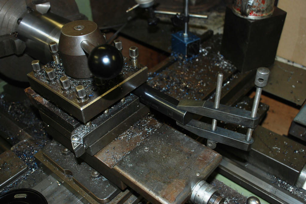
1377 forum posts 133 photos | Hi All The Spindle design is finished now I am starting work on building one. Being the largest part I am starting on the body. Ideally made from a bar of steel about 120mm in diameter by 320mm long, something I do not have lying around the workshop. I did however have two chunks of steel that had been used as very heavy bench weights, they were covered in rust and had a handle welded on but they were big enough for the job including a join, so I set about grinding off the handles and then I skimmed them all round to see what sort of steel they might be? Once I skimmed them I knew they were not cast iron, the curly malleable chips proved that as did the shine of the surface. I was hoping the welds once skimmed off would leave soft metal, that was not the case the steel under the weld was very hard; the cooling weld had chilled the metal of the bar itself hardening it for a depth of maybe 5mm. That would indicate that the weights were some sort of carbon steel. They had come from a sheet metal works when it closed down, Maybe they were for making dies. One benefit of the smaller pieces is that I can work on them more easily. drilling and boring a piece 330mm long would not be easy, a piece 150mm long is a lot easier to work on. I started out drilling a 14mm hole in the centre of the bar using the lathe, I happen to have a drill long enough so I drilled straight through, although it could be just as easily done from both ends even if it does not line up perfectly it does not matter it will be close enough. I then passed a 25mm drill through making the hole big enough for a small boring bar, that I used from both ends as it was not long enough. the hole was widened to about 45mm. Finally the hole was big enough for a big boring bar that can handle the overhang required to pass right through the work without chattering. The setup in the 4 jaw chuck is not ideal with a large overhang for such a large piece I kept speeds down and the cuts light to reduce the chance of the work moving in the chuck. Before the finishing cuts were taken I re-trued the bar in the 4 jaw chuck very carefully (both) near the chuck and at the overhanging end to make sure the work piece was running perfectly true. The final step were to bore the 100mm deep x 75mm diameter recess for the stack of 4 angular contact bearings that will support the work end of the spindle. I made the fit a firm push fit rather than a press fit to make adjusting and servicing the spindle. Once the pocket was complete the outer edge and face of the spindle body was turned assuring it was concentric with the bore and that the face was perfectly square the same the bearings also press against a 5mm step at the bottom of the bored hole, this was also finished turned in the same setting.In this design there is no threaded nose piece to preload the bearings instead an end cap is bolted on the face using packers to set the preload. This will be done later. If you study the photos you will notice there are sparks flying off the tool as I make the finishing cuts. The cuts were taken at 1200rpm (And this was on a 110mm diameter that's about 1360 surface feet per minute cutting tough carbon steel even the hard bits left by the welding were peeled away) As fast as my lathe will go using a three thou depth of cut and a feed of .002" and I got a very nice finish.... Using a ceramic insert! My neighbour is an engineer and he gave me a holder and some tips. All I can say is wow! the metal just fell away as sparkles leaving a very nice finish. if you get the opportunity to try a ceramic insert you will be surprised. Don't try this with a carbide insert it will not survive. Ceramic inserts do not like interrupted cuts they will chip my friend warned. And they do like speed. below 600 RPM the finish was not as good. I think its to do with the heat, the metal appears to be wiped off I guess its physics at work. Over the weekend I hope to prepare the other half of the body...... Images to follow. Edited By John McNamara on 13/11/2014 13:51:50 |
| John McNamara | 13/11/2014 13:53:09 |
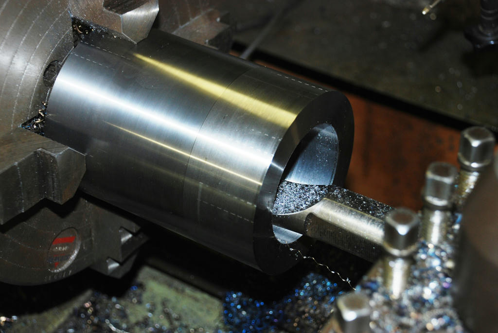
1377 forum posts 133 photos | BT 30 Spindle Front Half Boring Pocket
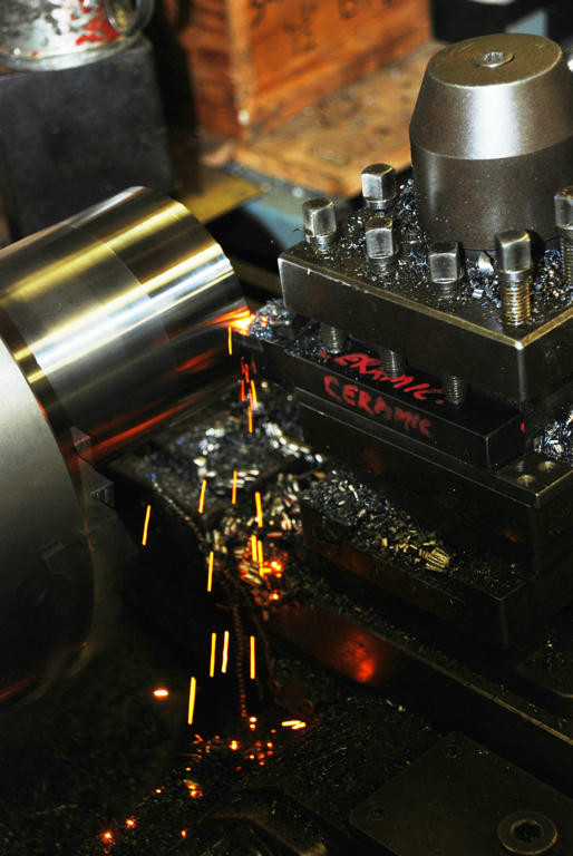
Ceramic insert at 1200 RPM
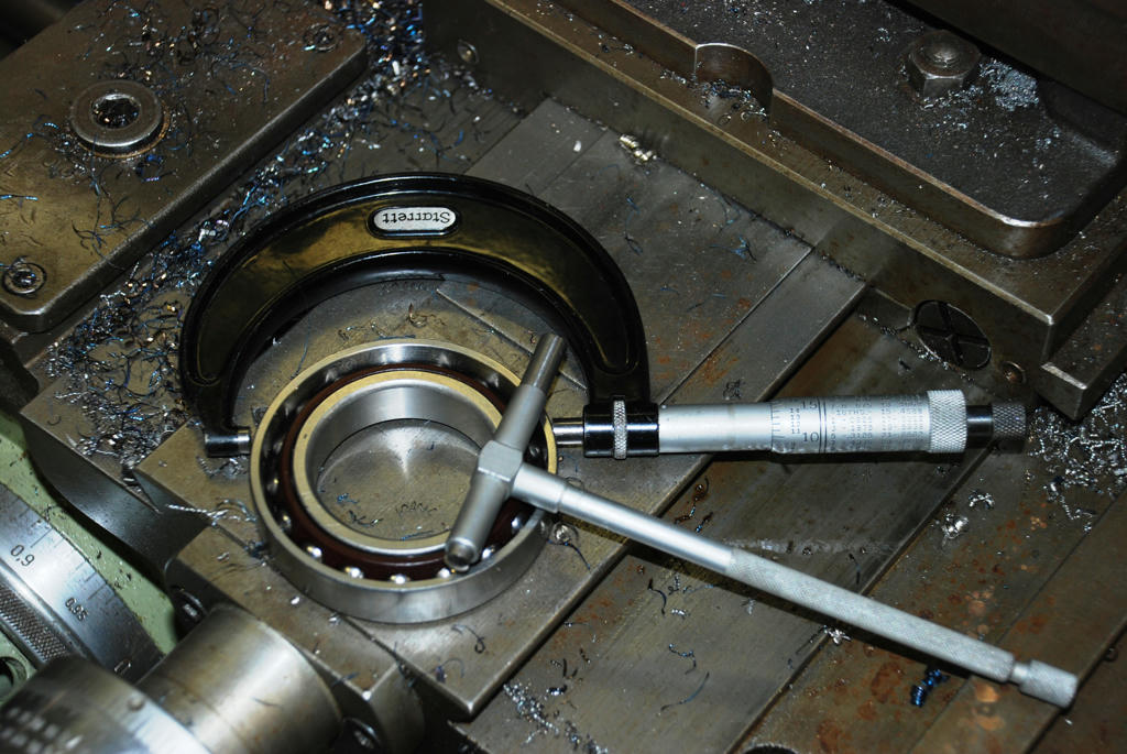
4 75mm bearings will be used
Clamp is for vibration damping
Edited By John McNamara on 13/11/2014 14:03:45 |
| Mark Wrathall | 25/01/2015 11:20:58 |
| 1 forum posts | Really cool job you did on the Epoxy/Granite tool grinder, and now the BT30 spindle. I have aan old Deckel G1L pantomgraph frame for which I am making a new BT30 head. THe support arm is in progress and will be E/G. Look forward to your next update.
Regardsm Mark |
| andrew winks | 25/01/2015 14:37:42 |
 117 forum posts 1 photos | No coolant with the ceramic toolbit?? Amazing cutting and finish. |
| Muzzer | 25/01/2015 14:45:53 |
 2904 forum posts 448 photos | 15000rpm sounds pretty fast. You will need to make sure the rotating parts are very well balanced, including the tooling - how do you plan to do that? The tool holders that are balanced for that sort of speed are pretty expensive. The speed suggests small cutters (in a large toolholder) and the relatively limited power (3kW) will limit the speed with bigger cutters. I'm looking at the central pull shaft with its Belville washers and the words "whirling shafts" come to mind. There's very little defining the radial position of the thing at its middle and it's very long. Every shaft has a critical speed at which it will whip. I made a similar ball and ramp quick release toolholder for my NMTB30 nose. Although there are many std pull studs out there, by the time you factor in the ball bearings and the closer, many of them are simply too big to fit in the space available so I ended up making my own (small) pull studs. You probably have more space than I did but even so it may be a challenge to find something that works. BTW, there are insert grades that are designed for interrupted cuts. If you find you are suffering from damaged edges, it may be worth checking what grade you have and getting something better. You don't generally use coolant with inserts in our applications. The heat generated is key to the cutting effect so coolant would be counterproductive and can cause thermal shock effects. The exception would be parting off, where our machines lack the power and rigidity to run at "design" speeds. Murray |
| Muzzer | 25/01/2015 16:36:24 |
2904 forum posts 448 photos | I've never used a ceramic insert myself. They seem to be capable of "several orders of magnitude" reduction of machining time compared to carbide. I doubt any of us have machine tools in our sheds that are anywhere near capable of exploiting them but perhaps one day(!).... Interesting intro article here. Murray |
| John McNamara | 25/01/2015 23:56:36 |
1377 forum posts 133 photos | Hi Muzzer Yes it is fast and balance will be problem if vibration is an issue I will have to send the spindle out for professional balancing. I have just finished machining the body parts and am almost finished the spindle rotor itself. The Bellville washers are supported by the pull stud and to resist whipping note the solid area in the middle of the washers I placed the support piece there to reduce the length of the slender pull stud, it is a sliding fit in the bore of the spindle and on the stud. If necessary I could use two dividing the shaft length into thirds, although I do not think that will be necessary. I did not use the ceramic inserts for heavy cutting just finishing, the power requirements for finishing are smaller than you may think, at high speed the metal is so hot it is effectively wiped off. Coolant is not recommended due to heat stress on the tip. Regards
|
| John McNamara | 26/01/2015 00:33:26 |
1377 forum posts 133 photos | Nice work! Your quick change system Muzzer..... |
| John McNamara | 26/01/2015 14:04:43 |
1377 forum posts 133 photos | Why not give it a try John aka bogstandard2 Maybe you could cludge up a quick clamp to test if the material is suitable? Then If it works make a proper holder. Dimond should work fine sharpening it. The inserts I have are just squares with 90 degree edges, without a chip breaker, to be used in a negative rake holder. I am still on my first square out of a small packet. Strangely even if there is a small chip on the edge unlike carbide which will make a terrible mess the ceramic insert was still OK for finishing it kept on working.obviously not so good if turning up to a precise corner radius but Ok for turning down a shaft. Regards PS I am setting up a Website using Joomla, A bit of a learning curve but after a week of trial and error it is starting to take shape! If you are thinking of setting one up Joomla is worth looking into. Joomla is Open source supported software (Free) They claim about 3% of the sites in the net use it, that is quite a few million sites.... You can set up a basic site without using programming code. (it is menu driven) I have been following the (British) video tutorials (given by one of the founders) there are links on their site. There is also a link to siteground who offer quite inexpensive hosting plans. They offer a free 90 day fully functional demo website... Yes it is on the web so you can share the URL with your friends. I have no personal connection to these organisations. Regards |
| John McNamara | 13/02/2015 14:10:44 |
1377 forum posts 133 photos | Are computer generated designs copyright? Hi All I know this post is not quite Model engineering, Although most of us at one time or another had an Idea they thought had merit and have wondered on the we may go about producing it. It does deal with new technology the subject of this thread. I also know that many of our members have worked or are still working in Industry and may have pondered on some of the questions I ask below. As a class of 69 person, when I started off a design was put on paper and the "plans" were put in a safe place. Sure, others could copy a design by measurement and make a physical copy but the original was often better because of the difficulty of reverse engineering the design. More importantly reverse engineering is costly and very time intensive. The same applied to the music industry and records. You needed a record pressing plant to make records in the pre digital age. Anyway music is copyright material and protected somewhat, at least from commercial copying. Ahem the Internet there. These days paper drawings are mostly used for a quick sketch and the final drawings are drawn and stored on a computer. There are two main ways to store a drawing on a computer, as a bitmap which is simply an array of coloured dots (pixels) like on the screen you are viewing, or in vector form. All the manufacturers of Computer Aided Design software (CAD) use vectors to store the image. A vector is a line or arc in XYZ space between two or three points. Most often the definition is accurate to twenty or more decimal spaces, very accurately indeed. As well as the Vectors describing the image of the work there is a set of instructions telling the recipient reproducing machine how to interpret the information - CAD files are big because of this. This information stored on a file can replicate an article accurately with far better than millionth of an inch accuracy, and this information can be copied and stored on a 50c disk or sent anywhere via the internet in a few seconds. Possession of the software image allows the holder to insert the program in a CNC machine and reproduce it as many times as needed. There are many third parties involved in the production of a work. Laser Cutting for instance is most often done by specialist contractors. You give them a file and they return the work often completed in a day or maybe two. For a 50c disk they can reproduce your work and sell it to all comers. Laser cutting is unusual in that it actually does copy the drawing as a flat image cut out of a flat sheet. The same applies to water jet and plasma cutting, different technologies that achieve the same result. Interestingly if you study the sculpture you see in public parks etc. many of the objects will have been almost certainly reproduced from laser or other cut sheet. Was the drawing covered by copyright or only the art object ? Creating a design is a lengthy process, typically a small design will take several weeks, larger projects years. The ability to actually do it takes a lifetime - you never stop learning. There is a huge amount of effort embodied in creating a design. Is this a case where a clearly genuine creator has no intellectual property rights at all? While I have focussed this discussion on cutting a true copy of an image on a flat sheet, there is also similar design work in 3D , (3D printing) and more broadly 3D machining with cutting tools. All of the methods share the same design efforts and all are subject to the same easy to copy scenario. I think that the patent/copyright system has some catching up to do in this area. The information below sets out my expanded thoughts. Background: Recently I have been working on a machine that is mainly made from laser cut steel. maybe 90 % of the mass. It has been my primary objective to produce the machine as a flat pack that can be easily shipped and assembled. Or even better ship 10 % of the machine and locally produce the 90% with local laser cutting contractors. avoiding unnecessary shipping. Thinking about this process raises several issues, in particular the intellectual property rights I have embodied in the design. My research indicates It is generally agreed that the copyright right to works of art remains with the artist even after the work is sold (unless the right it is assigned to the purchaser). this covers paintings movies novels sculpture etc. But what of a set of CAD files hand drawn and created by me that represent the design in digital form? Just like a digital painting, a very popular art form these days..... I have attached a link to a short paper that contains the following... It covers 3D printing in the main but is worth reading Continued......... Edited By John McNamara on 13/02/2015 14:12:37 |
| John McNamara | 13/02/2015 14:14:27 |
1377 forum posts 133 photos | Quote from above link: " Copyright automatically protects those works from the moment they are written down (or painted, or filmed – the technical term is “fixed in a tangible medium". Copyright also protects an “original” work that is not unique in the world as long as the author as unaware of existing versions. In most cases, copyright protection lasts for the life of the author plus 70 years after her death. Finally, copyright infringement can be an expensive proposition. The law allows rights holders to assume – without the burden of actually proving harm – damages of up to $150,000 for wilful acts of infringement.8 All of this means that copyright is very easy to get, lasts a very long time, and is expensive to infringe upon. In contrast, patent covers useful articles – things that do things. Essentially, patent covers the types of things that you would look to an engineer or scientist to produce: machines, technical systems, and compounds. Unlike copyrights, you need to apply for a patent before you can get any protection." End Quote: OK my reading of this is the machine itself is not covered by copyright? But what of the CAD files and G Code that are used to produce it? Do I have copyright protection for those documents? Are they not the print in the book that may not be reproduced? Or the font in the book that is copyright. for example... You cannot get "Arial" from Google fonts because the design dating back to pre war is owned by the Monotype corporation. You have to pay a fee to use it. fair enough. (?Pre war the font was made from type metal it was a physical object that was protected by copyright.) When you go to a public library you may not copy more than a small percentage of a work due to copyright. Any movie digital or film is protected or any photo. Or the riff at the start of a particular rock song; a recent case to Look up "Men at work" "down under" vs "Kookaburra sits in the old oak tree" and the old bird won. I Would like to assert that the use (IE reproduction) of the design I have created would infringe on my rights under copyright law, and further that partial copying beyond a small portion of the work as with books also infringes. The laser cutter is simply my paint brush or pencil. once it starts to draw my unique brush/Pen/Laser strokes it has to be with my permission. I would be very interested to hear of other members experiences in this area My argument is that it is not possible to use the CAD file and G code to replicate the object without infringing. Once you issue a cease and desist order claiming copyright protection, how does the person reproducing the design claim it is their work, if they cannot and clearly you can how does the infringer defend themselves? OK they can change it slightly... Or can they? they cannot if it is a book a font or a piece of music etc as mentioned above. So If I give the file to a laser cutter and order a run; does it mean that that person can then reproduce the item any time for anyone without my permission or is the design my property? Lets look at the process. the drawing is loaded into the CNC system. for reproduction the same way a book is loaded into the typesetter pre printing. The cutter cut's the drawing into a sheet of material creating an image. When its finished the reproduced design is sitting on the bed of the cutting machine, faithfully reproducing my drawing in full, at that point a copy of my drawing exists. it is not a machine just a reproduction of the drawing. It might become a machine later... or a sculpture? that may occur later. however until something is done to it is a copy of my drawing. and that is not allowed under copyright. Continued......... Edited By John McNamara on 13/02/2015 14:29:29 |
| John McNamara | 13/02/2015 14:20:11 |
1377 forum posts 133 photos | Continued from previous page..... How could a copyist argue that the design reproduced in full is his property? The output of a CAD program is indeed a piece of software, a unique set of instructions that replicate a unique image created by a person. even if the software is never used and sits on a disk it is the originators property, I am arguing that the originator owns it and no person has a right to have possession of it without permission. Without it no replicated image can be made at all Just like a fingerprint it would be easy to prove that the image stored on media was generated by the unique set of instructions. thus proving the copyright work in this case a CAD file had been stolen. proving the copyright work in this case a CAD file had been originated by a particular creator. The mathematical description of an image in a CAD file has many thousands to millions of variables. I am sure an expert mathematician would find little difficulty in proving uniqueness. The originator also will have contemporaneous notes sketches etc. to prove the he or she is the originator of the work. The online Oxford Dictionary defines Software as.... "The programs and other operating information used by a computer:" "Other operating information" covers a lot of ground A CAD file is not a bitmap. It defines the lines and arcs mathematically object by object. it is a set of instructions. not an image file. I would really like to see this tested in court. (or maybe there is already precedent)? I was rather hoping that more of our forum members has knowledge on this subject? Here is another article worth reading - it deals with what is software.... Continued........ Edited By John McNamara on 13/02/2015 14:42:00 |
Please login to post a reply.
Magazine Locator
Want the latest issue of Model Engineer or Model Engineers' Workshop? Use our magazine locator links to find your nearest stockist!
Sign up to our Newsletter
Sign up to our newsletter and get a free digital issue.
You can unsubscribe at anytime. View our privacy policy at www.mortons.co.uk/privacy
Latest Forum Posts
- *Oct 2023: FORUM MIGRATION TIMELINE*
05/10/2023 07:57:11 - Making ER11 collet chuck
05/10/2023 07:56:24 - What did you do today? 2023
05/10/2023 07:25:01 - Orrery
05/10/2023 06:00:41 - Wera hand-tools
05/10/2023 05:47:07 - New member
05/10/2023 04:40:11 - Problems with external pot on at1 vfd
05/10/2023 00:06:32 - Drain plug
04/10/2023 23:36:17 - digi phase converter for 10 machines.....
04/10/2023 23:13:48 - Winter Storage Of Locomotives
04/10/2023 21:02:11 - More Latest Posts...
- View All Topics
Support Our Partners


Shopping Partners
Subscription Offer

Latest "For Sale" Ads
- Reeves** - Rebuilt Royal Scot by Martin Evans
by John Broughton
£300.00 - BRITANNIA 5" GAUGE James Perrier
by Jon Seabright 1
£2,500.00 - Drill Grinder - for restoration
by Nigel Graham 2
£0.00 - WARCO WM18 MILLING MACHINE
by Alex Chudley
£1,200.00 - MYFORD SUPER 7 LATHE
by Alex Chudley
£2,000.00 - More "For Sale" Ads...
Latest "Wanted" Ads
- D1-3 backplate
by Michael Horley
Price Not Specified - fixed steady for a Colchester bantam mark1 800
by George Jervis
Price Not Specified - lbsc pansy
by JACK SIDEBOTHAM
Price Not Specified - Pratt Burnerd multifit chuck key.
by Tim Riome
Price Not Specified - BANDSAW BLADE WELDER
by HUGH
Price Not Specified - More "Wanted" Ads...
Get In Touch!
Do you want to contact the Model Engineer and Model Engineers' Workshop team?
You can contact us by phone, mail or email about the magazines including becoming a contributor, submitting reader's letters or making queries about articles. You can also get in touch about this website, advertising or other general issues.
Click THIS LINK for full contact details.
For subscription issues please see THIS LINK.
Digital Back Issues


Donate

 Register
 Log-in
Model Engineer Magazine
- Percival Marshall
- M.E. History
- LittleLEC
- M.E. Clock

ME Workshop
- An Adcock
- & Shipley
- Horizontal
- Mill

Subscribe Now
- Great savings
- Delivered to your door

Pre-order your copy!
- Delivered to your doorstep!
- Free UK delivery!
All Forum Topics > Model Engineers' Workshop. > New technology in Model Engineers Workshop