Forum sponsored by:

Hot air and stirling engines
| Mark Smith 3 | 01/10/2009 10:35:18 |
 175 forum posts 36 photos | I found the problem with the infernal clattering noise. I locate the displacer rod in the base with a grub screw. The screw came loose and the displacer parted company belting its way independently in the cylinder. I need now to cut a groove in the rod to make sure it stays put. It has good power on gas; it takes quite a lot of grip on the shaft to slow it and even more to bring it to a stop. It seems to have most torque about a third of its full revs. |
| Ian S C | 01/10/2009 11:38:40 |
 7468 forum posts 230 photos | Circlip,I'll get a piece of bar 316 works ok for me,its not the best to machine (304 better),but I'v used 316 for other hot caps.I'll need 60mm dia,and I'll just see how long I can get,I'll use the existing threaded bit 6" from the end,I need 1 1/4" min length.I'v fixed the displacer,and the water leaks,and reassembled the motor,and run it,don't think its got the power it had before the repare!I re-epoxyed the cold end of the displacer after cleaning the oil from inside (not sure how it got there).Peined the end over the disc that holds the rod,then put dents in behind the disc.I might have to take the rod the full length and screw it at the hot end,or make that front disk brass or steel and solder it.The screw in your motor was in the hot end?so it would not be able to be locktited,but it maybe a good idea to lock it some how. |
| Circlip | 02/10/2009 11:24:55 |
| 1723 forum posts | Just as a rough guide Ian SC, 303L and 304L for general SS usage, 316L for Hygenics and 321 for heat apps. unless you want to go into the exotics like Inconels etc.
Used 321 grades exclusively for the zorst systems on the BR Diesel locos, Seemed to work quite well, sorry, Full size systems.
If you can get the "L" designations of those three, they are easier to machine (L for low carbon content), saves any fear of rusting, and oh yes they do. Ask the guys who built the Thames barrier.
Boring a Bar of material seems hard work, Know anyone with TIG welding facilities??
Regards Ian. |
| Ian S C | 02/10/2009 12:02:16 |
7468 forum posts 230 photos | Hi Ian,its mostly a case of what I can pick up,tried the outfit mentioned by Mark,but they only handle brass,bronze, copperand aluminium,but I got some addresses,but I think I'll check out the muffler repare shops,should be able to get welding done there also.316 is also used for marine work ie prop shafts.Yes boring thin shelled cups say 3" deep is a little tedious,and as you near the end of things a little nerve wracking,the first one was not that long after I got my lathe.The hot cap has an internal 32 tpi thread to attach it to the cold end just next to the water jacket,a good fitting fine thread seems to be enough to seal the joint,not needing O ring or gasket.'Frade don't always use the ideal materials,best is sometimes whats in the junk box. |
| Ian S C | 04/10/2009 11:05:49 |
7468 forum posts 230 photos | Been fiddling around with my version of Jan Ridders single cylinder vacuum engine that was in ME a while back,havn't got it to go yet,have to do a bit of thinking about it.I built one from a sketch plan in an old ME 10 yrs ago,that one took a yr or so to get going,it now runs like clockwork,so this one will possibly be something similar.I suppose vacuum motors are a form of hot air motor. |
| Mark Smith 3 | 05/10/2009 08:21:08 |
175 forum posts 36 photos | My pressurised engine is taking shape. The crankcase and side plates are complete with pressure guage and crank bearing set with two dynamic seals. Next step is to turn the piston and the displacer. I have installed a car valve so I can use my compressor to add pressure before I work out how to make the self pressurising pump. Ian how many engines do you make, Steam? Is a flame licker as powerful as a hot air engine or less so?I will post a pic or two of my latest engine and my vertical engine shortly. Edited By Mark Smith 3 on 05/10/2009 08:22:21 |
| Ian S C | 05/10/2009 12:43:10 |
7468 forum posts 230 photos | Flame Licker/Vacuum,that tells most of it,it opperates by the pressure drop as the flame that is drawn into the cylinder cools.Unlike the stirling engine that is a sealed system that is double acting,powered by both expansion and contraction,also it can't be improved by pressurisation.Steam,I'v built some oscillators,few yrs back the local high school had a night class and built one there 5mm bore.I then made one 3mm bore and another 1/4"bore,these two were put in boats and sailed on the lake at the local recreation ground,the 1/4" one wasn't powerfull enough so I made a V twin vertion,but I havn't tried it yet.I have got a 4 stroke open crank engine slowly(very)evolving.Built my first motor(thought I'd invented something new)a pop pop boat,then after I got it going dad told me he had one when he was a boy,I think I was 10yr old.Here endeth the history of Ians engines to now,IAN S.C |
| Mark Smith 3 | 07/10/2009 08:44:50 |
175 forum posts 36 photos | Very interesting history, Ian. You have done much more than me I am a tyro at this game but learning all the time. I have always been fascinated with engines of all types but non captured my imagination as the stirling engine with its simplicty of operation and its potential. Here is a photo of the first engine I built out of junk. It develops quite a lot of power on Gas. I found that if I hold the shaft at a certain speed the torque starts to increase steadily until the shaft gets hot under my fingers trying to slow it down; maybe someone can explain that..
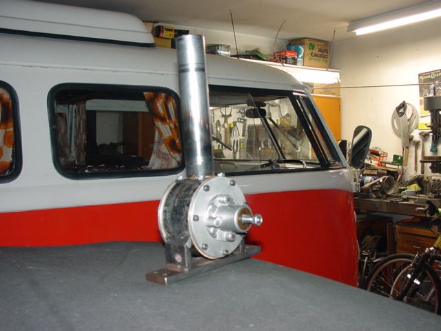
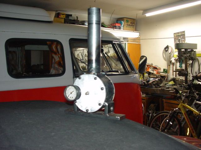
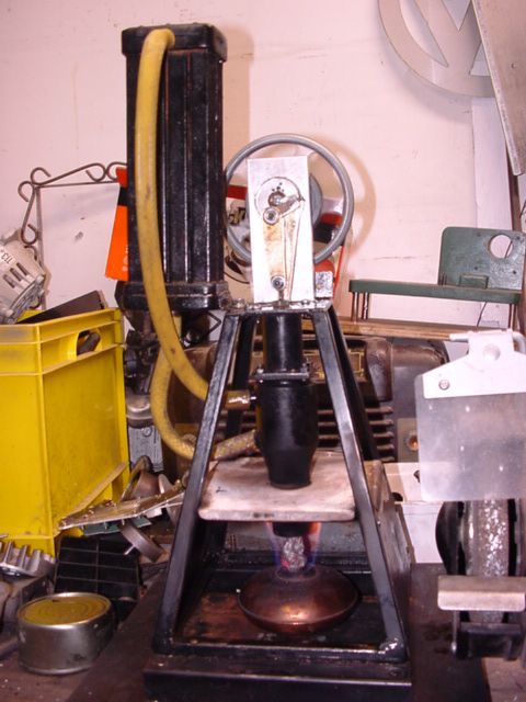 This engine has a 2cm stoke and a 2.5cm bore seen here running on meths. The next engine is my new one designed to be pressurised. It has a 3cm stroke and 3.3cm bore. The crankcase is from a car generator parted off in the lathe. I then mounted it in the four jaw chuck to face off the part to accept the cylinder flange; quite an undertaking. It made the floor rumble a bit. The cylinder is from a large shock absorber and the displacer is part of a bike frame (chrome molly). I now need to fashion the piston and seals which will be what I found successful to date, being leather cup seal in the piston and a teflon tape stuffing box to seal the displacer rod. I found the pressure guage in one of my junk boxes. At first I have installed a tyre valve to pressurise the crankcase from my compressor until I work out how to make a self pressurising pump driven off the opposite side of the piston from the main crank. I think the cup seal will equalise the pressure across the piston.The crank and seals I have modified from a line trimmer engine. I installed two seals in the bearing set to contain the pressure.
  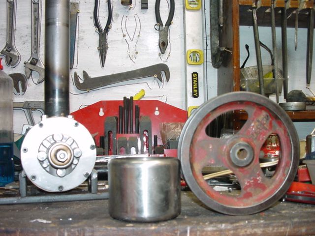 This last image is of a sugar bowl that will become the cooling jacket and the flywheel I think should work after some turning and truing; hope this is interesting. |
| Mark Smith 3 | 07/10/2009 10:13:50 |
175 forum posts 36 photos | Clive, Gordon and john wood where are you and what are you up to? |
| Ian S C | 07/10/2009 11:59:09 |
7468 forum posts 230 photos | Hi mark,twq of my first attempts at making engines were electric solinoid engines,I wrote a bit in ME vol163 no 3859 in 1989.The motor that I think I could pressurise looks similar to your latest,mine has a bore of 1 1/4" stroke power3/4" displacer 1 3/16".I read lately of making cup seals of Rulon (related to teflon but expands less with heat),the artical suggested using .015" then molded using heat,melting point of electrical solder is the indicator.I,m looking for something in the stainless ware ie sugar bowl,jug,mug,what ever 55mm dia inside,for the hot end of my biggest motor,think your one is to big for me so you'r ok.For a pressure pump,see Brian Thomas' self pressuriing stirling engine,it has a bore of 1/8",and the stroke is the same as the displacer,not sure could be 1/2". |
| Clive1958 | 07/10/2009 13:00:44 |
| 10 forum posts | Hi Mark, i'm still here, i've been trying to spend more time in the workshop and will hopefully post some picture of the results, I have been following the thread with interest. |
| Ian S C | 07/10/2009 16:34:25 |
7468 forum posts 230 photos | Hi clive,I'll be looking out for your pics,I havn't worked out how yet(too lazy)Good night all,IAN S C |
| Mark Smith 3 | 12/10/2009 05:47:32 |
175 forum posts 36 photos | I have to rethink the displacer drive. I had planned to use an offset crank as in my previous engines but the space between the crank and the bottom of the piston means too much angle and side thrust on the displacer rod. Going to go for a bell crank with a scotch yoke to drive the displacer. At some time I will have to find out how to case harden the slot. does anyone know how this is done? Told you I am a tyro.  Also the offset crank uses up the space I had planned for the self pressurising pump that I hope to install at some time. Also the offset crank uses up the space I had planned for the self pressurising pump that I hope to install at some time.Edited By Mark Smith 3 on 12/10/2009 05:49:38 |
| Ian S C | 12/10/2009 11:19:09 |
7468 forum posts 230 photos | Hi Mark,on my first engine,a V type I used a scotch yoke on the displacer so I could shorten the engine about 2".I made it out of aluminium.I cut the slot 3/8" wide,and 1 3/16" long,into that I inserted a bronze bush with a 1/4" slot 1" long,it ran on the 1/4" crank pin beside the con rod for the power piston.I'v got one on a water pump just running on the aluminium,seems ok.Yes you could case harden the slot,I use Kasenit,think I got it at George Henerys nearly 20yrs ago,I think they still have it.I have on a number of occasions heard of it being discontinued,mainly in Model Engineer.I'd just pack the slot with Kasenit powder,heat to red,hold for a few minutes,then quench in water,the remaining Kasenit will pop of leaving a clean gray finish,thats it no tempering required.If you can get some its well worth it,and it lasts as we don't use much.I think there are special grades of steel for case hardening,but ordenary mild steel works ok.Havn't used it much with my motors,but for hard pins etc I use needle rollers out of bearings,also some shafts out of computor parts are hard ie in old printers.Theres a thread on case hardening,sugests 90% charcoal 10% baking soda,might be worth a try. Edited By Ian S C on 12/10/2009 11:38:14 |
| Mark Smith 3 | 12/10/2009 22:12:51 |
175 forum posts 36 photos | Ok Thanks Ian |
| Mark Smith 3 | 15/10/2009 05:03:32 |
175 forum posts 36 photos | Closed everything up today and added pressure from my compressor. It leaked like a sieve until I coated all gaskets with cement. Now it will hold 120psi (dropping to 80psi) for 30 minutes. at this pressure It is almost impossible to turn over tdc. But for now I will concentrate on just getting it going at atmospheric pressure to work the bugs out. It seems tight in one place but I can't find the cause at present. Compression is very good with bounce but I need to add the big flywheel to help it over tdc as I have only been turning it with a flywheel from the line trimmer - too small.
I realise it will be impossible to start under pressure but was keen to see if the rotory seal on the crankshaft would hold pressure and it does, that's a start at least. |
| Ian S C | 15/10/2009 12:04:47 |
7468 forum posts 230 photos | Mark I would be starting at atmospheric pressure and slowly increasing possibly 5psi at a time,you may not get much above 20psi for effective performance gain,pressures above this seem to require rather sophisticated heating and cooling systems.performance improvement should be quite good,maybe double non pressurised.Some pressurised motors will not run without pressure.I suspect it might need a fairly heavy flywheel to get it going.I think would like to build something with a Ross linkage,just have to find some bits and see what happens.With these motors hot and cold cylinders generate power,the hot piston has a stainless hot cap on top.Just thinking,a bike pump might be all you need,and could be easier to regulate the pressure. |
| Mark Smith 3 | 15/10/2009 21:39:28 |
175 forum posts 36 photos | I will start the flywheel process today and, as you suggest, just get it going on atmospheric pressure to start with. I was just keen to see how much it would hold. There is a tiny leak in the hot cap (which I mig welded) I will get my son who is a very good welder to tig weld it for me as mig welding is hard to seal up on thin steel.
I too will look at the ross linkage at some point. Andy ross apparently got very good performance from his alpha engines probably because of the better 1:1 compression ratio. Have you seen the balanced rocker mechanism he has on an engine he installed in a locomotive http://www.ent.ohiou.edu/~urieli/stirling/andy_climax/climax.html Beautiful workmanship I am a million miles from that; just happy to make things work at this stage. Oh well back to the garage for me. I am on leave this week so get to spend plenty of time in there (don't tell her indoors!) |
| Ian S C | 16/10/2009 11:27:33 |
7468 forum posts 230 photos | Eureka,got the low temp motor going again,about 40rpm.Fitted newer,lighter bearings,and removed the cup seal,even with graphite powder workedinto the leather there was too much friction.At the moment the flywheel is the piece of waist I cut from the edge of the disc cut from the larger of the two fry pans that make up top and bottom of the motor.Outside dia 220mm,depth of rim 9mm x 5mm thick,and I used bike spokes for spokes into an aluminium hub.Gee weld bits,thats great,welding an end on a bit of tube-how thin can you go with stainless?I imagine TIG would be the ideal.That motor of Andy's is superb,'fraid mine are similar to yours.My only welder is an ordinary 140amp stick welder thet I occasionaly use to blob bits of metal on to other bits of metal,sometimes they seem to join together. |
| Ian S C | 17/10/2009 12:22:52 |
7468 forum posts 230 photos | Mark you asked about the power of flame lickers,I ran my one working one tonight with a little water pump,it did'nt pump much water,but kept it running at 60 strokes per min,can't remember the reduction but I think the motor would be doing 200rpm or so.The way I was running the thing I need at least 3 hands,if I set it up I think it would pump at 100 spm.The pump is 1/2" bore x 3/4" stroke,and it was lifting the water about 1m,might try again next wk and use meths instead of gas(think the gas is too hot).IAN S C |
Please login to post a reply.
Magazine Locator
Want the latest issue of Model Engineer or Model Engineers' Workshop? Use our magazine locator links to find your nearest stockist!
Sign up to our Newsletter
Sign up to our newsletter and get a free digital issue.
You can unsubscribe at anytime. View our privacy policy at www.mortons.co.uk/privacy
Latest Forum Posts
- hemingway ball turner
04/07/2025 14:40:26 - *Oct 2023: FORUM MIGRATION TIMELINE*
05/10/2023 07:57:11 - Making ER11 collet chuck
05/10/2023 07:56:24 - What did you do today? 2023
05/10/2023 07:25:01 - Orrery
05/10/2023 06:00:41 - Wera hand-tools
05/10/2023 05:47:07 - New member
05/10/2023 04:40:11 - Problems with external pot on at1 vfd
05/10/2023 00:06:32 - Drain plug
04/10/2023 23:36:17 - digi phase converter for 10 machines.....
04/10/2023 23:13:48 - More Latest Posts...
- View All Topics
Support Our Partners


Shopping Partners
Subscription Offer

Latest "For Sale" Ads
- Reeves** - Rebuilt Royal Scot by Martin Evans
by John Broughton
£300.00 - BRITANNIA 5" GAUGE James Perrier
by Jon Seabright 1
£2,500.00 - Drill Grinder - for restoration
by Nigel Graham 2
£0.00 - WARCO WM18 MILLING MACHINE
by Alex Chudley
£1,200.00 - MYFORD SUPER 7 LATHE
by Alex Chudley
£2,000.00 - More "For Sale" Ads...
Latest "Wanted" Ads
- D1-3 backplate
by Michael Horley
Price Not Specified - fixed steady for a Colchester bantam mark1 800
by George Jervis
Price Not Specified - lbsc pansy
by JACK SIDEBOTHAM
Price Not Specified - Pratt Burnerd multifit chuck key.
by Tim Riome
Price Not Specified - BANDSAW BLADE WELDER
by HUGH
Price Not Specified - More "Wanted" Ads...
Get In Touch!
Do you want to contact the Model Engineer and Model Engineers' Workshop team?
You can contact us by phone, mail or email about the magazines including becoming a contributor, submitting reader's letters or making queries about articles. You can also get in touch about this website, advertising or other general issues.
Click THIS LINK for full contact details.
For subscription issues please see THIS LINK.
Digital Back Issues


Donate

 Register
 Log-in
Model Engineer Magazine
- Percival Marshall
- M.E. History
- LittleLEC
- M.E. Clock

ME Workshop
- An Adcock
- & Shipley
- Horizontal
- Mill

Subscribe Now
- Great savings
- Delivered to your door

Pre-order your copy!
- Delivered to your doorstep!
- Free UK delivery!
All Forum Topics > Beginners questions > Hot air and stirling engines