Forum sponsored by:

Stuart Twin Victoria (Princess Royal) Mill Engine
| Dr_GMJN | 08/03/2021 12:52:53 |
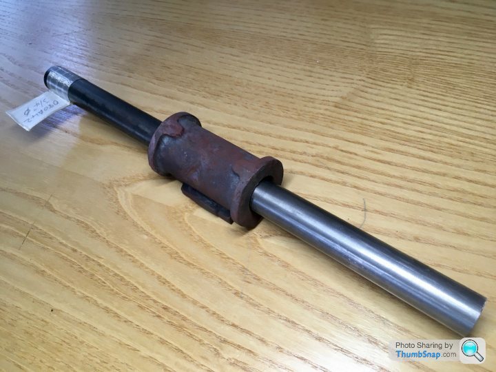
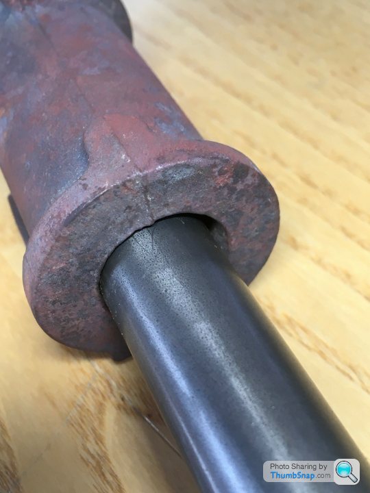
 1602 forum posts | I got a length of 1" diameter steel bar stock to make the between centres boring bar. I obviously need to face and centre drill each end, but I don't have a fixed steady (I do have a Myford travelling steady). Is there an alternative method? I assume with a fixed steady, I could set the bar in the chuck, run the fixed steady up to it and adjust, then slide it along to the end of the bar and face and drill as normal? Any other methods, or is it £100 on a fixed steady? Thanks.
|
| Ramon Wilson | 08/03/2021 13:14:49 |
 1655 forum posts 617 photos | Well a fixed steady is a good accessory to have - when you need it - which from my perspective isn't that often. You can jury rig it with a decent thick piece of ply wood bored to a good fit on the bar. Clamp or bolt the plywood to an angle plate and then to the cross slide and set as you describe. Not ideal but it would just about get you by for drilling two centre holes - and save you a hundred quid Perhaps others may have other suggestions but If I only had to do two holes that's how I'd tackle it Good luck |
| JasonB | 08/03/2021 13:29:38 |
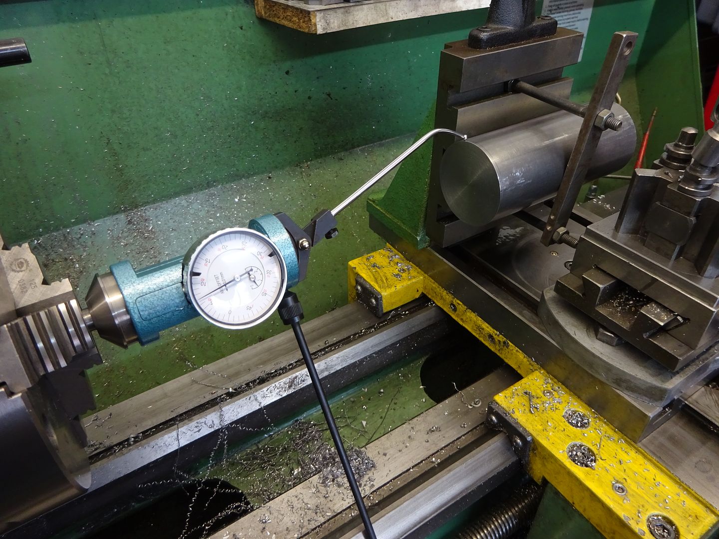
 25215 forum posts 3105 photos 1 articles | Clamp to cross slide with packing or to the Vertical slide of you have one. Flycut the end. Put DTI in lathe chuck and adjust bar's position until dti shows it's true and ctr drill with drill in spindle. I have used the wooden block method Ramon mentions in the past when I did not have a fixed steady for the Emco Strictly speaking the holes do not need to be spot on but it's handy for measuring tool projection though that can be got around by turning down a section around the toolbit hole to a known diameter Is a 1" bar going to be of use on your cylinders as it won't fit!. 3/4" would allow it to pass through the core (I think) and allow room for a few cuts & swarf
Edited By JasonB on 08/03/2021 13:31:20 |
| Metalhacker | 08/03/2021 16:40:21 |
| 82 forum posts | I am just doing the cylinders on my Twin Victoria, my first steam engine project, and I wonder how deep the 7BA tapping holes should be. I don’t want to drill through into some thing vital! Especially in the cylinder face of the steam chest. Any advice gratefully received! Andries |
| JasonB | 08/03/2021 16:45:47 |
25215 forum posts 3105 photos 1 articles | I drilled them about 6mm deep which should be plenty of thread engagement without having to bother with a plug tap, I was using a spiral flute one. End flanges nearer 4.5-5mm if you don't want to see them break through the back of the flange but not an issue if clading. The hole that comes closest to doing some damage is the 3/16" exhaust one. |
| Dr_GMJN | 08/03/2021 16:55:30 |
1602 forum posts | Posted by JasonB on 08/03/2021 16:45:47:
I drilled them about 6mm deep which should be plenty of thread engagement without having to bother with a plug tap, I was using a spiral flute one. End flanges nearer 4.5-5mm if you don't want to see them break through the back of the flange but not an issue if clading. The hole that comes closest to doing some damage is the 3/16" exhaust one. It says in the Princess Royal write-up that breaking through from the feet fixing drillings into the cylinder, is likely, but not much of an issue if you do. I suppose if the holes are small and there are no burrs, it's all sealed anyway. Having said that, I wonder if the feet holes are orientated such that they would miss the piston packing rings though? If the packing goes over a hole it might damage it. |
| Dr_GMJN | 08/03/2021 16:58:42 |
1602 forum posts | Posted by JasonB on 08/03/2021 13:29:38:
Clamp to cross slide with packing or to the Vertical slide of you have one. Flycut the end. Put DTI in lathe chuck and adjust bar's position until dti shows it's true and ctr drill with drill in spindle. I have used the wooden block method Ramon mentions in the past when I did not have a fixed steady for the Emco Strictly speaking the holes do not need to be spot on but it's handy for measuring tool projection though that can be got around by turning down a section around the toolbit hole to a known diameter Is a 1" bar going to be of use on your cylinders as it won't fit!. 3/4" would allow it to pass through the core (I think) and allow room for a few cuts & swarf
Edited By JasonB on 08/03/2021 13:31:20
Sorry, I meant 3/4": |
| JasonB | 08/03/2021 17:01:46 |
25215 forum posts 3105 photos 1 articles | Think I would tend to keep it as solid as possible. |
| Metalhacker | 08/03/2021 19:49:39 |
| 82 forum posts | Thanks guys. My first cylinder end was about 4.5, so I will continue with that throughout. Is there some formula which gives a ratio of depth to thread diameter, ie twice or three times depth? |
| Dr_GMJN | 09/03/2021 08:16:09 |
1602 forum posts | Just looking at the beds again, and the cylinders. This might seem trivial, but: The drain cocks and operating mechanism don't seem to be defined too well in the article. Which drain cocks are good for this application? The ones I used on the 10V are pretty stiff, and the handle shape wouldn't lend itself to being drilled for linkages. Reason I ask at this stage is I'd like to do all the drilling of the beds while they're square, rather than drilling on the draw angle later. If an operating spindle or rod needs a hole, and a boss, I'd like to plan for it now. Ramon - I notice you've got a nicely engineered system - but I can't see which drain cocks you used. Could you elaborate please?
|
| JasonB | 09/03/2021 08:49:37 |
25215 forum posts 3105 photos 1 articles | The straight ones that most of the other ME suppliers sell come with a flat lever that is drilled with a few holes so easily linked together and they also have a pipe union on the other end. The alternative would be to plumb the two drain holes into one 1/4 turn valve either centrally mounted under cylinder or hidden in the base |
| Ron Laden | 09/03/2021 09:15:21 |
 2320 forum posts 452 photos | I know nothing about this engine but looking at the cylinder couldn't that be set up in a 4 jaw with spacers to clear the end flanges if needed and then bored with a standard boring bar. I am probably missing something |
| Dr_GMJN | 09/03/2021 09:17:10 |
1602 forum posts | Posted by Ron Laden on 09/03/2021 09:15:21:
I know nothing about this engine but looking at the cylinder couldn't that be set up in a 4 jaw with spacers to clear the end flanges if needed and then bored with a standard boring bar. I am probably missing something I think you can, but the boring bar would have to be quite long, and the one I've got would be getting a bit flexible at that extension. Plus its another technique for me to have a go at. |
| Steve Withnell | 09/03/2021 14:41:58 |
 858 forum posts 215 photos | I've a ton of pictures I took whilst building my Victoria. I took it quite away beyond the 'kit' Stuart supplied in the end.
Most are here in the blog I ran at the time: Some the posts on this site too - ME Forum Post
Steve Edited By Steve Withnell on 09/03/2021 14:43:22 Edited By Steve Withnell on 09/03/2021 14:44:09 Edited By Steve Withnell on 09/03/2021 14:48:38 Edited By Steve Withnell on 09/03/2021 14:58:15 |
| Dr_GMJN | 09/03/2021 20:22:45 |
1602 forum posts | Posted by Steve Withnell on 09/03/2021 14:41:58:
I've a ton of pictures I took whilst building my Victoria. I took it quite away beyond the 'kit' Stuart supplied in the end.
Most are here in the blog I ran at the time: Some the posts on this site too - ME Forum Post
Steve Edited By Steve Withnell on 09/03/2021 14:43:22 Edited By Steve Withnell on 09/03/2021 14:44:09 Edited By Steve Withnell on 09/03/2021 14:48:38 Edited By Steve Withnell on 09/03/2021 14:58:15
Thanks - really nice and runs beautifully. |
| Dr_GMJN | 12/03/2021 12:54:39 |
1602 forum posts | I need to get some additional reamers - 1/4", 7/16" and 3/8". I can get them from ARC (as hand reamers) no problem, just wondering if there are any benefits or disadvantages to getting imperial/metric equivalents in terms of availability of the bar that ultimately goes through the holes? I thought I read somewhere that some were unavailable.# The 3/8" hole isn't a running fit, I think its for the crank webs, that require spigots machining to fit on the crankshaft. I might be better boring these holes - assuming my boring bar will fit? Thanks. |
| JasonB | 12/03/2021 13:03:43 |
25215 forum posts 3105 photos 1 articles | I'd bore the bearings and crank that way you can fine tune the fit, For example you want the flywheel bore a slightly tighter fit than the bearings so unless you are going to invest in 0.001" increment reamers you won't get it with a single nominal size one. 1/4" is easier done with a reamer. As for metric/imperial it really depends on what you are thinking of making in the future, imperial designs are often best done with imperial stock. |
| Dr_GMJN | 12/03/2021 15:08:28 |
1602 forum posts | Posted by JasonB on 12/03/2021 13:03:43:
I'd bore the bearings and crank that way you can fine tune the fit, For example you want the flywheel bore a slightly tighter fit than the bearings so unless you are going to invest in 0.001" increment reamers you won't get it with a single nominal size one. 1/4" is easier done with a reamer. As for metric/imperial it really depends on what you are thinking of making in the future, imperial designs are often best done with imperial stock. I think it said that the bearings were best reamed, to get a perfectly matched centre height from the mounting face (or something like that). I don't think the flywheel is specified as reamed, so that's ok. On the subject of the flywheels, the use of a double key, one of them stepped, and the riveted together rims seems pretty elaborate. Couldn't just one key be used, and the rims screwed together with CSK screws, and the slots filled? It's all machined flush in the end anyway. Presumably the key configuration is to replicate the real thing, but I cant figure out why you'd use rivets rather than screws, especially since the rims are Araldited together anyway, so it's not like they're going to move relative to each other. |
| JasonB | 12/03/2021 16:21:30 |
25215 forum posts 3105 photos 1 articles | With a chance that the drill could wander and the reamer just follow the drilled hole I would say there is more risk of different heights when reaming, Boring will true up any wayward drilled holes and provided you have the bottom of the casting against a fixed stop like the vice's fixed jaw then heights should come out the same. Double tapered keys will be less likely to "tilt" the flywheel to one side which can happen with a single key if the flywheel is a bit loose on the shaft, stepped key is only if things don't line up. From your photos it looks like you have the "lightweight" flywheels so will have to go about the joining slightly differently and if you want the barring ring than that will have to be added as a separate piece. The reason rivits are suggested is that they also expand in thickness when peined over so will ensure there is no movement unlike a screw with a bit too much clearance that can fret. I would forget the Araldite on any part of the model, we now have JB Weld which will do a better job and if you put some into the holes during assembly then screws can be used, I would probably do with M3 cap heads into counterbored holes which can then be filled. Also measure OD of the screws and use a close fitting drill for the clearance holes eg 2.8mm or 2.9mm as they are often undersize.
|
| Dr_GMJN | 12/03/2021 18:41:13 |
1602 forum posts | Hmm I didn’t realise there were different types of flywheel. Id really like to incorporate the barring notches - how do you suggest do it? Thanks. |
Please login to post a reply.
Magazine Locator
Want the latest issue of Model Engineer or Model Engineers' Workshop? Use our magazine locator links to find your nearest stockist!
Sign up to our Newsletter
Sign up to our newsletter and get a free digital issue.
You can unsubscribe at anytime. View our privacy policy at www.mortons.co.uk/privacy
Latest Forum Posts
- *Oct 2023: FORUM MIGRATION TIMELINE*
05/10/2023 07:57:11 - Making ER11 collet chuck
05/10/2023 07:56:24 - What did you do today? 2023
05/10/2023 07:25:01 - Orrery
05/10/2023 06:00:41 - Wera hand-tools
05/10/2023 05:47:07 - New member
05/10/2023 04:40:11 - Problems with external pot on at1 vfd
05/10/2023 00:06:32 - Drain plug
04/10/2023 23:36:17 - digi phase converter for 10 machines.....
04/10/2023 23:13:48 - Winter Storage Of Locomotives
04/10/2023 21:02:11 - More Latest Posts...
- View All Topics
Support Our Partners


Shopping Partners
Subscription Offer

Latest "For Sale" Ads
- Reeves** - Rebuilt Royal Scot by Martin Evans
by John Broughton
£300.00 - BRITANNIA 5" GAUGE James Perrier
by Jon Seabright 1
£2,500.00 - Drill Grinder - for restoration
by Nigel Graham 2
£0.00 - WARCO WM18 MILLING MACHINE
by Alex Chudley
£1,200.00 - MYFORD SUPER 7 LATHE
by Alex Chudley
£2,000.00 - More "For Sale" Ads...
Latest "Wanted" Ads
- D1-3 backplate
by Michael Horley
Price Not Specified - fixed steady for a Colchester bantam mark1 800
by George Jervis
Price Not Specified - lbsc pansy
by JACK SIDEBOTHAM
Price Not Specified - Pratt Burnerd multifit chuck key.
by Tim Riome
Price Not Specified - BANDSAW BLADE WELDER
by HUGH
Price Not Specified - More "Wanted" Ads...
Get In Touch!
Do you want to contact the Model Engineer and Model Engineers' Workshop team?
You can contact us by phone, mail or email about the magazines including becoming a contributor, submitting reader's letters or making queries about articles. You can also get in touch about this website, advertising or other general issues.
Click THIS LINK for full contact details.
For subscription issues please see THIS LINK.
Digital Back Issues


Donate

 Register
 Log-in
Model Engineer Magazine
- Percival Marshall
- M.E. History
- LittleLEC
- M.E. Clock

ME Workshop
- An Adcock
- & Shipley
- Horizontal
- Mill

Subscribe Now
- Great savings
- Delivered to your door

Pre-order your copy!
- Delivered to your doorstep!
- Free UK delivery!
All Forum Topics > Work In Progress and completed items > Stuart Twin Victoria (Princess Royal) Mill Engine