Forum sponsored by:

New technology in Model Engineers Workshop
The way forward.
| Gordon W | 09/06/2011 17:10:27 |
| 2011 forum posts | I don't know much about resins, but a few years ago I bought quite a lot for a job, and found a company selling re-made (?) resin, considerably cheaper than new, might well do for this sort of job. Can't remember the co. tho. |
| John McNamara | 12/06/2011 17:14:55 |
 1377 forum posts 133 photos | Hi All
Update on the Epoxy Worden
The endplates are finished… see attached photos.
A nice set of photos and yes it all worked…..
However all wrong! Well the method was.
It is easy to fall into the trap of thinking traditionally when you should be thinking “how can I improve the process using new technology.
In this case I cast the part and then machined it in the same old way as I would have with cast iron.
I then separately bored the right and left table pivot holes first, they are different one 25mm the other 20mm; as I wanted to bore all the other holes together that created an alignment problem. In the end I made a stepped locating dowel to align those holes while boring. So after setting out, then jigging up on the mill to hold them precisely, I was ready to bore. In the end I used a drill to open up the holes meaning that the location of the holes will not be exact. Jig boring the holes one by one would have been more accurate while taking a lot more time. However the error is small. Drilling them together does guarantee the holes are precisely located opposite each other a primary requirement. I ran very slowly at 75rpm with a feed of .0025” the holes did not wander, I takes a while so I set the auto stop. so I did not have to watch.
To align the Y axis rails I clamped them to two cylindrical squares, self made from 50mm x 5mm tube the large hole in the centre allows plenty of latitude when positioning ....Very handy .
So what is wrong with all that...... the time taken.
A far quicker method would have been to make up a small plate for the base of the mould using a small piece of light steel or aluminium for accuracy. All that was needed was to mark precisely drill and attach four accurately turned locating pins; and then pace the inserts pre bored on the lathe over the locating pins. There is no need to allow for shrinkage there is none with epoxy.
No further machining would have been needed the holes would be exactly positioned.
A lesson learnt
Next job is the 4 shafts and the four rail mounting blocks.
Cheers
John
Y axis aligned level with bed Zero both ends in indicator (Also transversely)
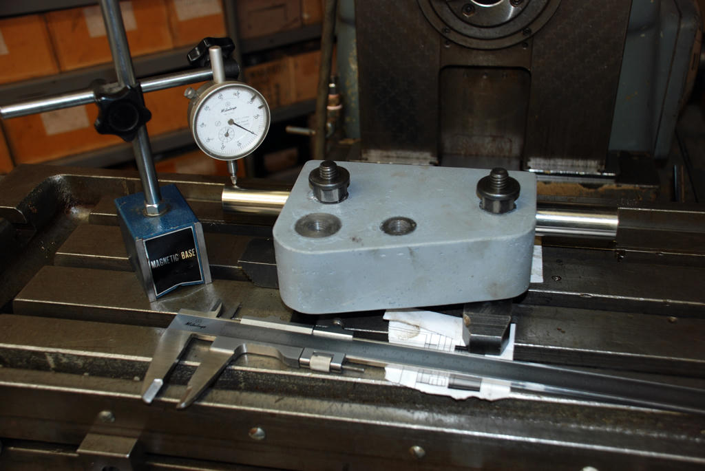 Main pivot bearing Bored
 Set up to be gang drilled
Y axis bearing aligned to cylindrical squares.
 Stepped dowel to align main bearing
 |
| Richard Parsons | 13/06/2011 13:35:14 |
 645 forum posts 33 photos | John - This is a very interesting and useful series of posts. I have no plans (as yet) to try the technique yet. However long ago I used to make chess sets from materials supplied by Strand Glass – Brentford (Usual disclaimer) with French chalk as filler. One trick I learned was to cool the resins down in the ‘fridge (in fact I cooled everything). This slowed down the setting time and helped to get more air out of the moulds and the mix. Subsequently I have had a thought about vacuum de-gassing. I used to have some ‘space bags’. You put your stuff into them and sucked out the air with a Vacuum Cleaner. Blankets, duvets etc went as solid as a rock and about half the size. The problems, as usual over here, are the Hungarians. They will overlord/overfill/over stress anything! To open them they do not undo the seal they just cut it open! –More forints up your shirt- Also I need to rebuild my vacuum cleaners, Hungarians again they can burn a new vacuum cleaner out in 30 minutes by chattering to each other with their hands over the suction pipe to stop any air getting in and cooling the motor. If you combine the cold mixing method and put the filled mould into a ‘space bag’ –with some guards to stop the bag flexing down onto the mould-. You then suck out the air and leave it to set, it should do the trick. |
| John McNamara | 20/06/2011 16:16:48 |
1377 forum posts 133 photos | Thank You Richard Parsons for your words of support
I did not have any problem with setting times or exothermic heat with this project With 15% only of epoxy Megapoxy H has a fairly slow cure the balance being aggregate and sand, the mass of the fillers was sufficient to absorb the heat. From reading other people’s papers however you are correct it can be a problem particularly with larger castings, the Worden castings are thin sections able to dissipate the heat. If I make a bigger object it will be done in layers firmly tamping each as the filling progresses.
Interesting how you mention space bags; If you look around you tube… from memory for carbon fibre processing; you will find a number of videos showing glass fibre matting being placed between two permeable sheets that are then placed in what are effectively your space bags and evacuated to high vacuum They are supported by a mould. Once the air has been removed epoxy resin is introduced into one side of the permeable membrane, it flows through the mould (The matting) and some is lost out the other side. After closing and heat curing the mould the bags and membranes are stripped away leaving the part. They were making parts for commercial aircraft.
When you mention Hungarian I think of reverse polish notation…Bar humbug!
The biggest problem for the method developed so far is the stiffness of the mix more than air bubbles. However as I am a firm believer in paint the blemishes have been patched. They have not affected the structural integrity.
Cheers
John
|
| John McNamara | 20/06/2011 16:18:04 |
1377 forum posts 133 photos |
Hi All
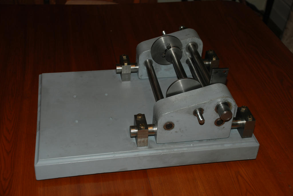
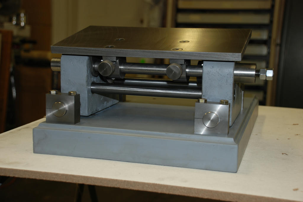
It’s been a while since I updated the Mineral Casting method Worden tool and cutter grinder. The good news it has proven without doubt the kind of rigidity you can expect from this method of construction. The movement of the table carriage feels more like a lathe saddle than a grinder there is no perceptible movement. When the tool is finished I will document it formally.
The bill of materials: So far all from the scrap bin except for a Litre and a bit of epoxy, Cost about 30 dollars and a bag of aggregate and a bag of sand; total cost $14 from a garden supply. It looks like the only steel to be purchased will be the Table piece but I am still rummaging, also some M8 hex cap screws to replace the machine screws currently holding the bearing rail blocks.
To this point The x axis table movement is complete; it is not obvious from the photos but the front top bar that will carry the table pivot brackets can move laterally a distance of 25mm left or right a total of 50mm. The table itself can also move independently upon releasing the two lock nuts (See previous photos). At the opposite end the shaft is bored for a long spring to preload the feed screw. Similar to the way the Quorn feed is arranged although the Quorn does not have a bored shaft the screw bears against the shaft.
I am considering adding stops and a lever for quick action on saws and cutters. In particular the draw full inch bore milling cutters I have not been able to sharpen. I plan to sit them on the table in the horisontal position on a locating arbor, and index them against a spring stop finger as is the norm. A lever action would speed the process. There should be no chatter the machine is rock solid.
The y axis in feed not yet built will make precise adjustment of the depth of cut very easy. This is where this design is quite different from the original the entire table can be precisely located in the X and y plane. Attachments can be simplified in some cases avoiding the need for a feed mechanism.
The turned boss bolted to the right hand casting with a projecting screw is the x axis control. The screw itself is fixed within the boss, the movement being obtained by an M12 threaded hole in the end of the shaft that engaged the threaded shaft. This keeps the mechanism completely internal and away from grinding dust.
The arm pointing upwards from the top shaft abutting the left hand casting is to transfer the angle of the table to the table angle pointer that will be fitted to the outside of the left casting…You can see it in the photos of the earlier posts. This part is not finished the two holes and a section of it will be cut off. It is just a convenient piece of scrap that was to hand. Because this piece needs to be exactly in line with the top of the table support brackets I will not trim it until the brackets are done.
The table lift cams are complete as well as a secure brake to hold them in position. The plain turned M12 nut in the photo will have a lever with a bored hole that can clamp on the turned nut. This will provide adjustment of the clamped position.
Engaging that nut pulls the cam bar to the right, the cam itself sits against a shoulder to stop it sliding along the bar the other side of the cam is forced against a 45mm hollowed out disk attached to the casting, effectively forming a small disk brake. A half turn on the M12 nut and I was unable to move the cams.
The next step is the table and brackets. As no one has posted the dimensions of a warden table I will just make it as is if anyone builds the machine by this method they will have to adapt any attachments they may build to fit this table as the position of the radius clamping Arc and the centre point is unlikely to fit.
The motor mount is still a work in progress; I think it should be possible to rotate the motor. Even as much as 90 degrees? Any comments would be welcome.
There was some discussion re Epoxy a few posts ago, Has anyone found a reasonably priced source of supply for the UK?
There are a few photos below the captions should be fairly self explanatory.
Cheers
John
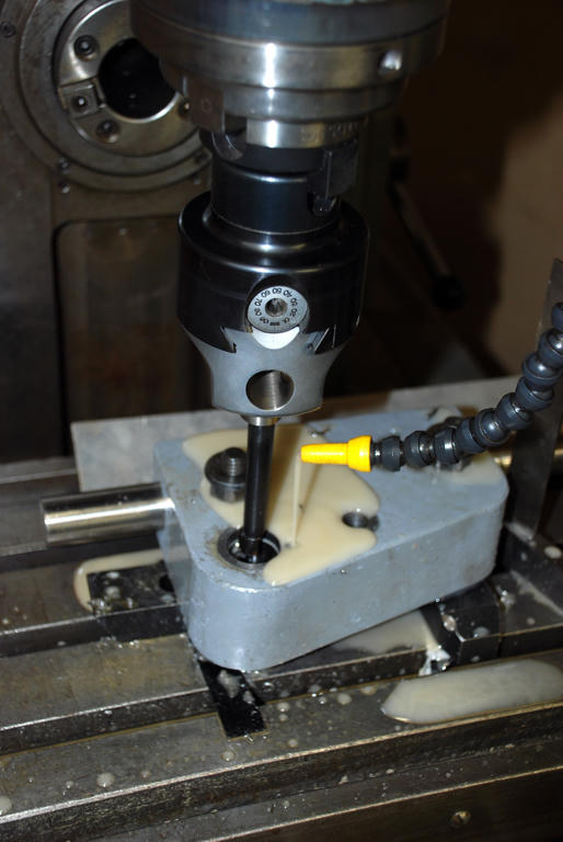
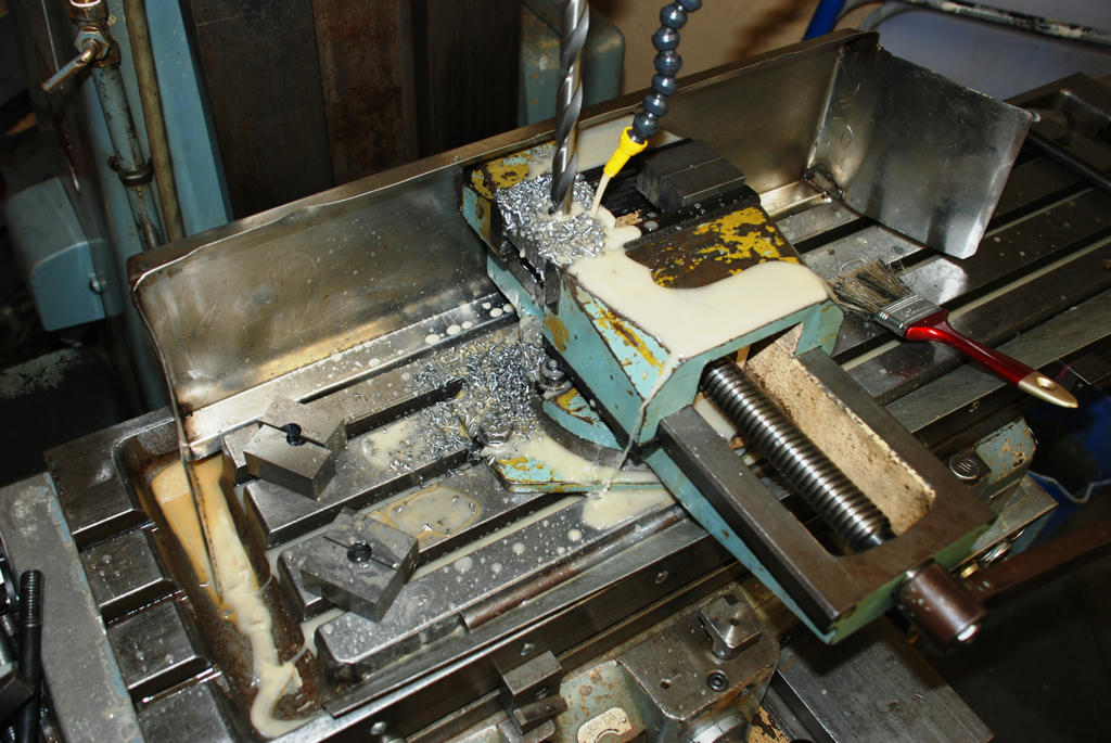
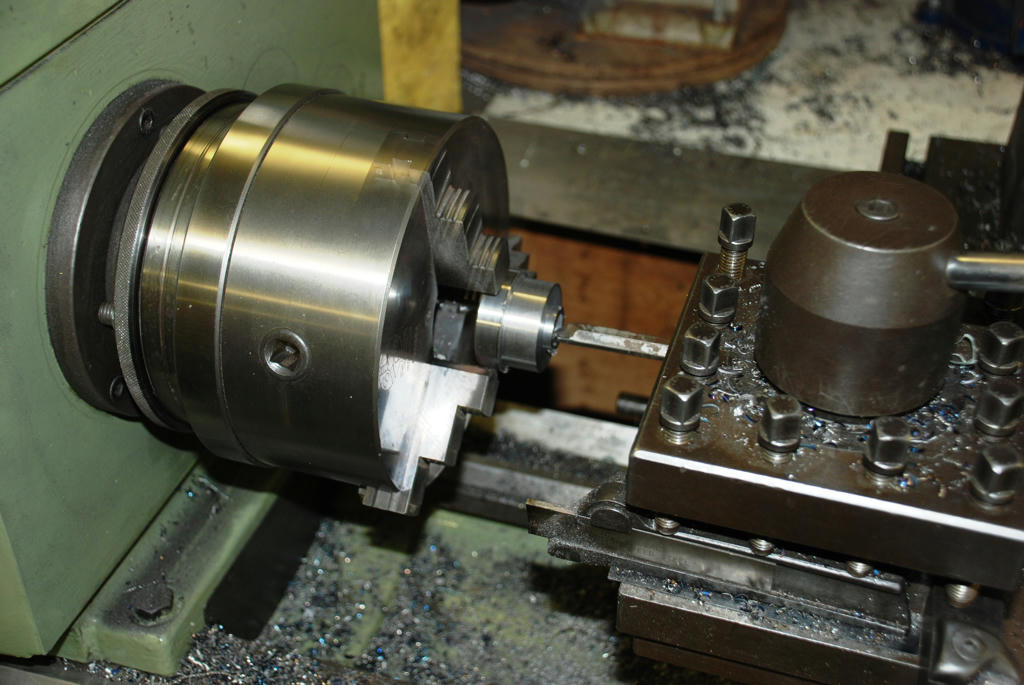
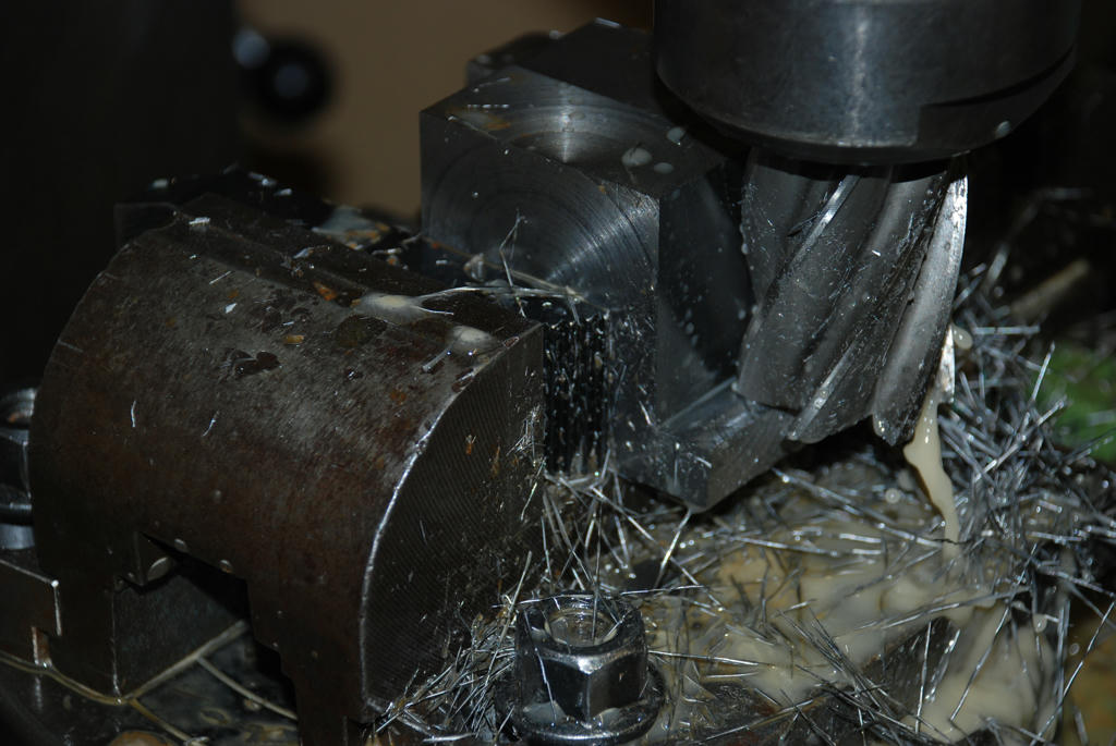
Nicking the two halves of the bearing blocks in the centre to start the hole in the centre
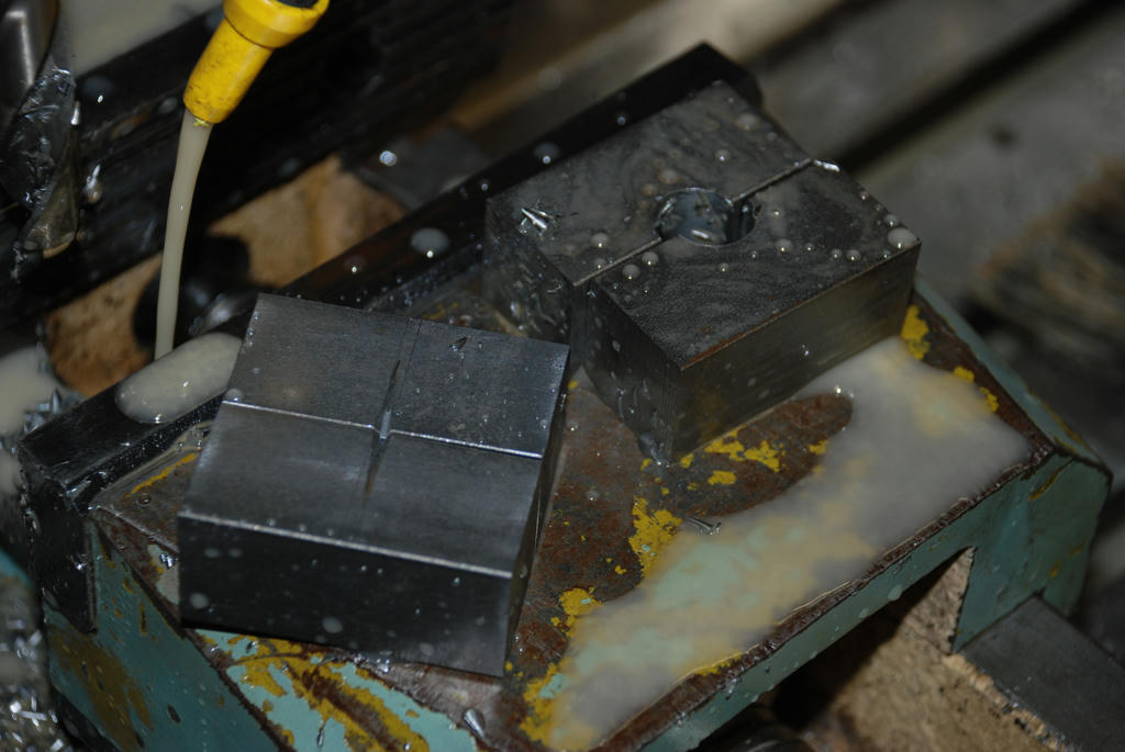 Starter drilling the 25mm holes
 Continued next post
|
| John McNamara | 20/06/2011 16:37:31 |
1377 forum posts 133 photos |
Continued from previous post
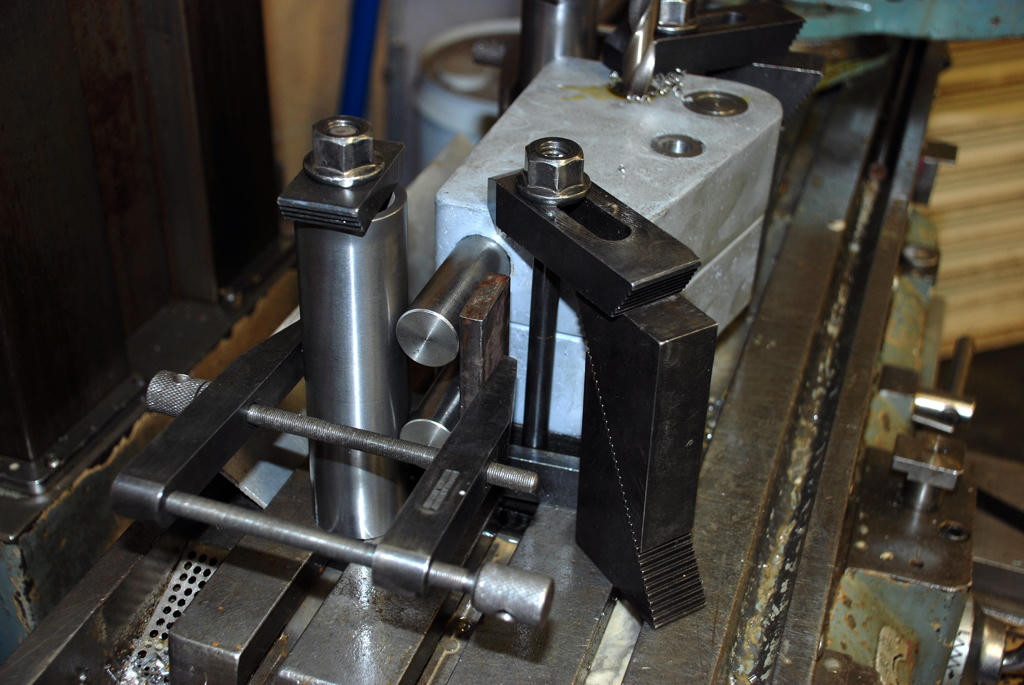
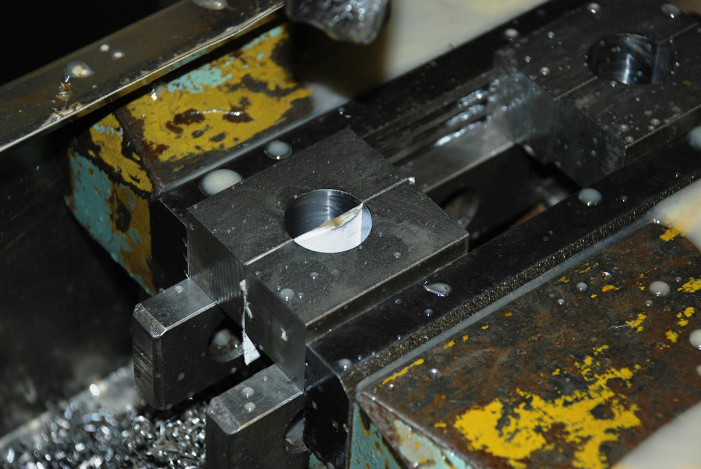
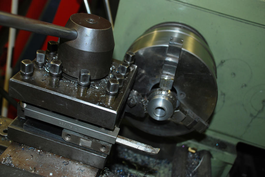
Paper inserted to create a gap for clamping.
 Gang Drilling table cams
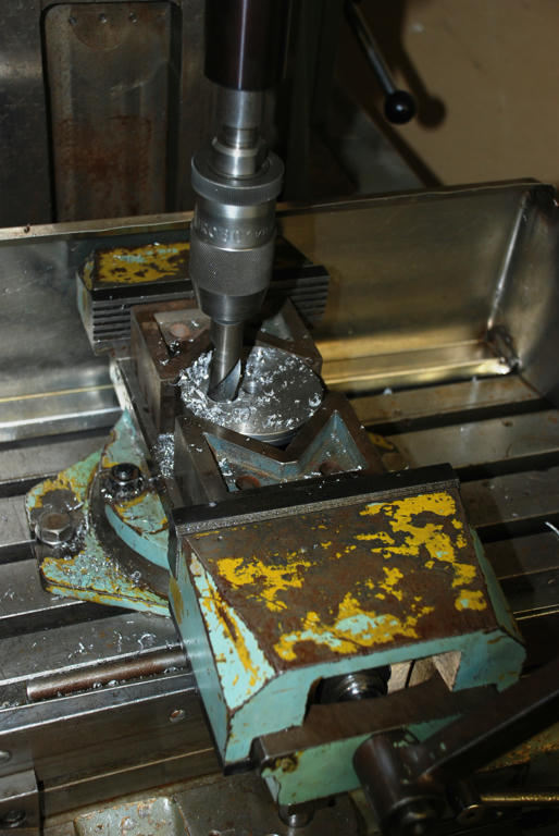 Precision boring table cams
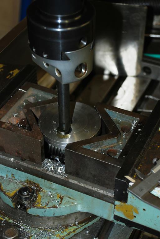 Boring cam boss
 Parting Cam Boss
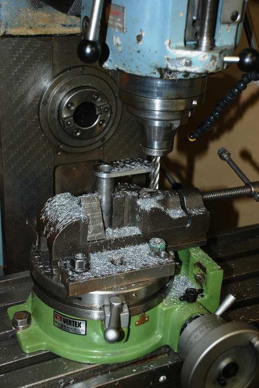
 Milling table angle arm on rotary table
 Continued next post
Edited By John McNamara on 20/06/2011 16:48:28 Edited By John McNamara on 20/06/2011 16:49:20 |
| John McNamara | 20/06/2011 16:52:37 |
1377 forum posts 133 photos |
Continued from previous post
Left rear view
 Left Front View
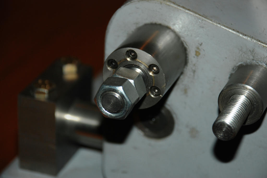
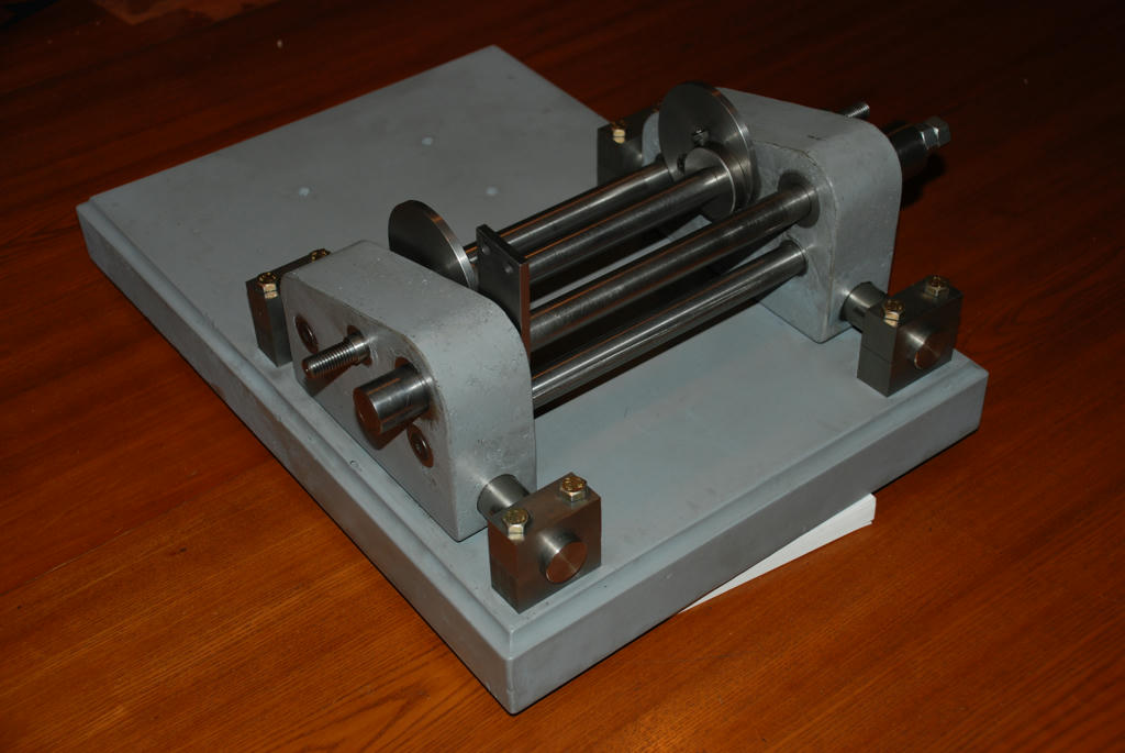 Right front view
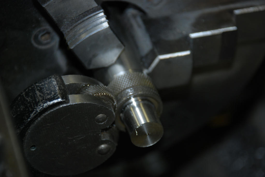
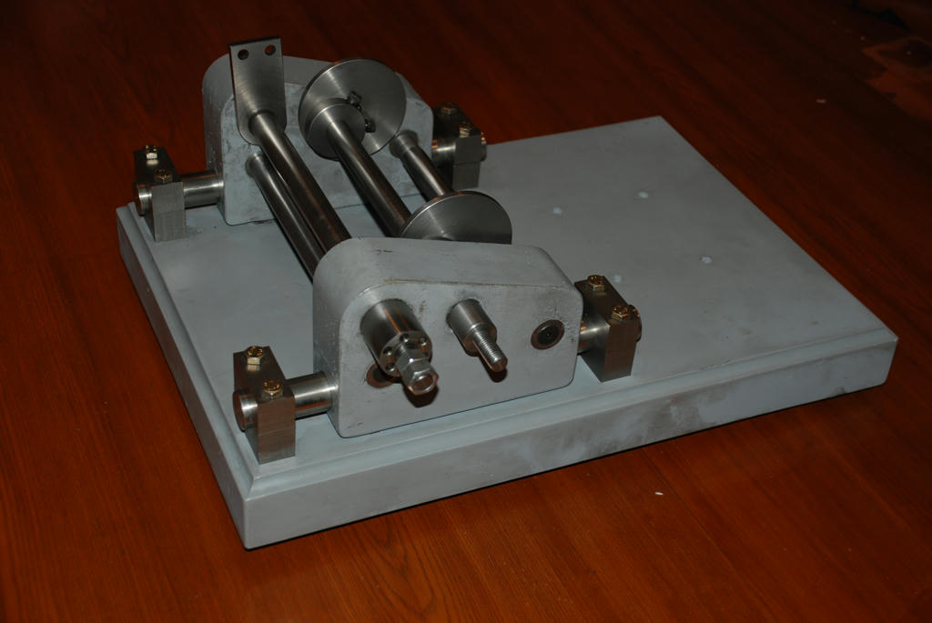 Feed and clamp shaft detail... Boss was bored straight through reducing collar silver brazed in then faced off in the lathe. The M3 set screws attach to the steel casting insert
 Cheers
John McNamara
Edited By John McNamara on 20/06/2011 16:59:47 |
| John McNamara | 26/06/2011 16:53:43 |
1377 forum posts 133 photos | Hi All
A quick Update… The Table support brackets and table made.... Yes I found a nice bit of plate in the scrap pile. Rather happy it had been Blanchard ground, you can see the marks, After a bit of cutting it was ready, it is 13.5mm thick, a little thicker than the 12mm I had planned on using. The photos show the process I used. The last two are exciting…. I just placed the cutters on the table for inspiration. The motor will have to be rotatable. This will be more versatile for working on various shapes of cutters.
Next, the Y axis feed and the motor base after that. The plan is to do all other knobs and the graduations at the same time at the end.
Cheers
John First milling cut table support brackets I squared them on the lathe in the 4 jaw
 Cutting the circular Arc on the table support brackets
The part is centred by the bore hole for the support shaft, on a centre mounted
on the rotary table. Clamp is pressing down. 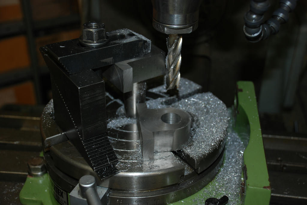 Table slide locking knobs. In one chuck setting
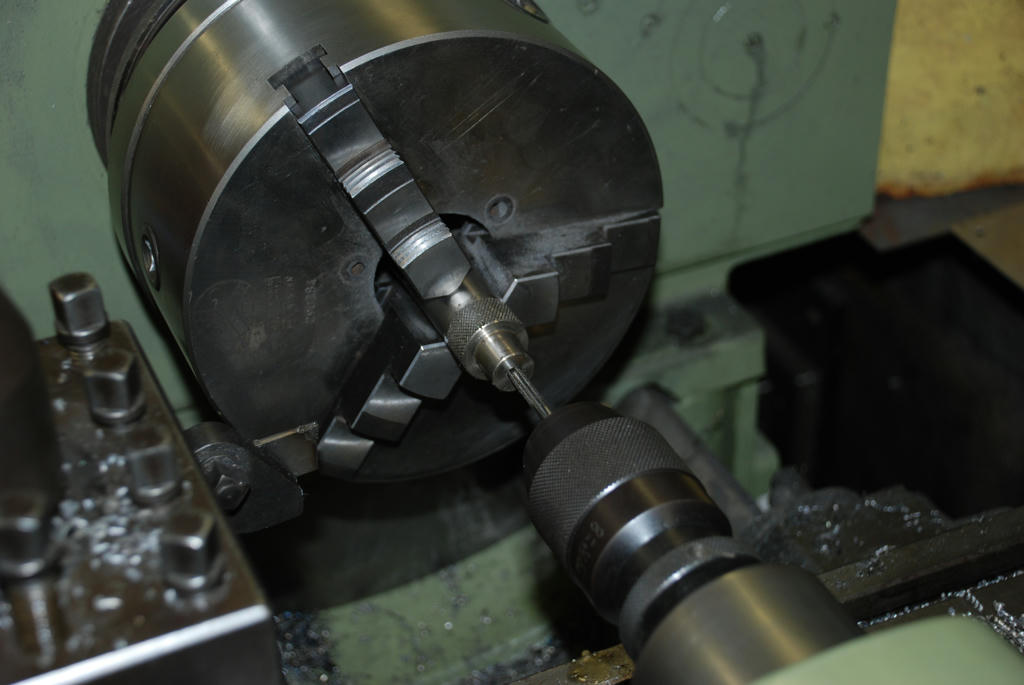
25mm shaft chucked
Faced
Thin section turned watch out for the SS swarf it cuts (the lathe was stopped but even clearing it away it got me.)
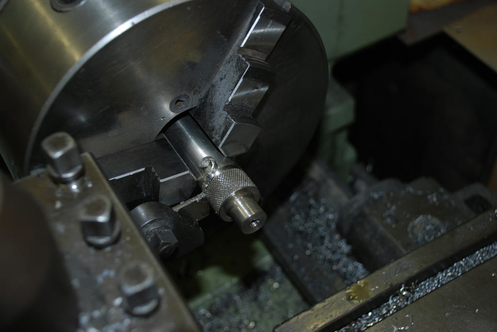
Turn the area to be knurled taking a couple of thou of to get a true centering. and a clean start for ther rolls to bite in
Knurled.. Heavy pressure .003 feed (Or the lowest feed you have) 3 passes (Do not go off the end just to the 3/4 point on the rolls) increase the pressure a little each feed.
I got a very nice diamond knurl. the material was 304 stainless it work hardens so be patient.
 Drill 20mm hole and tap I started the tap in the tailstock to get a straight start
 put a small 45 degree chamfer on the end edge and the inside knurl edge Not shown Part off knob Dont dither with the tool rubbing, it will work harden, enough pressure to keep it cutting. If you want to stop pull well back. Lots of oil
 The final step is to put the knob back in the chuck face off the parted end and do a small 45 degree chamfer on the edge. Continued next thread |
| John McNamara | 26/06/2011 17:00:20 |
1377 forum posts 133 photos | From previous thread
Table installed (It will be milled and engraved later)
 Rear view
Possible cutter sharpening
Thinking of larger cutters the motor will need to be rotatable 90 degrees Cheers John |
| Stub Mandrel | 28/06/2011 21:11:27 |
 4318 forum posts 291 photos 1 articles | Phew this has been a bit of a marathon read. All fascinating, and I must say my interest is piqued in engineering epoxy. My 'surface plate' is a slab of epoxy granite worktop, about 18"x12" and appears to be both accurate and durable. The price was just the cost of the cheap angle grinder I used to cut it off a larger piece. It cut easily with a diamond wheel, and I got a bit blase... until teh smoke started. Oh well, nice set of bevel wheels for future project! My 'worden-a-like' grinder is semi-finished but working. Its based around linear bearings from an old dot-matrix printer, and the workholder is made so it can swap with a mini-lathe topslide. The motor is a cheap grinder remounted on a length of alloy scaffold pole (found in the road) with a diamond wheel attached. The wheel adpator was turned in place with the existing centres on the grinder spindle between centres - you can't see or feel any wobble in the diamond wheel stopped or spinning - cheap grinder, but decent bearings. It can be moved up and down or rotated, but not with any degree of fine feed. Most workholding is done using ER25 collets in a spindle. Wait for it.. the base is 1 1/4" thick plywood and the table and itssupports are 3mm or 1/8" mild steel plate found in the garage that became my workshop. The table moves on tworails made of angle iron! Cuts are applied by moving the table left/right on the printer slides (phosphor bronze bearings on hard steel rod) or advancing the work holder on a scombined swivel/dovetail slide base from cast iron. It all looks VERY agrcultural and the motor get hot if run more than about 20-30 minutes, but I'm quite happy with the results sharpening a range of endmills. I've since wondered about mounting a smallish grinding wheel on the X2 mill to make a surface grinder. Neil |
| John McNamara | 30/06/2011 15:48:09 |
1377 forum posts 133 photos | Hi Stub Mandrel Glad to hear you are piqued….Re Epoxy Cheers John |
| John McNamara | 30/06/2011 15:49:11 |
1377 forum posts 133 photos | Hi All
I noticed a mention on another post in the MEW forum “Using the technology” of externally linked images compared to images posted on MEW I am not sure if this site does but many sites cut the resolution down before storing the files to save space. I use externally hosted file images stored at the full resolution of the camera (10.2 megapixels). In case you are not aware; if you double click the image you can zoom in to see more detail. However the image is not full resolution
The actual images are posted here:
Cheers John Edited By John McNamara on 30/06/2011 15:55:21 |
| Richard Parsons | 01/07/2011 18:03:00 |
645 forum posts 33 photos | John McNamara
Thanks for your reverse polish notation - You've met them! I have PM-ed you so your 'My Messages are 'flashing'
Regards
Dick Parsons |
| John McNamara | 05/07/2011 12:58:16 |
1377 forum posts 133 photos | Hi All Just an update…. I am bogged down with the motor design. And feel a little guilty for not posting an update to the project. The plan is to make the motor rotatable; the trouble with that is a standard frame size motor is too big to comfortably fit within the base of the machine. Making the motor rotatable means that a spindle is required in addition to the motor (the grinding wheels for this design being around 100mm in diameter) that is a lot smaller than a typical induction motor. The spindle itself is not a problem and it gets over the problem of end play of the motor shaft. I know you can pack the motor bearings and get some sort of pre load. But conventional Conrad ball bearings as used in nearly every motor are not nearly as stiff as Angular contact bearings properly preloaded in a spindle. Back to the motor…I came unstuck! the plan was to use a Universal motor (It is almost fully enclosed so dust will not be a problem) and I had one in stock. Well I thought I did. It is a FRAMCO (Fractional Horsepower Motors UK) 1/3 hp the right size and all it needed was a new bearing. So it was taken apart and the bearing replaced. I noticed the comutator was a little grooved, no problem…. into the lathe it went and after a light skim, the copper was shiny bright. After cleaning out the groves between the contacts it was ready to reassemble. No I did not check it for shorts, wrong move there…. having put it back together and powering it up you guessed it a little puff of smoke and a blown fuse; so much for that Idea. The comutator is shorted. A new motor will have to be sourced. Hopefully this week so I can get on with finishing the project. Cheers John Edited By John McNamara on 05/07/2011 12:59:21 |
| Ian S C | 06/07/2011 11:14:27 |
 7468 forum posts 230 photos | A few years ago (quite a few), I would have suggested a rebuild, But not today, I imagine its similar in the UK, you would buy two motors for the price of a rewound armature. Ian S C |
| John McNamara | 12/07/2011 13:10:16 |
1377 forum posts 133 photos | Hi All
An update A new motor was ordered today, it arrives in a couple of days. Now I know the size it is back to work and the project can continue. Once it arrives (The supplier is in another state South Australia) and is tested; I will post the source. It is an induction motor 1/6 hp 120watt 2800rpm 120mm diameter 190mm long including the shaft Frame size 56 continuous running and IP56 fan cooled sealed construction. Also today I spoke to the Megapoxy representative in Melbourne. He suggested that the best contact for them in Europe is: Tassos Anastasopoulos [email protected] As I understand it this is their main distribution hub. I would like to point out that I am only a customer of this company and have no other connection to them, having said that they have given excellent service. Re missing images: The servers are being upgraded at Mediafire. See the following mesage I received.
""Thank you for contacting MediaFire. While our development team is performing maintenance on some of our image servers, image previews will be unavailable for some images. The images can still be downloaded and shared, but the web-based preview will not work until this maintenance is complete. Currently the time estimate I have been given is several days, although that is subject to change. We apologize for the inconvenience that this is causing to both you and your clients. ""
Lets hope that is sooner rather than later.
Cheers John |
| Ian S C | 12/07/2011 13:28:38 |
7468 forum posts 230 photos | John, are you sure that 120W is enough, I run my Super Adept on a 180W induction motor, and anything over an inch in dia takes a lot of patience to say the least. My small bench grinder is 380W, 2800rpm, running 5" wheels, I'd have thought 300W might be nearer, but size is the thing. Ian S C |
| John McNamara | 13/07/2011 06:42:33 |
1377 forum posts 133 photos | Hi Ian
Gee you got me thinking. The local hardware has small 120watt bench grinders. However you may be right. Anyway I changed my order to a bigger frame size. .55kw I guess that will be overkill. If I cannot get the small size I wanted I might as well get plenty of power. The minus is it has added 55mm to the length of the motor, meaning a longer ball bearing wheel spindle will be required. The new design will include the ability to rotate the motor 90 degrees. This should make the design more flexible. It might even be possible to use it as a cylindrical grinder within the 50mm table travel. The motor was sourced here: I have no connection with this company I found them on the net. However I received friendly and helpful service so am happy to recommend them. Ask for Sam. Cheers John |
| Ian S C | 13/07/2011 11:22:14 |
7468 forum posts 230 photos | My little motor is a 1450rpm ie 4pole motor, so it has more torque than the 2800rpm motor. Its marked IBM, I think it came out of a cash register. Ian S C |
| Gordon W | 13/07/2011 13:53:34 |
| 2011 forum posts | I've been reading this post with interest, and may well have missed some parts. What I would like to know is what tooling was used in the construction, ie. drilling, boring etc. Carbide? I imagine the resin mix as being quite difficult to machine. Apologies if this has been covered. |
Please login to post a reply.
Magazine Locator
Want the latest issue of Model Engineer or Model Engineers' Workshop? Use our magazine locator links to find your nearest stockist!
Sign up to our Newsletter
Sign up to our newsletter and get a free digital issue.
You can unsubscribe at anytime. View our privacy policy at www.mortons.co.uk/privacy
Latest Forum Posts
- *Oct 2023: FORUM MIGRATION TIMELINE*
05/10/2023 07:57:11 - Making ER11 collet chuck
05/10/2023 07:56:24 - What did you do today? 2023
05/10/2023 07:25:01 - Orrery
05/10/2023 06:00:41 - Wera hand-tools
05/10/2023 05:47:07 - New member
05/10/2023 04:40:11 - Problems with external pot on at1 vfd
05/10/2023 00:06:32 - Drain plug
04/10/2023 23:36:17 - digi phase converter for 10 machines.....
04/10/2023 23:13:48 - Winter Storage Of Locomotives
04/10/2023 21:02:11 - More Latest Posts...
- View All Topics
Support Our Partners


Shopping Partners
Subscription Offer

Latest "For Sale" Ads
- Reeves** - Rebuilt Royal Scot by Martin Evans
by John Broughton
£300.00 - BRITANNIA 5" GAUGE James Perrier
by Jon Seabright 1
£2,500.00 - Drill Grinder - for restoration
by Nigel Graham 2
£0.00 - WARCO WM18 MILLING MACHINE
by Alex Chudley
£1,200.00 - MYFORD SUPER 7 LATHE
by Alex Chudley
£2,000.00 - More "For Sale" Ads...
Latest "Wanted" Ads
- D1-3 backplate
by Michael Horley
Price Not Specified - fixed steady for a Colchester bantam mark1 800
by George Jervis
Price Not Specified - lbsc pansy
by JACK SIDEBOTHAM
Price Not Specified - Pratt Burnerd multifit chuck key.
by Tim Riome
Price Not Specified - BANDSAW BLADE WELDER
by HUGH
Price Not Specified - More "Wanted" Ads...
Get In Touch!
Do you want to contact the Model Engineer and Model Engineers' Workshop team?
You can contact us by phone, mail or email about the magazines including becoming a contributor, submitting reader's letters or making queries about articles. You can also get in touch about this website, advertising or other general issues.
Click THIS LINK for full contact details.
For subscription issues please see THIS LINK.
Digital Back Issues


Donate

 Register
 Log-in
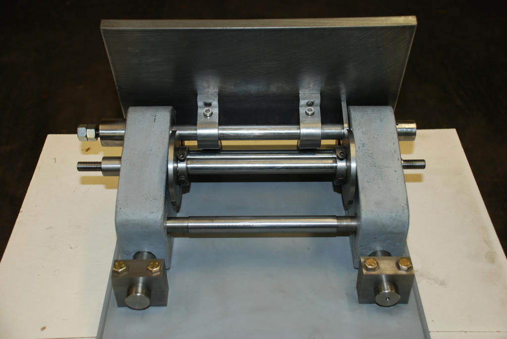
Model Engineer Magazine
- Percival Marshall
- M.E. History
- LittleLEC
- M.E. Clock

ME Workshop
- An Adcock
- & Shipley
- Horizontal
- Mill

Subscribe Now
- Great savings
- Delivered to your door

Pre-order your copy!
- Delivered to your doorstep!
- Free UK delivery!
All Forum Topics > Model Engineers' Workshop. > New technology in Model Engineers Workshop