Forum sponsored by:

Stuart Twin Victoria (Princess Royal) Mill Engine
| Zan | 09/09/2022 23:57:11 |
| 356 forum posts 25 photos | Impressive stuff doc, and it’s interesting reading your quest for high accuracy and you are a really skilled worker oozing quality, but it’s really time you purchased a decent micrometer Cheap digital callipers are great to get you started and for basic use. You are very much a cut above that level of action and with one you will find things a lot easier. I only use mine for quick’ reference and on non critical turning, otherwise out comes the quality micrometer |
| JasonB | 10/09/2022 06:51:11 |
 25215 forum posts 3105 photos 1 articles | Look in the photos he has a Mitutoyo mic for final measuring. Same make as his callipers Edited By JasonB on 10/09/2022 06:51:54 |
| Michael Gilligan | 10/09/2022 07:22:03 |
 23121 forum posts 1360 photos | … the process of ‘moderation’ nicely demonstrated. MichaelG. |
| Zan | 10/09/2022 09:10:49 |
| 356 forum posts 25 photos | Agreed, my apologies I missed that photo but why then did doc say “Got the metric step diameters spot-on (at least to the 0.01mm accuracy of the calipers)” when there’s a micrometer I wouldn’t trust my mitutoyo calliper for measuring here but would use my digital Mitutoyo……. Still impressed though!
|
| SillyOldDuffer | 10/09/2022 10:47:28 |
| 10668 forum posts 2415 photos | Posted by Zan on 10/09/2022 09:10:49:
Agreed, my apologies I missed that photo but why then did doc say “Got the metric step diameters spot-on (at least to the 0.01mm accuracy of the calipers)” when there’s a micrometer I wouldn’t trust my mitutoyo calliper for measuring here but would use my digital Mitutoyo……. Still impressed though!
One of my hobby-horses is the difficulty of getting high-accuracy measurements right. No criticism of Doc's work, which is much better than mine, but I fear he's stumbled into error by claiming an accuracy greater than that of his instrument! Although the resolution of his caliper is 0.01mm, implying an accuracy of ±0.005mm, Mitutoyo's stated accuracy is only ±0.02mm. I don't think the inaccuracy matters for what Doc is doing, but it might if several Docs were working separately to build a Princess Royal, each being responsible for various different parts to be brought together and assembled later. It doesn't matter because although Doc's slip gauge stacks aren't accurate in absolute terms, they ensure a high-level of repeatability in Doc's workshop, and I'm sure his finished engine will be wonderful. Historical diversion: I think the Princess Royal engine must be named after Queen Victoria's eldest:
Her son is more famous!
Pictures: Thomas Heinrich Voigt, Public domain, via Wikimedia Commons Dave |
| Zan | 12/09/2022 13:35:38 |
| 356 forum posts 25 photos | Doc, regarding tool bit grinding, you may like to see my post and phots of my simple grinder rest in this thread lathe carbide tool issue sorry, can’t find out how to post a link to it please contact me if you want more details
Edited By Zan on 12/09/2022 13:38:44 |
| roy entwistle | 12/09/2022 17:25:08 |
| 1716 forum posts | First impression of Queen Victoria's eldest, I thought she was holding a shotgun |
| Dr_GMJN | 16/10/2022 22:43:39 |
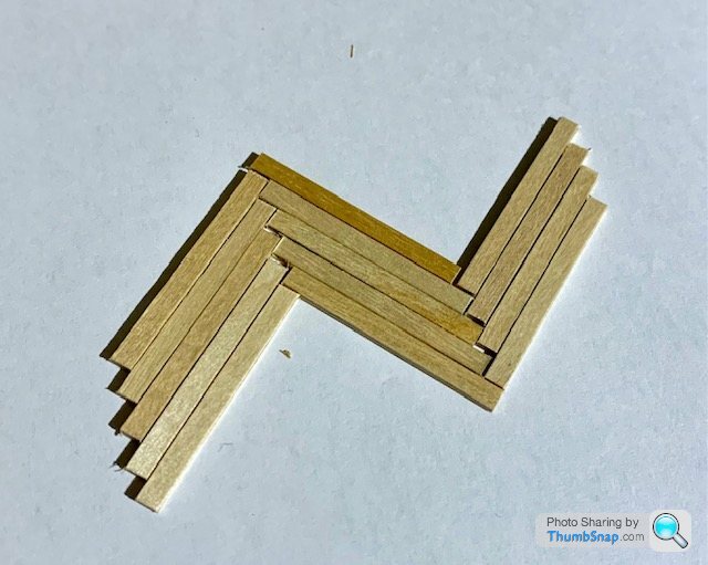
 1602 forum posts | All, I think this might have been touched upon a while back, but I can't find where: I'm wanting to start the base for the model, and to do a parquet wood effect. I need to know the approximate scale of the model to get the floor looking right. |
| JasonB | 17/10/2022 06:56:53 |
25215 forum posts 3105 photos 1 articles | I think PR was said to be about 1/18th and Goliath 1:24 and remember commenting that 3" rail height was a bit much as usual height is 3ft |
| Dr_GMJN | 17/10/2022 08:50:09 |
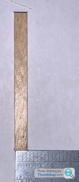
1602 forum posts | Thanks Jason. From what I found online, top rails should be a minimum of 950mm above the floor, with 1000mm being common. Of course these are modern standards. Maybe there were none back when engines like this were used, and perhaps people were shorter? Whichever scale it is, it’s only a matter of about 0.5mm difference, and since I’ve got a shed load of 4mm strips I might as well use them. I’ll have to make some kind of length trimming jig for multiple strips, and get a very sharp saw… |
| Ramon Wilson | 17/10/2022 08:53:49 |
 1655 forum posts 617 photos | Rather you than me from a patience perspective Doc but it's going to look impressive if you bring it off. I've done similar with 'decking' but with much longer pieces. Only thing I'd comment on is that the engine would be extremely unlikely to sit direct to the flooring - the flooring being brought to the engine foundations. As an aside are you aware that if you pre-coat the part with PVA and let it dry you can activate it again with a hot iron? ie place the part in position hold an iron on for a few seconds and the part is stuck - Done this a lot with 1/32 and 1/16 ply reinforcing on balsa surfaces - works well and the technique might be of use to you. Finally picked up on the Marine Engine - hope to see it through to finish this time - ha! says he! Best - R
|
| Ramon Wilson | 17/10/2022 09:34:21 |
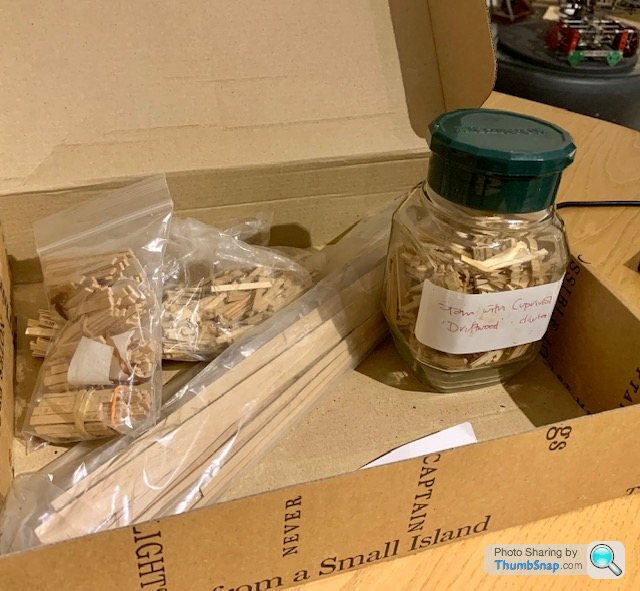
1655 forum posts 617 photos | Further to your last post Doc I just did similar for the lagging on the marine engine
Just two pieces of balsa CA'd to a slip of Conti Board and a stop to give the length.
The major guide acts as a guide for the saw which is a Zona razor saw - finest TPI they do
That gave a consistent result but if I were doing 2500 pieces I would reinforce the end of the saw guide with something.
Hope that's of use too |
| Dr_GMJN | 17/10/2022 21:27:24 |
1602 forum posts | Thanks Ramon. I wasn’t aware you could activate PVA like that. It might be good to get the whole lot layer out properly, then iron it. I know some PVAs are re-dilutable with water (Formula 560 Canopy Glue for example), whereas the outdoor stuff is obviously permanent. I always use the former for models because it gives you chance to correct things. I assumed the beds wouldn’t be placed on wood, I suppose it’s a bit of modeller’s license. I guess you could say the pieces might have butted up to the bed frames? I was going to use plain wood, but then when I inherited these chips I thought it would be good to use them, otherwise they will be scrap. I’d like to make a metal jig that holds at least 10 strips at a time. Shouldn’t be too difficult. I’m also pondering whether to make the cylinder jackets out of wood, like your marine engine. I don’t really know how to fix them though. The brass band method can to my eyes look a bit “added on later”, especially the band fasteners when they screw into the cylinder casting. Anyhow first I need to finish the bearings, the with the shaft done I can at least say the two halves can be linked, and that will be a decent step forward. Cheers.
|
| Ramon Wilson | 17/10/2022 23:09:41 |
1655 forum posts 617 photos | Hi Doc, Yes if you could 'contain' all your small pieces from moving somehow you could indeed iron through them in a large area. I've not tried it on a paper substrate however so as with trying anything new a good test piece is well worth while beforehand. I've used various PVA's over the years - my favourite (for aeromodelling) was Borden Wood glue, later renamed Humbrol Extra Bond. Both long extinct. Any of the 'TiteBond' adhesives are good PVAs but when I made the steam launch I tried the Titebond 3 (green label) water proof version. What impressed me most with using that was it's extremely quick (for PVA) grab time - now I don't use anything else. Might also be worth considering. I usually mount my engines on a foundation of MDF set on the base proper. This can be worked to represent simple concrete foundation or separate blocks if desired, it's very flat, uniform and hard enough to withstand the bolting forces and any subsequent running. It would also mean you don't need to spend time fixing tiny pieces underneath the engine which will never be seen. The wood lagging I've made for the marine engine is attached with CA to a 12 thou thick aluminium sheet lagging.. This was made from a paper template made in three parts off the cylinder block to achieve the expanded profile. I've been drilling the head and fitting small bushes tapped 12BA for the holding screws today. I'll have to pop some pics up at some stage. Best - R |
| JasonB | 18/10/2022 07:56:46 |
25215 forum posts 3105 photos 1 articles | A lot will depend on how you retain the cladding, the usual two straps and some round head screws may look a bit crude particularly if overscale for this engine. If you look at some of the larger full size engines then the brass is somewhat more detailed often having an "L" section that clips over the ends of the slats and at this size just bonding in 1/32" rivits would give a better size head than trying to use screws. Good example of it here on Simon's No4 and carried on on the next page. The Titebond I, II & III glues are Alphatic resins which are a bit different to PVA and is one of the reasons for their faster grab. Edited By JasonB on 18/10/2022 07:57:53 |
| Ramon Wilson | 18/10/2022 09:35:20 |
1655 forum posts 617 photos | Posted by JasonB on 18/10/2022 07:56:46:
The Titebond I, II & III glues are Alphatic resins which are a bit different to PVA and is one of the reasons for their faster grab. I stand corrected Jason I have always thought of it as a 'PVA'. I have not used it as previously described for a PVA glue being reactivated by a hot iron so a test would be required to see if it acts in a similar way I've stuck quite a few small strips of wood down to a substrate (usually birch ply) over the years though nothing quite like what Doc has in mind. These have mainly been decking on 'ship' models and have included black paper inserts between to simulate caulking. Adhesive has always been very thin cyano and application has to be done with care to ensure the CA does not get on to the top surface. It was always applied to the edge with the plank held in position beforehand and allowed to wick through underneath The main thing to be aware of is the positioning of initial 'key' parts as any errors soon manifest themselves into a deviation from that desired. Same with the 'planks' or parts - any error in length or width quickly becomes obvious as the differences build up. I admire Docs courage to having a go - it's a lot of pieces to fix over quite a large area and will require some quite accurate parts. Given that, I feel it would be best to cut them by 'machine' to ensure symmetry of length rather than by hand if possible. Thought also needs to be given to symmetry of the whole pattern if a border edging is to be done too. A complex task but one that will be very impressive overall if done well - which I'm sure it will be having seen work done so far
Best - R
|
| JasonB | 18/10/2022 09:56:06 |
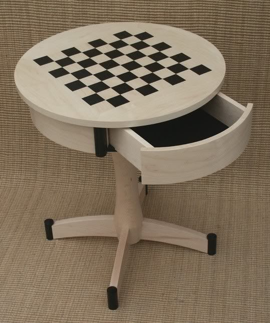
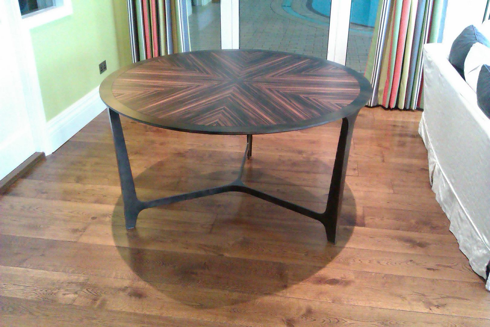
25215 forum posts 3105 photos 1 articles | Agree any deviation in length even if only small will soon start to throw the pattern off, even consistantly butting the edges and ends together equally will be a challenge. Though more of a challenge wil be to do the T&G joints to ends and edges I mostly use Titebond II for works and buy it in 1gal at a time, it also dries with less flexibility than PVA so is good for bent laminations. Their cold press glue is quite good for veneering and I usually use their PU for anything that may see the weather The curved laminations and top were done with TBII on this, they are about 40mm squares of Ebony and Maple
This was cold press 24 pieces of maccasar ebony, about 1.4m dia, frame is steel also by me
|
| roy entwistle | 18/10/2022 11:48:55 |
| 1716 forum posts | Every engine house that I have been into has had tiled walls and floor. The place is flooded with condensate on startup and oil thereafter. |
| Ramon Wilson | 18/10/2022 12:36:09 |
1655 forum posts 617 photos | Yes I would agree with you on that Roy but I think Doc wants to make a representational model more than an accurate portrayal. It's a hard one to call - when I did the Corliss engine I pondered long and hard about how to do the base surface - in the end I came down to leaving it the plain formica layer to 'represent' a painted stone floor. I did consider scribing slab lines into the surface as I did on the Mc'Onie but even baulked at that in the end from fear of making an error and spoiling it - plain it was then It's the same with a black and white tiled floor - those square pieces have to be perfectly sized and perfectly square to do the job well. Personally, I prefer to put the effort into the model and keep the base as simple as can be with easy cleaning in mind. |
| Dr_GMJN | 18/10/2022 13:08:55 |
1602 forum posts | Thanks guys. Yes, it's just a wooden base that's got a bit more interest to it that I want. Nothing lost but some time if it looks rubbish; I'd just use a plain wooden one. Here's one you must have missed Roy! Object of the week - Mill Engine - Leeds Museums & Galleries |


.jpg")
.jpg")
.jpg")

Please login to post a reply.
Magazine Locator
Want the latest issue of Model Engineer or Model Engineers' Workshop? Use our magazine locator links to find your nearest stockist!
Sign up to our Newsletter
Sign up to our newsletter and get a free digital issue.
You can unsubscribe at anytime. View our privacy policy at www.mortons.co.uk/privacy
Latest Forum Posts
- hemingway ball turner
04/07/2025 14:40:26 - *Oct 2023: FORUM MIGRATION TIMELINE*
05/10/2023 07:57:11 - Making ER11 collet chuck
05/10/2023 07:56:24 - What did you do today? 2023
05/10/2023 07:25:01 - Orrery
05/10/2023 06:00:41 - Wera hand-tools
05/10/2023 05:47:07 - New member
05/10/2023 04:40:11 - Problems with external pot on at1 vfd
05/10/2023 00:06:32 - Drain plug
04/10/2023 23:36:17 - digi phase converter for 10 machines.....
04/10/2023 23:13:48 - More Latest Posts...
- View All Topics
Support Our Partners


Shopping Partners
Subscription Offer

Latest "For Sale" Ads
- Reeves** - Rebuilt Royal Scot by Martin Evans
by John Broughton
£300.00 - BRITANNIA 5" GAUGE James Perrier
by Jon Seabright 1
£2,500.00 - Drill Grinder - for restoration
by Nigel Graham 2
£0.00 - WARCO WM18 MILLING MACHINE
by Alex Chudley
£1,200.00 - MYFORD SUPER 7 LATHE
by Alex Chudley
£2,000.00 - More "For Sale" Ads...
Latest "Wanted" Ads
- D1-3 backplate
by Michael Horley
Price Not Specified - fixed steady for a Colchester bantam mark1 800
by George Jervis
Price Not Specified - lbsc pansy
by JACK SIDEBOTHAM
Price Not Specified - Pratt Burnerd multifit chuck key.
by Tim Riome
Price Not Specified - BANDSAW BLADE WELDER
by HUGH
Price Not Specified - More "Wanted" Ads...
Get In Touch!
Do you want to contact the Model Engineer and Model Engineers' Workshop team?
You can contact us by phone, mail or email about the magazines including becoming a contributor, submitting reader's letters or making queries about articles. You can also get in touch about this website, advertising or other general issues.
Click THIS LINK for full contact details.
For subscription issues please see THIS LINK.
Digital Back Issues


Donate

 Register
 Log-in
Model Engineer Magazine
- Percival Marshall
- M.E. History
- LittleLEC
- M.E. Clock

ME Workshop
- An Adcock
- & Shipley
- Horizontal
- Mill

Subscribe Now
- Great savings
- Delivered to your door

Pre-order your copy!
- Delivered to your doorstep!
- Free UK delivery!
All Forum Topics > Work In Progress and completed items > Stuart Twin Victoria (Princess Royal) Mill Engine