Forum sponsored by:

No 4407 More Errors
| Gone Away | 09/07/2011 17:29:36 |
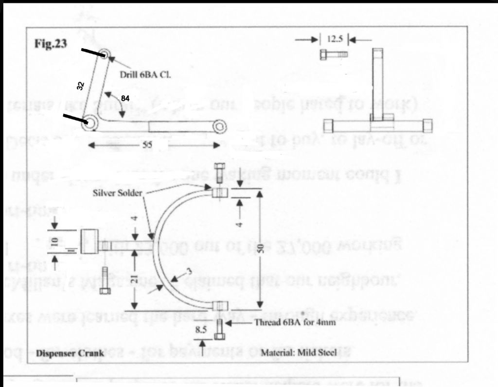
| 829 forum posts 1 photos | Is it just me or is that drawing mixing first and third-angle projections? |
| JasonB | 09/07/2011 17:37:02 |
 25215 forum posts 3105 photos 1 articles | I think its you, looks OK to me.
J |
| Gone Away | 09/07/2011 18:38:35 |
| 829 forum posts 1 photos | The boss in the corner is longer on one side than the other. In the top left view, is it longer on the side facing you or on the far side? (And, if they're consistent, are the other two views first or third angle projections?) |
| JasonB | 09/07/2011 18:44:05 |
25215 forum posts 3105 photos 1 articles | Longer on the far side as the photo confirms, all 3rd angle |
| Gone Away | 09/07/2011 18:54:39 |
| 829 forum posts 1 photos | Then the lower view is wrong (or first-angle). |
| JasonB | 09/07/2011 18:59:22 |
25215 forum posts 3105 photos 1 articles | Well the plan should really be above the two elevations for 3rd angle or if layed out as is then yes the boss should be the otherway round and the end of teh arm shown dotted effectively making it a view from below if you want 1st angle. But like I said in the other post I could make it from those drawings given the missing dimension and confirmation of the angle that I mentioned earlier which is what really matters.
Also all the other drawings in 4407 use the same layout so at least they are consistant

Edited By JasonB on 09/07/2011 19:03:32 |
| David Clark 1 | 09/07/2011 19:31:23 |
 3357 forum posts 112 photos 10 articles | Hi There
Tha angle has to be wrong or it is drawn incorrectly.
I will check with Brian on Monday.
regards David
|
| Gone Away | 09/07/2011 22:44:30 |
| 829 forum posts 1 photos | Posted by JasonB on 09/07/2011 18:59:22: Well the plan should really be above the two elevations for 3rd angle or if layed out as is then yes the boss should be the otherway round and the end of teh arm shown dotted effectively making it a view from below if you want 1st angle. With respect Jason, that elevation is not described as a "plan" nor is there any compulsion in any drawing standards that I've ever come across (formal or informal) to include any specific elevations/views. Simply that sufficient elevations/views be included to completely describe the part. In that case, and if this is indeed intended as third-angle, then the lower elevation would logically be interpreted as a view on the bottom of the view above it and the elevation to the right as a view of the right side. As such, they are inconsistent. Yes, you may be able to make the part by scrounging around for other information but any drawing should stand alone and give enough information to make the part. I sense that you don't think this is particularly important. Dimensional errors may occur occasionally even on professionally produced drawings (particularly those that are/were manually generated) but nothing else more clearly says "amateurish" or leads to more confusion, than inconsistent projection standards. |
| blowlamp | 10/07/2011 00:01:50 |
 1885 forum posts 111 photos | As a little test, I've roughly scaled the drawing to the 50mm reference line and overlayed a few arcs and lines with their actual dimensions and some are pretty far out, as can be seen in the picture.
The large arc is ok, but the smaller one is not so good when compared to the theoretically correct one I've put in.
The 21mm measurement is miles out, as is the 39mm one.
I know we don't scale from the drawing, but it should bear a closer resemblance to reality than this one appears to.
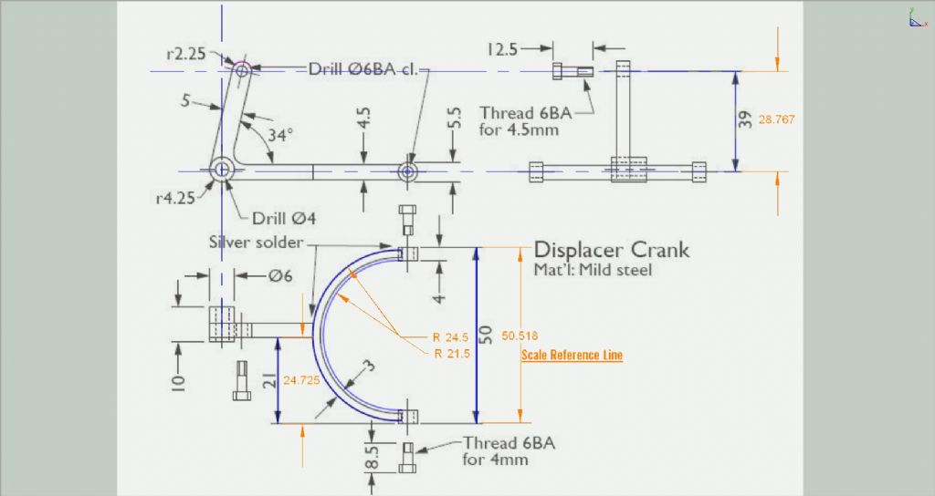 Martin. |
| JasonB | 10/07/2011 07:44:56 |
25215 forum posts 3105 photos 1 articles | At the risk of these errors getting lost in another epic drawing standards thread could I ask that we keep this thread to the actual errors so its easier for future builders to locate corrections. Having said that....
Sid, the use of "Plan" comes from my construction background where the view from above is generally termed the Plan View, from the side Elevations and rarely from below would be inverted plan. What I was saying is they are consistant in as much as all the drawings for this engine in both 4407 & 4408 use the same mixed projection eg 3rd angle for the elevations with what should be the 3rd angle view from above placed below the elevations rather than above. Still could be worse, the Rina has one drawing in 1st and the other in 3rd, now that is inconsistant.
Martin thanks for taking the time to draw the part out and it does raise the point that without a drawing being drawn in proportion its very hard to spot if a dimension has been printed wrongly. A point for David to take up with Stavros the illustrator.
Interesting that the 39mm is so far out, if it were drawn the correct length then it may mean the angle is supposed to be 84deg as I suggested rather than the 77 it measures off the drawing
J Edited By JasonB on 10/07/2011 07:47:47 |
| David Clark 1 | 10/07/2011 09:15:44 |
3357 forum posts 112 photos 10 articles | Hi There
The text says the centre bar is offset, so the 21 is probably correct.
The drawings may not be to scale.
The drawings are made from the originals and if they are not supplied to scale they will not be redrawn to scale.
The same goes for projection.
We have time to tidy up what we get, we don't have time to redraw and redesign everything.
If we did that, we would have to make another model to prove the dimensions.
regards David
|
| Eric Cox | 10/07/2011 10:21:57 |
 557 forum posts 38 photos | .The 34 degree angle should be a reference dimension and the position of the 6BA clearance hole should be dimensioned relative to the X-Y axis. Edited By Eric Cox on 10/07/2011 10:26:18 Edited By Eric Cox on 10/07/2011 10:35:49 |
| JasonB | 10/07/2011 11:31:35 |
25215 forum posts 3105 photos 1 articles | I would have thought that the curved dimension line indicates that it should be an angular measurement.
But agree that teh hole could be positioned using teh 39mm and a second dimension fort teh other axis. |
| David Clark 1 | 11/07/2011 19:35:23 |
3357 forum posts 112 photos 10 articles | Hi There
Updated dimensions.
84 is correct measured from original.
regards david
 |
| JasonB | 11/07/2011 20:44:42 |
25215 forum posts 3105 photos 1 articles | Thanks for that David.
It now raises the question regarding the length of the arm, 32 along the diagonal on the original, 39 vertacally on the mag drawing. I see this is in a darker font is this something you have added? |
| David Clark 1 | 12/07/2011 08:06:13 |
3357 forum posts 112 photos 10 articles | Hi There
I added the 84 degrees, 32, the 55 and the 1 after talking to Brian.
Brian had to bend the 84 degrees to fit which is why the drawing angle is different.
The actual model is 84 degrees.
regards David |
Please login to post a reply.
Magazine Locator
Want the latest issue of Model Engineer or Model Engineers' Workshop? Use our magazine locator links to find your nearest stockist!
Sign up to our Newsletter
Sign up to our newsletter and get a free digital issue.
You can unsubscribe at anytime. View our privacy policy at www.mortons.co.uk/privacy
Latest Forum Posts
- hemingway ball turner
04/07/2025 14:40:26 - *Oct 2023: FORUM MIGRATION TIMELINE*
05/10/2023 07:57:11 - Making ER11 collet chuck
05/10/2023 07:56:24 - What did you do today? 2023
05/10/2023 07:25:01 - Orrery
05/10/2023 06:00:41 - Wera hand-tools
05/10/2023 05:47:07 - New member
05/10/2023 04:40:11 - Problems with external pot on at1 vfd
05/10/2023 00:06:32 - Drain plug
04/10/2023 23:36:17 - digi phase converter for 10 machines.....
04/10/2023 23:13:48 - More Latest Posts...
- View All Topics
Support Our Partners


Shopping Partners
Subscription Offer

Latest "For Sale" Ads
- Reeves** - Rebuilt Royal Scot by Martin Evans
by John Broughton
£300.00 - BRITANNIA 5" GAUGE James Perrier
by Jon Seabright 1
£2,500.00 - Drill Grinder - for restoration
by Nigel Graham 2
£0.00 - WARCO WM18 MILLING MACHINE
by Alex Chudley
£1,200.00 - MYFORD SUPER 7 LATHE
by Alex Chudley
£2,000.00 - More "For Sale" Ads...
Latest "Wanted" Ads
- D1-3 backplate
by Michael Horley
Price Not Specified - fixed steady for a Colchester bantam mark1 800
by George Jervis
Price Not Specified - lbsc pansy
by JACK SIDEBOTHAM
Price Not Specified - Pratt Burnerd multifit chuck key.
by Tim Riome
Price Not Specified - BANDSAW BLADE WELDER
by HUGH
Price Not Specified - More "Wanted" Ads...
Get In Touch!
Do you want to contact the Model Engineer and Model Engineers' Workshop team?
You can contact us by phone, mail or email about the magazines including becoming a contributor, submitting reader's letters or making queries about articles. You can also get in touch about this website, advertising or other general issues.
Click THIS LINK for full contact details.
For subscription issues please see THIS LINK.
Digital Back Issues


Donate

 Register
 Log-in
Model Engineer Magazine
- Percival Marshall
- M.E. History
- LittleLEC
- M.E. Clock

ME Workshop
- An Adcock
- & Shipley
- Horizontal
- Mill

Subscribe Now
- Great savings
- Delivered to your door

Pre-order your copy!
- Delivered to your doorstep!
- Free UK delivery!
All Forum Topics > Drawing Errors and Corrections > No 4407 More Errors