Forum sponsored by:

Multiple Bearings in Spindle
| Kiwi Bloke | 28/07/2023 06:02:06 |
| 912 forum posts 3 photos | I'm naturally lazy, and my scrap bin has a nasty self-filling habit. so simplicity is attractive. The spindle and spacer tube are the easy (easier) bits, particularly if simplified further, as I've suggested. I would do as much as possible on the spindle between centres, then rough out the collet taper, and follow Duncan Webster's advice to finish bore it, supporting the shaft end either in its bearing, or directly, by a steady. Don't rely on collets (especially cheapo ones!) for concentricity, even if there's an apparently long-enough surface to grip. And remember that, whilst you can 'dial in' something in a 4-jaw chuck, to run true where the indicator's probe bears, things might be different at some distance from the chuck. You can't rely on the jaws to hold exactly parallel to the lathe's axis (they should, of course, but don't make assumptions...). It's the housing that's to my mind the most challenging. If it's to be a quill, you presumably need the bearing seats to be concentric with its OD. You might consider making a mandrel, so that the housing OD can be finish-turned on the mandrel, between centres. I'd try to avoid doing anything tricky down at the bottom of a bore, so my previous comments stand. |
| Michael Gilligan | 28/07/2023 06:51:37 |
 23121 forum posts 1360 photos | Clearly impractical for Steve’s project, but I would just mention how Gepy does the concentricity thing: **LINK** : http://anglo-swiss-tools.co.uk/gepy-centres-spindles/ MichaelG. |
| Ian P | 28/07/2023 11:58:55 |
 2747 forum posts 123 photos | I would say the Kiwi bloke has pretty much summed up the important bits to consider when making the spindle parts. If I were to make one to the highest precision I could, I would machine the spindle between centres to an almost completed state except for the female cone. Leaving the ER end solid allows machining all the external surfaces, threading and bearing registers being lapped whilst the spindle can be taken can be taken on and off the lathe to check fits etc. The conical bore can then be rough machined just using the three jaw chuck. I would finish grind the ER taper later with the spindle running in its own bearings. I would avoid making a spacer between the (front) bearings (version 8) just because if we are talking high precision, its just another item that has to have absolutely parallel faces to avoid tilting a bearing. The tubular spacer in version 8 has machined features at both ends which are not really needed. The outer annulus area of a flat face at the tail end will be in fresh air and shortening the shaft (front) bearing register will allow the spacer flat front face to sit against the inner race. Maybe I have missed it earlier in this thread but I am not sure what type of ballraces are being used. As the over length of the whole assembly is quite short and as its intended use should not require it to take excessive side loads then I would just have front and back only as that would eliminate the need for the thread and but arrangement in the outer body. A thin close fitting (to the shaft) 'washer' could be pressed into the front bore to keep swarf out freeing up a bit more axial length for flats etc. Ian P
|
| Michael Gilligan | 28/07/2023 13:42:18 |
23121 forum posts 1360 photos | Posted by Andy_G on 27/07/2023 10:34:49: […] I'm not sure what material Steve is thinking of for the housing, but in the design with a spacer between the inner races only, I would suggest that the housing be made of steel, rather than aluminium, in order to avoid variations in bearing preload as the spindle warms up - I tried something similar with an aluminium housing and the temperature effect was remarkably noticeable. […] . I offer one of those near-random thoughts that pop into the mind unexpectedly: If the housing was made from Machinable Technical Ceramic, the effect of warming should be to reduce the preload … making the device “fail-safe” https://www.final-materials.com/gb/226-machinable-technical-ceramics MichaelG. |
| Andy_G | 28/07/2023 14:58:29 |
 260 forum posts | Posted by Michael Gilligan on 28/07/2023 13:42:18:.
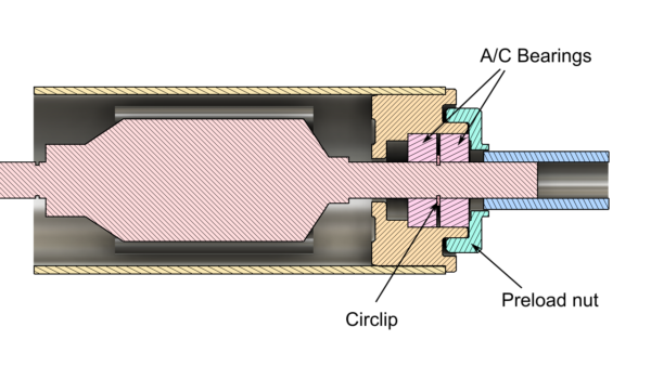
If the housing was made from Machinable Technical Ceramic, the effect of warming should be to reduce the preload … making the device “fail-safe” The problem I had with the aluminium housing was that the preload reduced / disappeared when it got warm. If the preload was adjusted to 'take the slack out' in this condition, then the spindle almost seized when it cooled down. This was with a solid spacer between the inner races (a circlip for various reasons) and an adjustable nut to preload the outer races against each other:
Unless I'm missing something, the same arrangement with a [low expansion] ceramic housing would do the opposite: i.e. preload would tighten up as the temperature increases. Incidentally, something to consider is that matched pairs of angular contact bearings suitable for face to face mounting are available, fairly cheaply, as spare parts for Chinese made CNC router spindles. Face to face mounting takes the expansion of the housing out of the equation. The quality of the ones that I have bought has been pretty good. Edited By Andy_G on 28/07/2023 15:00:04 |
| Michael Gilligan | 28/07/2023 15:26:52 |
23121 forum posts 1360 photos | You are probably right, Andy As I said it was just an unexpected thought … I should have ‘thunk it through’ before posting. MichaelG. |
| Iain Downs | 28/07/2023 16:46:38 |
| 976 forum posts 805 photos | Just wanted to say thankyou for the useful comments. My own use case is to put the spindle cartridge in the spindle of my mill and drive the (high speed) spindle from a motor hanging off the cartridge. The drawing below my give an idea.
Left is the spindle (cheap Chinese ER11 'extension rod' The spindle is supported on bearings at the top and bottom of the cartridge, loctited in. I've also made a version with preload applied by nut with a thread on the top of the HS spindle (cuts fine with single point threading) though that performed somewhat worse than the one which was just glued. The specific thing I wanted to achieve is to be able to mount the high speed spindle in the mill and have it be correctly registered. I could, for example rough something out with a 10mm end mill and tidy up with a 1mm mill. This kind of works ( drilling with sub 1mm drills is entirely possible now), but the run out is bigger than I'd like. I'm not sure if all the complications of Steve's spindle is really required for what I want. In particular, going mad for rigidity may make little sense if I have a bit sticking out with a drive on it! I'd be interested in any suggestions or comments before I build my next prototype. Iain |
| Andy_G | 28/07/2023 18:35:32 |
260 forum posts | Posted by Iain Downs on 28/07/2023 16:46:38:
The specific thing I wanted to achieve is to be able to mount the high speed spindle in the mill and have it be correctly registered. I could, for example rough something out with a 10mm end mill and tidy up with a 1mm mill. This kind of works ( drilling with sub 1mm drills is entirely possible now), but the run out is bigger than I'd like. I'm not sure if all the complications of Steve's spindle is really required for what I want. In particular, going mad for rigidity may make little sense if I have a bit sticking out with a drive on it Have you checked the runout of the taper on the ER11 collet extension with respect to its own shaft? I have had a couple of shockingly bad ones and one very good one (roughly similar prices). Similarly, 'cheap' ER11 collets vary widely in their ability to run true. Could you put the drive pulley on the rear of the bearing arrangement so that there was less overhang at the front bearing? IMHO, it's well worth trying to minimise tool overhang, to minimise the effect of spindle runout / lack of straightness. The smaller the tool diameter, the better the runout needs to be. This is the arrangement for a toolpost spindle I made using the good ER11 collet extension. It is driven from the rear by a timing belt pulley:
The motor is mounted piggy-back:
I wouldn't use the double row A/C bearing again (it still needs to be preloaded to remove slop - I didn't realise until after I'd made it). If I were to make one using an ER collet extension holder again, I'd probably use a similar configuration, but with a single bearing at each end (maybe A/C or maybe plain ball bearing, depending on likely loads & budget at the time). I think it would be a compromise compared to machining a spindle to one of the designs above, though. (Sorry, I didn't intend to monopolise this thread - it's just a topic that I have given quite a bit of thought to over the last few years!) Edited By Andy_G on 28/07/2023 18:36:00 |
| Steve Crow | 28/07/2023 18:36:51 |
| 429 forum posts 268 photos | I've only just read the latest postings as I've been in the workshop all day. Those boring bar holders don't make themselves! And I've got a feeling I might need them. A word about collets and workholding regarding the spindle machining. A couple of comments mentioned concentricity of collets. I've recently made an ER16 chuck for my headstock. Machined in place, it has no measurable run out. I bought a set of ultra-high precision collets (5 micron) and they are excellent, on an other level to any I've had before. Checking them with a test bar of nominal diameter (so there is hardly any compression) I get a run out of 2 to 3 um and I can half that by careful tightening (final 2 nips at 180 to each other) so I have confidence in my collets. Saying that, Duncan Webster was right, that 9.5mm diameter is far too short (4mm) to be gripped accurately. ER collets should grip on their full length for best accuracy. That's 27mm for a ER16. I could hold on the 8mm journal length instead which is 16mm long. As its being held in a 8mm collet, all should be good. After all, I'll be checking and skimming the taper in the final stage, when held true by the front bearings. When I do the final stage, I'll hold the tail end in a watchmakers collet which grips on a shorter length. The only time I'll be using a 4-jaw is the first stage, supported by a centre. As all diameters are turned in the same set up, everything should be concentric. I could even do it in the 3-jaw with oversize stock and turn down to 10mm for the collet when I reverse it. I will get round to describing how I plan the make the housing eventually but it's beer o'clock. Steve
|
| Iain Downs | 28/07/2023 19:39:59 |
| 976 forum posts 805 photos | Andy - the runouts do seem to vary quite a bit, though I found the worst part is generally the collet nut (some of which are unusable. Some are quite good and I have collets which claim to be decent. the point of my design is to put it in a collet in a (locked) mill spindle -not much chance of driving that from behind! Iain
|
| Andy_G | 28/07/2023 23:16:53 |
260 forum posts | Posted by Iain Downs on 28/07/2023 19:39:59:
the point of my design is to put it in a collet in a (locked) mill spindle -not much chance of driving that from behind! Sorry, I misunderstood - I read it that you had a separate high speed spindle, offset from the mill spindle, with some sort of mounting bracket held in the mill collet - my apologies. |
| Steve Crow | 29/07/2023 18:22:07 |
| 429 forum posts 268 photos | I do want to make a longer quill version of this. That will have to have the housing trued on a mandrel as mentioned by Kiwi Bloke. However, I'm going to concentrate on the short version first to prove the concept, so to speak. The housing will be steel, probably EN1A. Much as I would like to bore everything from the front, I have zero confidence in getting the rear bearing diameter right. And as for cutting the O-ring groove? Forget about it. I'm going to cut and face to size then centre in a 4-jaw. A few minutes with a little nylon hammer on the tail end and careful tightening and in my experience you can get both ends near true. The whole housing is less than 48mm long and a third of that is in the chuck jaws so I'm not sure a steady is needed. Drill and bore to suit rear bearing all the way through. Cut O-ring groove. Reverse in chuck and clock both ends but this time on the chuck end and the bore. Bore for clearance, nose bearings and nose inner nut. Have said nose inner nut ready (that you made earlier) for testing the fit and cut internal threads. I don't know the first thing about O-rings by the way. If anyone can enlighten me to what I need for this application? Steve |
| Andy_G | 29/07/2023 21:14:41 |
260 forum posts | Posted by Steve Crow on 29/07/2023 18:22:07:
I don't know the first thing about O-rings by the way. If anyone can enlighten me to what I need for this application? The O-ring isn't particularly critical - find one with an ID that matches the bearing OD (within a few %) and has a section diameter that is less than ~25% of the bearing width. Cut the groove in the housing to ~90% of the O-ring section deep by somewhere between ~125% and ~150% of the O-ring section wide (not critical). The groove is roughly centered on the bearing location. (The groove could be machined in a different setup to machining the bore because any sight lack of concentricity doesn't matter.)
|
| Steve Crow | 29/07/2023 23:29:09 |
| 429 forum posts 268 photos | Posted by Andy_G on 29/07/2023 21:14:41:
Posted by Steve Crow on 29/07/2023 18:22:07:
I don't know the first thing about O-rings by the way. If anyone can enlighten me to what I need for this application? The O-ring isn't particularly critical - find one with an ID that matches the bearing OD (within a few %) and has a section diameter that is less than ~25% of the bearing width. Cut the groove in the housing to ~90% of the O-ring section deep by somewhere between ~125% and ~150% of the O-ring section wide (not critical). The groove is roughly centered on the bearing location. (The groove could be machined in a different setup to machining the bore because any sight lack of concentricity doesn't matter.)
Thanks for that, In that case, I've seen O-rings that will fit. I'd rather cut the groove when boring rather than go through the whole faff of setting up again though. Edited By Steve Crow on 29/07/2023 23:29:37 |
| Steve Crow | 31/07/2023 18:19:28 |
| 429 forum posts 268 photos | I've ordered the bearings and will start on the spindle as soon as I've got a current project out of the way. I need to buy/make a couple of tools for this anyway. When I start the build, I'll open another thread as this one is getting bloated. Thanks to everyone who contributed to this, it really is a committee design. If anyone spots a major flaw in my plans, speak up quick! Cheers Steve |

 which runs in a 'cartridge' (some imagination is required to see the bottom part as an ER11 collet and above that a timing pulley). Attached to the bottom of the cartridge is a bracket that holds the motor (in my case a 200W Chinese thing). Again imagine the timing belt between the two,

Please login to post a reply.
Magazine Locator
Want the latest issue of Model Engineer or Model Engineers' Workshop? Use our magazine locator links to find your nearest stockist!
Sign up to our Newsletter
Sign up to our newsletter and get a free digital issue.
You can unsubscribe at anytime. View our privacy policy at www.mortons.co.uk/privacy
Latest Forum Posts
- hemingway ball turner
04/07/2025 14:40:26 - *Oct 2023: FORUM MIGRATION TIMELINE*
05/10/2023 07:57:11 - Making ER11 collet chuck
05/10/2023 07:56:24 - What did you do today? 2023
05/10/2023 07:25:01 - Orrery
05/10/2023 06:00:41 - Wera hand-tools
05/10/2023 05:47:07 - New member
05/10/2023 04:40:11 - Problems with external pot on at1 vfd
05/10/2023 00:06:32 - Drain plug
04/10/2023 23:36:17 - digi phase converter for 10 machines.....
04/10/2023 23:13:48 - More Latest Posts...
- View All Topics
Support Our Partners


Shopping Partners
Subscription Offer

Latest "For Sale" Ads
- Reeves** - Rebuilt Royal Scot by Martin Evans
by John Broughton
£300.00 - BRITANNIA 5" GAUGE James Perrier
by Jon Seabright 1
£2,500.00 - Drill Grinder - for restoration
by Nigel Graham 2
£0.00 - WARCO WM18 MILLING MACHINE
by Alex Chudley
£1,200.00 - MYFORD SUPER 7 LATHE
by Alex Chudley
£2,000.00 - More "For Sale" Ads...
Latest "Wanted" Ads
- D1-3 backplate
by Michael Horley
Price Not Specified - fixed steady for a Colchester bantam mark1 800
by George Jervis
Price Not Specified - lbsc pansy
by JACK SIDEBOTHAM
Price Not Specified - Pratt Burnerd multifit chuck key.
by Tim Riome
Price Not Specified - BANDSAW BLADE WELDER
by HUGH
Price Not Specified - More "Wanted" Ads...
Get In Touch!
Do you want to contact the Model Engineer and Model Engineers' Workshop team?
You can contact us by phone, mail or email about the magazines including becoming a contributor, submitting reader's letters or making queries about articles. You can also get in touch about this website, advertising or other general issues.
Click THIS LINK for full contact details.
For subscription issues please see THIS LINK.
Digital Back Issues


Donate

 Register
 Log-in
Model Engineer Magazine
- Percival Marshall
- M.E. History
- LittleLEC
- M.E. Clock

ME Workshop
- An Adcock
- & Shipley
- Horizontal
- Mill

Subscribe Now
- Great savings
- Delivered to your door

Pre-order your copy!
- Delivered to your doorstep!
- Free UK delivery!
All Forum Topics > General Questions > Multiple Bearings in Spindle