Forum sponsored by:

Chester Super Lux advice
| Taf_Pembs | 09/03/2023 11:44:47 |
| 126 forum posts 96 photos | Aftnoon..! A little progress, things are very slow now I'm 1 handed for a bit post surgery but we're getting there.. (but then they said that about British Rail!). Boring went remarkably well, hit all the numbers I wanted to. While the head stock was still mounted in the lathe I got the liner out of the freezer and with the liner against the face plate used the carriage (and tail stock for the last bit) to press it into the head. Went in perfectly although I stopped short as the top end of the bore has a really thin section for clearance to 1 of the gear shafts, I didn't want to be cracking it for the sake of losing about 1 inch of the liner.
And the thin bit, after boring it's only about 2 mm thick..
Some odd what I can only assume are chatter patterns in the very top end of the original bore but not an issue, it was fine once the cutting had more meat around it. Liner now fitted, bored and honed.. The sleeve may need another very light honing as the Quill needs a little touch to fall out on it's own but going to leave as is until I try it. I did warm the quill up by about 20' C to make sure it would still move to allow for any expansion due to bearing temp increase and it did .. just! Well happy with that. I've now opened up the ports for the Quill lock and the pinion gear, that also seemed to go pretty well, Finished (possibly!) bore and ports.. just a drill hole or 2 for guide pin and lube etc to do but essentially that is done.. not only surprised my self but learnt a lot in the process so a good exercise !
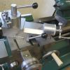
Fly cutter in the lathe to face the end.. had a bit of chatter on the last cut so will need a wee bit more stoning to dress that out.. (below)
What to do next... soo much to choose from.. oil grooves, drillings to suit 1 shot oiler, column .. then reassemble and check .. gib shims etc.. may be some time.. It will live again - honest!
|
| John MC | 10/03/2023 07:30:58 |
 464 forum posts 72 photos | I'm pleased to see this thread get going again, I recently bought a very similar machine, Cormak ZX7045. I'm hoping Taf's solutions might help me sort it out. Regarding the "sloppy" quill fit, my machine seems okay, a tiny bit of play with the quill almost out of its hole otherwise good. It occurred to me that a simpler solution too removing the play in the quill might be to machine a slit in to the housing and fit a bolt (or two) to close up the unwanted clearance? I've seen this technique used on older industrial machines, probably as a means of compensating for wear rather than achieving the initial fit? I have found a number of problems with the Cormak mill so will start a new thread rather than highjack Taf's thread. John |
| Taf_Pembs | 10/03/2023 11:31:01 |
| 126 forum posts 96 photos | Hi John, It's taking a while to get through this, unfortunately a wrist injury seems to be going backwards not forwards so trying to do everything pretty much 1 handed is just slowing everything down a bit. I was a righty but now pretty well a lefty.. wonderful how the body adapts! There obviously needs to be some play in the quill to allow free movement, but mine was pretty excessive, no issue for milling as the quill would be locked but when drilling, the distance down to the end of the bit amplified the problem. As there was no obvious or measurable ware on the 2 small contact rings (machining marks barley touched) in the quill sleeve and nothing on the quill I decided to do something about it. It was just made really poorly. It has worked fantastic as well as given me much more confidence and now instead of 2 short contact rings fairly close together low down the bore I have pretty well full length support to the quill.. a huge difference, looking forward to trying it but at this rate that will be some time!
I don't regret buying it, far from it I love a challenge and really enjoying doing it and when its done I reckon I'll have a fairly decent machine although the list of jobs I had lined up for it is growing somewhat!
|
| Lathejack | 10/03/2023 16:53:15 |
| 339 forum posts 337 photos | Great work, and a fairly major task. It must have been a little daunting to finally switch on and start taking the first cut in the bore, no turning back once you get going. I've often wondered how much bearing surface there is inside the bore for the quill on many of these mills. From your earlier photos, and other images of them, I had assumed they had bored the full length of the internal casting, or most of it, to fit the quill. So was a bit disappointed that there was only a couple of short areas of bearing surface for the quill, but I suppose that is a lot quicker and easier for the manufacturer. The Condore and Bridgport mills we have at work, and the new Bridgeport clones I have looked at, have a quill that is a very close fit in the head casting, so there is a small amount of drag on the sliding quill. A Hobbymat BFE mill I once owned was manufactured with a cast iron liner in the Alluminium alloy head casting that was bored and honed with a cross hatch pattern to a very close fit to the quill, with no detectable play and a small amount of drag on the quill. Where did you get the iron liner from? What was it originally intended for, or was it made to suit your purpose? I have a lightly used 1997 Taiwanese made Warco VMC mill that I bought when it was only a few months old. The head casting is bored for its full length to suit the quill diameter, and there is a small amount of clearance around the quill which is a free sliding fit in the bore with no drag. This clearance really shows up when using a boring head with its single point cutter, as the quill slides further out lubricating oil can just be seen being squeezed in and out of the small clearance as the quill rolls around in the bore as the single cutter rotates. Anyway, really great work and always interested to see more. |
| Taf_Pembs | 10/03/2023 19:14:04 |
| 126 forum posts 96 photos | Thanks for the encouragement, appreciate it! As long as some folk find it useful or worth reading I'll keep posting how how it goes. Yes, there was a fair amount of nerves taking the first cut, I went though it dry so to speak many times before actually cutting to try to make sure what I was doing was going to work.. measure twice cut once?.. no.. measure 20 times and cut once! As a get out I had spoken to a couple of local machine shops to get an idea of what it would cost me to put right if I cocked it up .. a couple of hundred quid although I expect a good engine boring firm would be somewhat less as they have dedicated boring and honing set up's ready to go.
The Liner came from Westwood Cylinder Liners *Here* .Browsed by size and came up with the WCL 16B. I had thought originally to use the WCL 16CFL that was much thicker and with a lip but no need to take anything like that amount of material. The WCL 16B was about £52 with vat and carriage Carriage was expensive, 12 quid + vat I think but was the right one for the job.
|
| John MC | 13/03/2023 07:59:51 |
464 forum posts 72 photos | Another thought on removing the excess clearance from the quill. Chrome plate the quill. A generous layer of decorative chrome might do it, If not then industrial chrome. Reduce the diameter of the quill, plate to oversize then grind to suit the hole. The rack and internal features can be masked so as not to alter its sizes. This works very well on Bridgeport mills, among others. As for costs, don't know. Probably not that expensive as its a common enough process these days. Taf, hope the work on the mill is progressing well, keep the thread going, its interesting. John
|
| mgnbuk | 13/03/2023 11:11:39 |
| 1394 forum posts 103 photos | As for costs, don't know. Probably not that expensive as its a common enough process these days. The machine tool rebuild / retrofit company I used to work for used the grind / hard chrome / grind to size method to sort out worn ailstock barrels & worn bearing seats on spindles. The parts were larger than model engineering friendly machinery, but 20 years ago the costs were significant & the process slow - an initial grind to remove wear and impart a very good finish to the part before sending out to the platers for the actual plating, then return to the grinder to finish grind. One issue that frequently occurred was the plating not adhering to the component, something that did not reveal itself until the finish grinding operation when the plating would flake off. This required the entire surface to be ground back to the parent metal & then replating. On one component (a Crawford Swift spindle with worn bearing seats) this happened four times before the part was completed - a process that took several weeks. The last part I had repaired this way was the tailstock barrel on a CNC lathe that the operator crashed the tool turret into at rapid traverse This bent the 100 mm diameter barrel by 0.05mm - not a lot, but enough to sieze it in the housing. This was ground on the OD to remove the bend, plated oversize, ground back to original size and the 5MT taper reground true to the OD - IIRC this cost £400 + Vat around 10 years ago. We used to use a company in LIversedge, West Yorks - Brian Kemp Grinders - for this type of work & usually sent both the component to be plated + the component it ran in to them. They honed the bore & ground the plated part to give the required fit. Brian passed away many years ago, but his wife continued to run the company. They still have a current website. I suspect that Taf's solution will be a lot cheaper + produces a full length bore.. Nigel B. |
| Taf_Pembs | 13/03/2023 17:33:00 |
| 126 forum posts 96 photos | Allo..! Plating wasn't really a consideration for me as the bore only had 2 short poorly machined contact areas, 1 right at the bottom and 1 a couple of inches up, just above the quill pinion and quill lock ports. These contact areas were barely 1 &1/2 inches wide each. The rest of the bore was relieved by about 30 thou ish. My thinking was that a 'full contact' bore, even if not the most perfect finish would give far more support and less play than these 2 short rings low down on the quill. Grinding and plating would be the best way to do it I would think if the head / bore were sturdy and accurate enough, silky smooth and no play but way beyond my budget I'm afraid..
Unfortunately I have a far more pressing problem.... |
| Taf_Pembs | 13/03/2023 18:01:03 |
| 126 forum posts 96 photos | So... Houston we have a problem. How to measure the flatness and parallelism of dovetails without a dovetail straight edge and a mic big enough.
When I first got the mill I had real problems adjusting the vertical slide gib. Tight (ish) then proper loose, and nowhere in between. no matter what I did I could get nothing consistent. Even in the tightest area the gib was inserted way to far and would need a serious shim. As the column is still on the work table I thought I would put a light blue on the saddle sliding dovetail and see what it looked like. No point in taking a pic as it was as flat as the Pennines. I did try to scrape some of the lumps down a bit just to get a little more even contact before trying to get some sort of measurements and also an idea of how thick a shim would be needed. The best I could do to to measure was using a pair of 10mm carbide end mills (need 12 or 13 really) and my Mitutoyo vernier (I have learnt to trust it fairly well, its good but no Mic). I thought I was being kift as there was a narrowing of well over 10 thou in the mid area. I placed the saddle on the column at the top area and inserted the gib so just nipped and no play. Measured the stick out of the gib. Then same further down, etc etc. in the mid section the gib sticks out over an inch more than at the top or bottom. I'm reasonably confident that the slide ways are pretty flat as placing the (blued) saddle anywhere on the column produces a full print, I appreciate it's not perfect but all I could do so I believe the issue is with the dovetails.
Going to have to get the thinking cap on and work out a way to get at least 1 dovetail flat then at least I have a starting point. The other thing, the dovetail angle, as best as I can measure, scribing on to paper, angle gauge etc etc is 53 Deg.. I've never seen a 53 Deg cutter and can not find one on the interweb ?? If I could, I'm sure the column could be mounted some how on a mill and skim cut the dovetails. Oh for a camel back .. no chance of affording one ! Not much point in continuing until I can sort this.. I suppose I did say I liked a chalenge!
Any suggestions greatly appreciated!
|
| Taf_Pembs | 13/03/2023 19:50:24 |
| 126 forum posts 96 photos | Ok.. Tutting, laughing, eye rolling, frowning head shaking etc etc.. All the above are fully permitted and no offence will be taken!!
Had a thought on a way to find out if it was 1 side or both or at least to maybe prove that I'm not measuring kift.. I took my cleanest thin straight edge I could quickly lay my hands on, balanced it on the surface plate with a light behind and then gently stoned it until it would sit on its edge with no light showing under the edge.
Laid it against the dovetail with a pair of end mills behind for repeatability and a consistent angle as close to 90 deg to the dovetail as possible. Repeated each side in several positions to confirm repeatability... it seemed to show something I can work with! On the non gib side, no mater where I set it I could not get a 1 thou feeler gauge between edge and dovetail, this is the side I did a wee bit of scraping on. On the Gib Side, in the mid section in the same area I was showing the biggest reduction in when measuring with end mills and calliper, also where the biggest protrusion of the gib was when trying it in the saddle I could easily get a 0.07 / 2.8 thou feeler gauge in the gap and this reduced towards either end of the column.
At least I have something to work with... I think!
The above laughing, tutting, head shaking etc may now commence...
|
| Taf_Pembs | 22/03/2023 15:35:22 |
| 126 forum posts 96 photos | Getting creative with the dovetails..
Really didn't like the ruler, it gave an idea but no good really.
Not having a camel back or any kind of master to be able to print the dovetails has caused much head scratching..
I did email Clive Lamb for a price on an 18" (or his nearest size) camel back to do flats and dovetails and despite being a good price compared to everything I see second hand it was out of reach for me I'm afraid (am saving up though!) - he said the foundry had put prices up around 50% ! So all I needed to do was get 1 side flat then use that to measure to the other to get them parallel. I had a fresh length of ground silver steel 1/2" rod, Ideal side for contact with the mid point of the dovetail, rolled it on the surface plate with a light behind and at 1 point it was in perfect contact along its whole length so I put a sharpie mark on the opposite side so I could lay it in the dovetail in the correct position and used a feeler gauge to find the variation.
Seemed to work pretty well so I used it to check the corresponding dovetail on the saddle and fortunately the non gib side needed almost do scraping to get it bob on. Then used that in the same way as I did doing the flat ways, i.e. start at the lowest area, print it to find the high spots, move a couple of inches to one side or t'other and repeat until regardless of where the on the column I printed I had a full length print.. I may be wrong but I don't see how there can be any variation then (certainly not enough to make any difference to me!). Kept checking with the ground rod just as a check that was I was doing was working. Far from ideal but it seems to have worked! I can now measure to the other side to get parallel. I'm still baffled as to how the whole thing could have been so far out but it certainly explained why when I got the thing and tried to do some cuts, particularly fly cutting, it gave such poor and random results.
I suppose if I manage to finish this thing I'm going to have to find something else to blame for my crap parts!
|
| Taf_Pembs | 24/04/2023 14:29:36 |
| 126 forum posts 96 photos | Afternoon all..
Well.. unfortunately nothing to update, complications from the 3rd round of surgery on my wrist is basically preventing me form moving anything other than the lightest parts round the workshop.. even got to call a mate up to change chucks on the lathe.. can just about manage the 3 jaw and the collet but that's a struggle. I have managed to spend a week or so addressing the damp issue in the workshop.. the render on the main south facing weather wall was cluck as hell .. no issue with the bond to the wall but seriously cracked which I found by scraping some of the paint off. So, after a strip off with a jet wash and painting a waterproofing slurry mix over the whole wall and all the cracks in the other walls I'm now waiting for a decent dry spell to give it a coat of that Bedec extraflex paint to finish the seal of the walls. It should have been a day or 2's work but took well over a week being basically 1 handed.. hay ho.. at least it's keeping me busy and providing a bit of physio.. I am hopefully waiting on a bit of kit that is going to help with the mill but will have to wait and see.. Next job is I have to save up for a new garage door, my sectional insulated electric door takes up around half of the head space so need one that is a roller affair so I can fit a unistrut over head gantry set up to be able to move stuff round the workshop .. if I can do it so it will lift around 80kg that will be fine for what I need then I can get back to doing some useful stuff !
Cheers for now..
|
| larry phelan 1 | 25/04/2023 17:13:30 |
| 1346 forum posts 15 photos | You deserve a medal for hanging in there for so long ! 30 ,10 2022 ? |
| John MC | 26/04/2023 10:29:51 |
464 forum posts 72 photos | Keep going when you are able Taff, you will hve a fine machine in the end! |
| Taf_Pembs | 26/04/2023 21:29:28 |
| 126 forum posts 96 photos | Cheers folks, with a bit of luck and a fair wind there will be some progress soon. I hope so as I have a fair few jobs I need it for, my fixed steady for the lathe has a broken clamp and I need that for another job.
It's becoming a bit like British Rail ... and I'm sure we all know that catch phrase!
|
| Taf_Pembs | 27/05/2023 21:11:07 |
| 126 forum posts 96 photos | Evening all..!
Well.. after lots of saving and reduction in the beer intake for said reason.. its here!!
A wonderful 20" long piece of cast iron art created by Mr Clive Lamb (Thank you Clive) of HR Lamb & Sons Machinery (No affiliation or discount, just good service) .. and what a fine piece it is..
A part finished 20 incher that I have now milled the ends (Cheers Mr J!) and started scraping .. however, it seems my old small steel hand scraper has passed it's hardened end (if it had such a thing) as it needs to have the cutting edge dressed with a stone after only a few scrapes as it starts gouging and scratching rather than scraping. It was pretty short to start with and hence very uncomfortable. So I've also ordered a Rennsteig scraper with carbide insert (Amazon of all places for 42 quid!). I've roughed it in - which really only took a few passes - and will wait for the proper scraper to finish it.
Oh and picked up a proper Kurt D6* in decent condition for a proper win on the bay of stuff.. dam handy to hold it while scraping. (Bit big for the mill mind but will come in handy and couldn't say no at the price.. sorry about the paint colour, it was all I had on the shelf !! ) So the project can continue! British Rail's got nothing on me... getting there indeed.. These dovetails don't stand a chance !
Now for a celebratory beer.. |
| Pete Rimmer | 28/05/2023 19:45:54 |
| 1486 forum posts 105 photos | I have several of his pieces the iron is a joy to scrape and as you say the quality is right up there. What are you using for a reference Taf?
|
| Taf_Pembs | 29/05/2023 00:06:13 |
| 126 forum posts 96 photos | Evening Pete.. Yes, it is a fine piece, need to make a box for it though.. more to add to the to do list! I've an 18" square granite plate, fine for the flat diagonally but need to offset each end an inch for the bevel.. seems to be working fine. I found that using some Wilko cheap yellow oil artists paint mixed with a bit of way oil to use as a contrast makes life so much easier .. works a treat!
|
| Pete Rimmer | 29/05/2023 10:10:51 |
| 1486 forum posts 105 photos | You shouldn't use an unqualified plate as a master for scraping a reference piece like a straight edge. I mean it'll get you fairly close but you would not believe how fast you can wear a dip in a granite. At the very least, print it in both diagonal directions and compare the results. If they are not exactly the same, the plate is worn. Even if they are, the plate might still be worn but you will likely see a difference. Shame you aren't closer to Kent I could lend you a good straight edge as a reference or even lap your plate to grade 0 for you. |
| Alan Jackson | 29/05/2023 10:30:44 |
 276 forum posts 149 photos | Hi Taf, Thank you for recording your struggle to get this mill as good as it will be when finished, Very interesting to see your solutions to the problems. Its going to be a great machine when finished Alan |


Please login to post a reply.
Magazine Locator
Want the latest issue of Model Engineer or Model Engineers' Workshop? Use our magazine locator links to find your nearest stockist!
Sign up to our Newsletter
Sign up to our newsletter and get a free digital issue.
You can unsubscribe at anytime. View our privacy policy at www.mortons.co.uk/privacy
Latest Forum Posts
- *Oct 2023: FORUM MIGRATION TIMELINE*
05/10/2023 07:57:11 - Making ER11 collet chuck
05/10/2023 07:56:24 - What did you do today? 2023
05/10/2023 07:25:01 - Orrery
05/10/2023 06:00:41 - Wera hand-tools
05/10/2023 05:47:07 - New member
05/10/2023 04:40:11 - Problems with external pot on at1 vfd
05/10/2023 00:06:32 - Drain plug
04/10/2023 23:36:17 - digi phase converter for 10 machines.....
04/10/2023 23:13:48 - Winter Storage Of Locomotives
04/10/2023 21:02:11 - More Latest Posts...
- View All Topics
Support Our Partners


Shopping Partners
Subscription Offer

Latest "For Sale" Ads
- Reeves** - Rebuilt Royal Scot by Martin Evans
by John Broughton
£300.00 - BRITANNIA 5" GAUGE James Perrier
by Jon Seabright 1
£2,500.00 - Drill Grinder - for restoration
by Nigel Graham 2
£0.00 - WARCO WM18 MILLING MACHINE
by Alex Chudley
£1,200.00 - MYFORD SUPER 7 LATHE
by Alex Chudley
£2,000.00 - More "For Sale" Ads...
Latest "Wanted" Ads
- D1-3 backplate
by Michael Horley
Price Not Specified - fixed steady for a Colchester bantam mark1 800
by George Jervis
Price Not Specified - lbsc pansy
by JACK SIDEBOTHAM
Price Not Specified - Pratt Burnerd multifit chuck key.
by Tim Riome
Price Not Specified - BANDSAW BLADE WELDER
by HUGH
Price Not Specified - More "Wanted" Ads...
Get In Touch!
Do you want to contact the Model Engineer and Model Engineers' Workshop team?
You can contact us by phone, mail or email about the magazines including becoming a contributor, submitting reader's letters or making queries about articles. You can also get in touch about this website, advertising or other general issues.
Click THIS LINK for full contact details.
For subscription issues please see THIS LINK.
Digital Back Issues


Donate

 Register
 Log-in
Model Engineer Magazine
- Percival Marshall
- M.E. History
- LittleLEC
- M.E. Clock

ME Workshop
- An Adcock
- & Shipley
- Horizontal
- Mill

Subscribe Now
- Great savings
- Delivered to your door

Pre-order your copy!
- Delivered to your doorstep!
- Free UK delivery!
All Forum Topics > Manual machine tools > Chester Super Lux advice