Forum sponsored by:

Muncaster's Simple Entablature Engine
| john Chappell 1 | 11/10/2019 07:38:39 |
| 14 forum posts 3 photos | Hi Jason, Thanks. Yes I am up to issue 4620 but awaiting some cast iron. 60 Dia mm as far as I can see you can't get it out of 50mm. Where is the extract for the gland? I am using a Wabeco CNC mill for some parts it makes things much easier. It would have been helpful if you could have given a list of materials when the series started as where I live I have to order from a company 2000KMS AWAY and have to wait quite a while for delivery. Keep up the good work, Regards, John Sunshine coast , Australia
|
| paul rayner | 11/10/2019 08:36:51 |
| 187 forum posts 46 photos | Hiya John Posted by john Chappell 1 on 11/10/2019 07:38:39: Yes I am up to issue 4620 but awaiting some cast iron. 60 Dia mm as far as I can see you can't get it out of 50mm.
You can get the cylinder out of 50mm bar, just don't put the hole through the middle like I did in the first one regards paul |
| john Chappell 1 | 11/10/2019 10:26:32 |
| 14 forum posts 3 photos | Thanks Jason, So the guides are actually pieces silver soldered together? John |
| Rockingdodge | 11/10/2019 13:18:44 |
 396 forum posts 111 photos | Hi John, I think you'll find the guides are milled out of solid, you wouldn't be able to join then and get the strength required to resist movement whatever way you joined them. Roger |
| JasonB | 11/10/2019 16:19:07 |
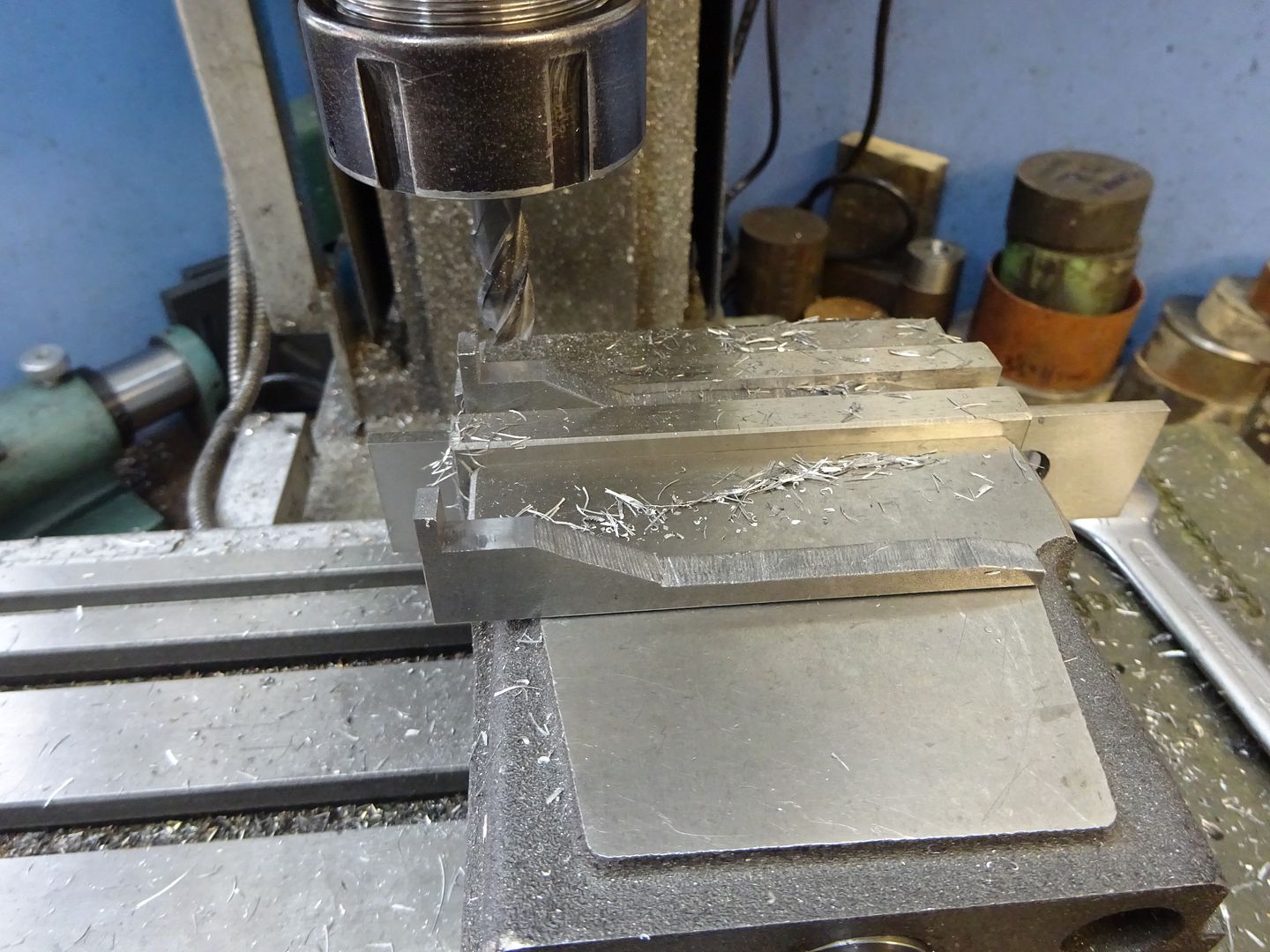
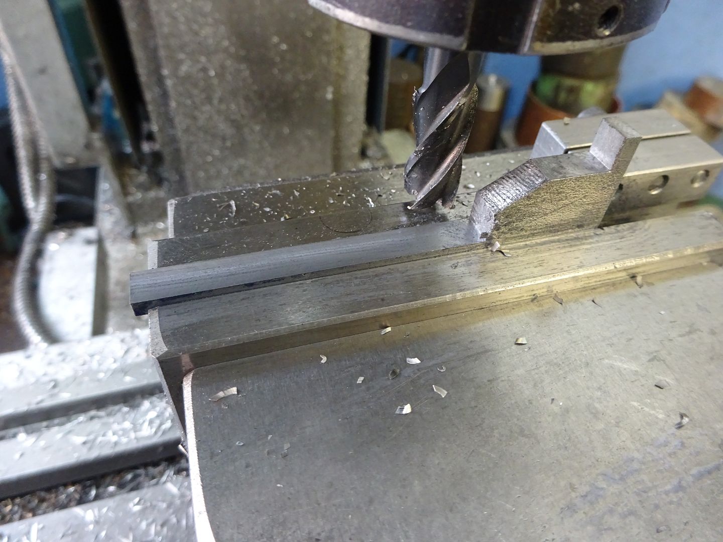
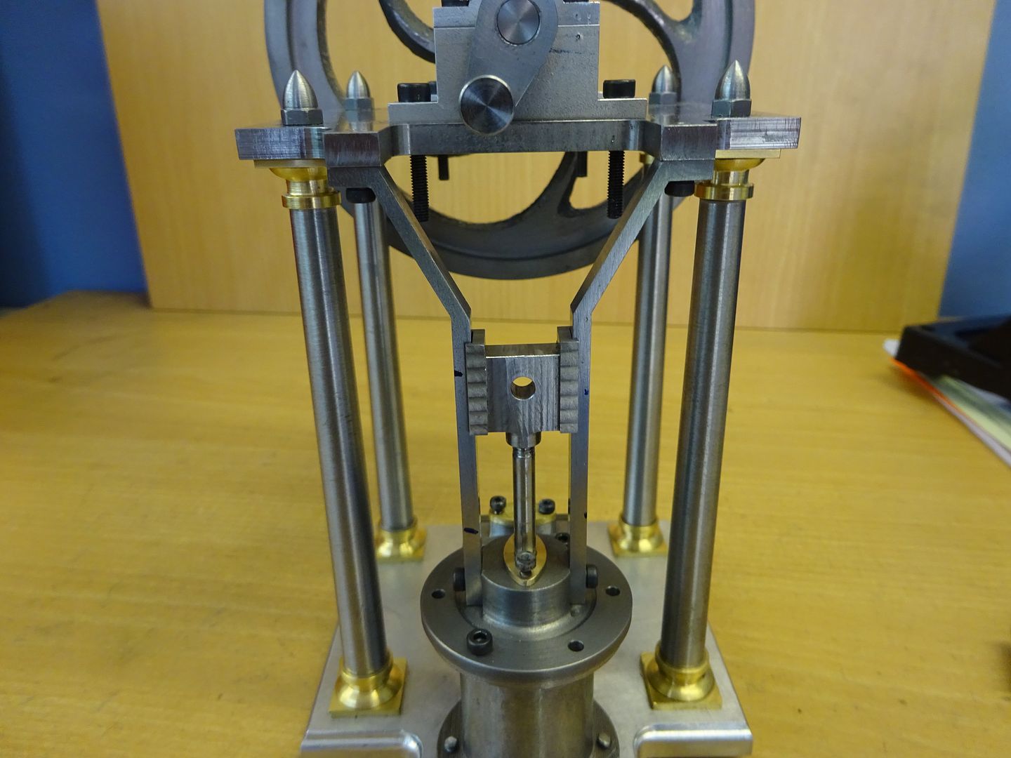
 25215 forum posts 3105 photos 1 articles | The guides are indeed cut from solid. This is basically as described in the text but photos will be a bit bigger: First machine your two pieces of 6mm thick material to the overall 79.5mm x 20.0mm, then mark out so you can saw away most of the waste. Now hold in the vice with the inner face resting on parallels and mill down the 6.2mm leaving 3mm which forms the horizontal leg.
Hold the part again with the inner face resting on a parallel but use a thicker one this time and mill the outerface for a length of 55.3mm from the bottom of the part and again leave 3mm thickness of material to form the vertical leg.
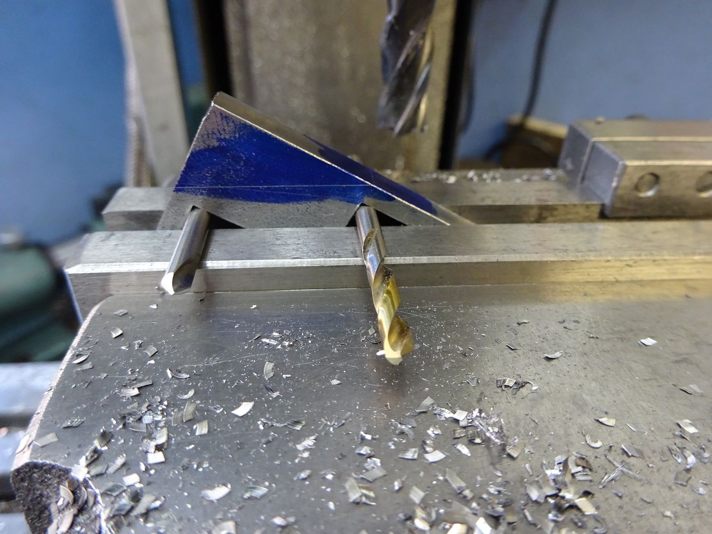
You can now blue the inner edge of the part and mark a line 23.5mm down which is just visible in the photo and I also carried a line around from that to show where the metal will be removed to but that is optional. Slip two matching diameter rods or drill bits onto the vice and use them to support the two internal corners machined in the earlier steps. This will hold the work at the correct angle so no measuring required, just machine down until the cutter is at the marked line on the side.
The final operation is to turn the part the other way up so the sloping face you just machined is resting on a parallel and mill out the remaining material to leave a 3mm finished thickness. No pic of that.
As for the cylinder that will indeed come out of 50mm stock as per the article, just offset the bore of teh cylinder, something like 4mm will do nicely and leave plenty to spare all round
John, I'm also just about to send you a message so look at the green bar along the top of the page and your "inbox" will be flashing, click that. |
| john Chappell 1 | 11/10/2019 23:22:00 |
| 14 forum posts 3 photos | Thanks Jason, I think I will look into doing it with the CNC mill. Regards, John |
| geoff walker 1 | 12/10/2019 10:39:55 |
| 521 forum posts 217 photos | Jason I would be interested to know how you fixed the cross head guides in place. Not so much the actual fixings but how did you line everything up accurately. Both guides have to be set accurately in the same vertical plane and also the centre line of each guide must be on the centre line of the cylinder. I have thoughts on how to do it but would be interested in your method. Geoff |
| JasonB | 12/10/2019 13:47:56 |
25215 forum posts 3105 photos 1 articles | Geoff, I don't recall doing anything special when it came to fitting the parts together. Making the cross head on the end of a bar helps as you can drill and tap it and then by doing the milling with a spin indexer it should ensure all the milling ops are equal either side of the piston rod hole. likewise making sure you accurately locate the ctr of the cylinder cover and then take equal amounts off either side will ensure the two guides sit equally either side of the piston rod. On the guides I did each milling operation on one and then the other using a vice stop to ensure both parts went into the vice in the same position as they were swapped in and out. Once complete a slight tweak in the vice and checking against a straight edge was needed as there was a little distortion. Then it is just a case of checking for free movement as each piece is assembled so you can tell what makes it go tight rather than building it all up and then trying to trace where a tight spot may be. Don't know if you have noticed but I also specified M2.5 for the fixing in the entablature but went with a 3.0mm hole in the top of the guide which gives a bit of wiggle room should it be needed. J |
| geoff walker 1 | 13/10/2019 13:51:13 |
| 521 forum posts 217 photos | Hi Jason, Thank for the reply, I suspect I'll be ok on assembly and like I said I have a plan. I'll post some pics when I have the cross head guides fitted I take your points regarding the cross head and piston rod boss, I took great care with both to ensure the milling ops were equal. I had a tiny piece of gun metal, JUST big enough to make the cross head.
geoff |
| JasonB | 13/10/2019 14:09:04 |
25215 forum posts 3105 photos 1 articles | Good progress Geoff, will you be the first to have a runner from the mag drawings? |
| paul rayner | 22/10/2019 20:32:08 |
| 187 forum posts 46 photos | this is a bit of a bugger-
I was tapping the first hole in the lower bearing housing, A brand new presto tap as well I blame Jason the fixings are too small. M10 are much more manageable. |
| JasonB | 22/10/2019 20:38:17 |
25215 forum posts 3105 photos 1 articles | I blame you, that looks like steel |
| paul rayner | 22/10/2019 20:50:25 |
| 187 forum posts 46 photos | it is, I have no Ali in my scrap box. To be honest it's not something I use. besides it's expensive Last time I looked at the price of some, I nearly had a heart attack. There's a steel stock holder local to me and if you buy standard stock lengths it's dirt cheap so my efforts are all in steel. Paul |
| JasonB | 23/10/2019 06:53:30 |
25215 forum posts 3105 photos 1 articles | As there is not much load taken by these parts you could go up in tapping drill size by an extra 0.1mm to make life easier for the tap. |
| geoff walker 1 | 23/10/2019 09:38:00 |
| 521 forum posts 217 photos | Oh dear, broken tap Paul. Sorry have to agree with Jason, you're fault. I'm making this engine and I also made the bearing housings from steel, I largely avoid aluminium, much prefer working with steel, just a personal choice. What I would say is that I drilled the tapping hole right through the housing, so no possibility of the tap bottoming in the blind hole and just the taper tap will give you enough threads for the cap screw or stud. Also with small taps don't hold the work in a vice, hold the work in one hand and the tap and holder in the other. This will give you much more feel, you can sense more easily when the tap is tightening up so you can relieve the cut. Use a small amount of cutting paste, trefolex or similar. Also agree with Jason a slghtly bigger tapping hole helps I started home machining / model engineering 10 years ago this month when I bought the Myford. I had no previous experience and during that time I have made lots of tools accessories, models etc, threaded countless holes and I have not broken a tap yet. I do take great care, most of my taps belonged to my dad who was an engineer. When I'm done with them I'll pass them on to my lad, also an engineer. He can break as many as he likes, I won't be around to see it!! Geoff |
| paul rayner | 23/10/2019 18:36:30 |
| 187 forum posts 46 photos | I will take it on board to go up 0.1 next time. I called at the local suppliers on my travels today and picked up an Osbourn 1st tap and did the rest of the holes a treet. Geoff. it was a blind hole but, I like you on small stuff hold it in my hand, but this is, to be honest, is where I think I went wrong, I used a small tap wrench instead of one of those pin chuck types. lesson learned regards Paul |
| JasonB | 23/10/2019 19:21:56 |
25215 forum posts 3105 photos 1 articles | My preferred method is to tap the part while it is still in the machine from maving been drilled. The spindle is directly above the hole so a simple guide can be held in a chuck or collet and used to guide the tap thus keeping it perfectly vertical. I tend to use a small 4" long tap wrench on the round shank of the tap which will slip if you push things too hard. The guide can simply be a piece of 1/4" or 6mm steel with a 60deg point turned on one end and ctr drilled at the other so you can use it with taps that have a ctr hole or male end, apply light quill pressure as you rotate it with the other hand.
I have said before that I generally specify a deep hole where the material allows so there is no problem with swarf or need to go through three types of tap though a spiral flute also does away with that need. You do not gain much more holding capacity once you get to 1.5 times the thread diameter in depth. So 5mm of actual thread on an M3 hole will be more than enough. |
| paul rayner | 24/10/2019 20:43:24 |
| 187 forum posts 46 photos | Jason I'm not brave enough to do it that way on the mill with such small taps. I do however with bigger ones M6 + as a matter of interest I thought I would "have a go" at removing that broken tap. I drilled through from the other side and to my surprise when the drill met the tap I measured it and the tap was only 3.5mm in the work. I then got a small punch? drift? one of them round bar things with a flat end on lightly tapped a few times each side and bugger me it came out! So I need not have made another bearing block ah well it's all fun eh regards Paul |
| paul rayner | 26/10/2019 13:50:40 |
| 187 forum posts 46 photos | Jason I'm waiting of some reamers etc to progress, so I thought I would make a start on some studding for the main bearings. A couple of stupid questions if I may 1) did you use washers? as it looks as though you have when you expand the picture but they look painted or is it just a shadow from the camera light 2) How did you tighten the nuts up without chewing up the paint???? 3) did you locktite the studs in to a set depth regards Paul |
| JasonB | 26/10/2019 15:09:52 |
25215 forum posts 3105 photos 1 articles | 1. No Washers 2. Very slight chamfer on the underside of the nut and no overdone with the paint thickness. 3. The trick is to use a thread lock to fix the nut onto the stud and once set put them in like bolts, that way you set the exposed length of stud when it is easy to do it. |


Please login to post a reply.
Magazine Locator
Want the latest issue of Model Engineer or Model Engineers' Workshop? Use our magazine locator links to find your nearest stockist!
Sign up to our Newsletter
Sign up to our newsletter and get a free digital issue.
You can unsubscribe at anytime. View our privacy policy at www.mortons.co.uk/privacy
Latest Forum Posts
- hemingway ball turner
04/07/2025 14:40:26 - *Oct 2023: FORUM MIGRATION TIMELINE*
05/10/2023 07:57:11 - Making ER11 collet chuck
05/10/2023 07:56:24 - What did you do today? 2023
05/10/2023 07:25:01 - Orrery
05/10/2023 06:00:41 - Wera hand-tools
05/10/2023 05:47:07 - New member
05/10/2023 04:40:11 - Problems with external pot on at1 vfd
05/10/2023 00:06:32 - Drain plug
04/10/2023 23:36:17 - digi phase converter for 10 machines.....
04/10/2023 23:13:48 - More Latest Posts...
- View All Topics
Support Our Partners


Shopping Partners
Subscription Offer

Latest "For Sale" Ads
- Reeves** - Rebuilt Royal Scot by Martin Evans
by John Broughton
£300.00 - BRITANNIA 5" GAUGE James Perrier
by Jon Seabright 1
£2,500.00 - Drill Grinder - for restoration
by Nigel Graham 2
£0.00 - WARCO WM18 MILLING MACHINE
by Alex Chudley
£1,200.00 - MYFORD SUPER 7 LATHE
by Alex Chudley
£2,000.00 - More "For Sale" Ads...
Latest "Wanted" Ads
- D1-3 backplate
by Michael Horley
Price Not Specified - fixed steady for a Colchester bantam mark1 800
by George Jervis
Price Not Specified - lbsc pansy
by JACK SIDEBOTHAM
Price Not Specified - Pratt Burnerd multifit chuck key.
by Tim Riome
Price Not Specified - BANDSAW BLADE WELDER
by HUGH
Price Not Specified - More "Wanted" Ads...
Get In Touch!
Do you want to contact the Model Engineer and Model Engineers' Workshop team?
You can contact us by phone, mail or email about the magazines including becoming a contributor, submitting reader's letters or making queries about articles. You can also get in touch about this website, advertising or other general issues.
Click THIS LINK for full contact details.
For subscription issues please see THIS LINK.
Digital Back Issues


Donate

 Register
 Log-in
Model Engineer Magazine
- Percival Marshall
- M.E. History
- LittleLEC
- M.E. Clock

ME Workshop
- An Adcock
- & Shipley
- Horizontal
- Mill

Subscribe Now
- Great savings
- Delivered to your door

Pre-order your copy!
- Delivered to your doorstep!
- Free UK delivery!
All Forum Topics > Stationary engines > Muncaster's Simple Entablature Engine