Forum sponsored by:

Learning CAD with Alibre Atom3D
Discussion of the series starting in MEW 274
Articles

Alibre Atom3D
Thanks to the generosity of Alibre, Model Engineers' Workshop Magazine is able to offer every reader of Model Engineers' Workshop a free six-month licence to Alibre Atom3D. Alongside this great opportunity, starting with issue 274 of Model Engineers' Workshop we are running a detailed tutorial series in the magazine. This page will be the 'hub' for links to example files, tutorials and more so make sure you drop in regularly to keep up to date!
| Andrew Johnston | 30/10/2018 13:24:25 |
 7061 forum posts 719 photos | I'd agree with keeping sketches simple. Too many features in one sketch may well be a problem later if you want to change things. You may get the dreaded "Target not available" message, which I'm sure David can elaborate on. Many of my sketches contain only one item. For instance if I'm creating a PCB for form and fit reasons the outline of the PCB will be one sketch and mounting holes will be another, so they're completely independent. Ok, not quite true as I use Alibre Expert (the program that is, not the user) so I have the "hole" function available, but the point is the same. Things like fillets and chamfers on the PCB would be added later, not included in the initial sketch. I don't sweat dimensions and constraints to start with; I just draw a sketch roughly where I want it and the extrude. I then sketch, extrude or cut and so on until I've got the basic part. Then I will go back to the first sketch and start adding constraints and dimensions and so on through the design. Finally I'll add things like chamfers, fillets and external threads. I wondered why Neil didn't use the pattern function. I assumed it wasn't available in Atom. I use the function a lot, both linear and circular patterns. If nothing else if I put all the items in one sketch I'd forget which one it was that I'd dimensioned. I also use the mirror function a lot. No point in creating both sides of a part that has plane symmetry. Andrew |
| Neil Wyatt | 30/10/2018 14:02:42 |
 19226 forum posts 749 photos 86 articles | Posted by Andrew Johnston on 30/10/2018 13:24:25:
I wondered why Neil didn't use the pattern function. Because the holes aren't arranged in a regular pattern, but some of the spacings are consistent. Neil |
| Neil Wyatt | 30/10/2018 14:11:37 |
19226 forum posts 749 photos 86 articles | Here you go. The positions of the power socket cutouts are not regular and relates both to the size and position of the large cutout (for a temperature control module which only ahs a about 1mm of tolerance as otherwise it will conflict with mounting brackets for the internal PSU) and each other. Perhaps the dual USB cutout should be a separate sketch an no doubt it could be done more elegantly, but it was so easy to set out like this, why worry?.
|
| David Jupp | 30/10/2018 15:08:10 |
| 978 forum posts 26 photos | There is no single 'correct' approach - if it works for you then fine. Here is another way to tackle Neil's power outlet cut-outs, using a single rectangle in the sketch.
|
| John Hinkley | 30/10/2018 16:37:49 |
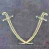
 1545 forum posts 484 photos | And, just to prove that it can be learnt quite quickly, albeit with a fair bit of help, here's a couple of parts I modelled earlier:
From my album, John |
| JasonB | 30/10/2018 16:42:38 |
 25215 forum posts 3105 photos 1 articles | Looking good John, its going to be quite a big engine |
| Neil Wyatt | 30/10/2018 16:50:01 |
19226 forum posts 749 photos 86 articles | Well done John. |
| JasonB | 30/10/2018 17:02:26 |
25215 forum posts 3105 photos 1 articles | As David says there are several ways to end up with the same part, for example the base part in the mag article could have been done with just one sketch that was revolved. Though the way it was built up in the article is a better way to show the absolute beginner the basic first steps. |
| Zan | 01/11/2018 22:35:31 |
| 356 forum posts 25 photos | Assembly problem Items.....A block housing bearing and shaft The housing with a hole is anchored on X..Y plane in X direction A bearing is mated with the shaft Bearing is mated into the block. All looks good Colicky the mouse on any menu or in workspace and the bearing and shaft assembly move out still aligned and mated but always in the same direction, y - Tried several times, same problem any ideas? 2) is it possible to move the position of the tool groups on the main ribbon bar? 3 is the rendering and reflections seen in Alibra’s web site an extra? 4 what will be the actual cost, to buy at the start and will it need an annual subscription? 5) with mirror for a symmetrical component, is there a shortcut to select the whole body having created the first half rather than having to select each feature? Edited By Zan on 01/11/2018 22:38:58 no 5 added
Edited By Zan on 01/11/2018 22:42:45 |
| Lionel Pullum | 02/11/2018 04:51:07 |
| 11 forum posts 1 photos | Just a tip or two on creating custom templates for drawing sheets etc. To create a custom template follow the help file entry "Changing custom templates" to create your version. You are then free to modify this to include what you do and don't need. But the method to create fields in the description block on your drawing as described in the on-line, is not supported in AA3D. Do not despair, you can get around this with a simple copy and paste. Copy and paste a field title, placing it where you want and double clicking on it to edit it to what you want it to say. Then copy and paste one of the predefined fields, e.g. "Sheet scale" to where you want that. Double clicking on this will open the field editing dialog. At the top of this dialog are two radio buttons, "User input" and "Property value", the latter being selected. If you keep it as this you can select what Property value will be automatically writen into the field from the drop down list. If you select "User Input" two fields, the Name of the property you want to add and a suitable input text string. I strongly recommend using Alibre's format of keeping user defined fields in upper case, it helps when you come to fill in the fields, when creating a drawing, to see which fields need your input. And there you are. Save your drawing template, and when you select in when creating a drawing, you will see all of the fields that are contained in your drawing. Now comes the hard part - discipline. When you create a model fill in the Properties dialogs, accessible from the jewel icon, with the info thats important to you, e.g. the material. Then when it comes to creating a drawing of the model most of the fields will be automatically filled for you by magic. Hmm havent worked out how to attach a file or screen dump to this, but when I can I will happily post a simple example
|
| JasonB | 02/11/2018 06:57:05 |
25215 forum posts 3105 photos 1 articles | Zan, 1, First I would align the bore of the block with the outside of the bearing. Then if the bearing is flush with the side of the block align those two, if it sticks out then you can enter a dimension. Next align the bore of the bearing with the OD of the shaft and then use mate or align to set how far you want it to stick out. You will mow be able to rotate the shaft in the bearing but it won't move sideways as you have constrained the sideways positions
2, Leave to David 3. You need the Expert version with Keyshot to render but as mentioned in the article ( i think) Simlab Lite is free. 4.£199 one off or £279 with support in UK or see local agent. 5. David again Edited By JasonB on 02/11/2018 07:04:07 |
| John Hinkley | 02/11/2018 07:28:17 |
1545 forum posts 484 photos | Just to follow up Jason's comment on Simlab Lite (I have no knowledge of this product ), to obtain the rendered images that I showed in my earlier posts, I first scaled the part in the Atom3D window and oriented it how I wanted it to display, then the file was "Export [ed] to PDF" from the File tab. This brings up the picture in your pdf program - Acrobat in my case - a single click on the picture gives a rendered and fully rotatable version. Take a screenshot and clip to the size and content required. A bit long-winded, but it is a work-around and not something I would do on a regular basis. I off to investigate Simlab Lite. John |
| JasonB | 02/11/2018 07:32:02 |
25215 forum posts 3105 photos 1 articles | I export at a STEP file and open that in the rendering prog.That way yo can render individual parts or just one face. |
| David Jupp | 02/11/2018 07:49:02 |
| 978 forum posts 26 photos | Zan, Item 2) - No you can't re-arrange the Ribbon. Item 4) - Atom3D is sold without 'tech support' subscription (except for licensing and activation problems) - this is to keep the cost down. You can choose to pay (or not) a fee for software updates only. The UK re-seller support option is a special to give new users extra assistance if required (totally optional). Item 5) - With FEATURE mirror, you have to select each feature that you wish to mirror (no shortcut for all features so far). PART scale or mirror can mirror the entire part. Note that it behaves differently in that it does not leave the original in place. The 2 mirror functions are used for different tasks. |
| John Hinkley | 02/11/2018 08:10:50 |
1545 forum posts 484 photos | Jason, Yes, I can see that would be an easier way - but my copy of Atom3D only gives the option to "save as" files with a ".AD_PRT" extension. Is this is the only file format that will be available after the trial period? Probably better asked of David Jupp? John |
| David Jupp | 02/11/2018 08:32:34 |
| 978 forum posts 26 photos | John, Try Export instead of Save As - see image. STP, ACIS(SAT) and STL are available.
|
| John Hinkley | 02/11/2018 09:10:36 |
1545 forum posts 484 photos | David, Thank you. Don't know why I didn't think to do that! John
|
| Neil Wyatt | 02/11/2018 12:55:01 |
19226 forum posts 749 photos 86 articles | Two examples: Rendered directly in Alibre by assigning colours , transparency and reflectivity to sketches:
Rendered in the free version Simlab Light. Note I made this as a single part and I haven't got the knack of special colouring in Simlab yet, this was my first try:
|
| Muzzer | 02/11/2018 16:10:36 |
 2904 forum posts 448 photos | Just be aware that when you save in a generic format such as IGS, STP or STL, what you are saving is not parametric ie you can no longer change the dimensions of the model, you lose the design history and often the dimensions are not exactly how you created them. It's possible to use "direct editing" in some programs but you are still not working on or creating parametric models in that mode. Similarly, if you actually found another CAD program that would import native Alibre models (I've yet to find one), you would lose that parametric data, while any assemblies you imported would lose their mates / joints. In the end, when I tried to resurrect previous "orphan" files including Alibre (Geomagic) CAD models, I ended up printing out the 2D drawings and recreating them from scratch in whatever I was using (Solidworks, Inventor, Fusion etc). There's no clever way to do it. Not trying to pee on anyone's parade (accusations of tribalism etc) but be aware that "save as" has distinct limitations as a way to pass models to other systems. Spoken from experience... Murray |
| Rik Shaw | 03/11/2018 12:31:21 |
 1494 forum posts 403 photos | What is the cost of continuing to use the software once the free six months comes to an end.? Rik |


Please login to post a reply.
Magazine Locator
Want the latest issue of Model Engineer or Model Engineers' Workshop? Use our magazine locator links to find your nearest stockist!
Sign up to our Newsletter
Sign up to our newsletter and get a free digital issue.
You can unsubscribe at anytime. View our privacy policy at www.mortons.co.uk/privacy
Latest Forum Posts
- hemingway ball turner
04/07/2025 14:40:26 - *Oct 2023: FORUM MIGRATION TIMELINE*
05/10/2023 07:57:11 - Making ER11 collet chuck
05/10/2023 07:56:24 - What did you do today? 2023
05/10/2023 07:25:01 - Orrery
05/10/2023 06:00:41 - Wera hand-tools
05/10/2023 05:47:07 - New member
05/10/2023 04:40:11 - Problems with external pot on at1 vfd
05/10/2023 00:06:32 - Drain plug
04/10/2023 23:36:17 - digi phase converter for 10 machines.....
04/10/2023 23:13:48 - More Latest Posts...
- View All Topics
Support Our Partners


Shopping Partners
Subscription Offer

Latest "For Sale" Ads
- Reeves** - Rebuilt Royal Scot by Martin Evans
by John Broughton
£300.00 - BRITANNIA 5" GAUGE James Perrier
by Jon Seabright 1
£2,500.00 - Drill Grinder - for restoration
by Nigel Graham 2
£0.00 - WARCO WM18 MILLING MACHINE
by Alex Chudley
£1,200.00 - MYFORD SUPER 7 LATHE
by Alex Chudley
£2,000.00 - More "For Sale" Ads...
Latest "Wanted" Ads
- D1-3 backplate
by Michael Horley
Price Not Specified - fixed steady for a Colchester bantam mark1 800
by George Jervis
Price Not Specified - lbsc pansy
by JACK SIDEBOTHAM
Price Not Specified - Pratt Burnerd multifit chuck key.
by Tim Riome
Price Not Specified - BANDSAW BLADE WELDER
by HUGH
Price Not Specified - More "Wanted" Ads...
Get In Touch!
Do you want to contact the Model Engineer and Model Engineers' Workshop team?
You can contact us by phone, mail or email about the magazines including becoming a contributor, submitting reader's letters or making queries about articles. You can also get in touch about this website, advertising or other general issues.
Click THIS LINK for full contact details.
For subscription issues please see THIS LINK.
Digital Back Issues


Donate

 Register
 Log-in
Model Engineer Magazine
- Percival Marshall
- M.E. History
- LittleLEC
- M.E. Clock

ME Workshop
- An Adcock
- & Shipley
- Horizontal
- Mill

Subscribe Now
- Great savings
- Delivered to your door

Pre-order your copy!
- Delivered to your doorstep!
- Free UK delivery!
All Forum Topics > Model Engineers' Workshop. > Learning CAD with Alibre Atom3D