Forum sponsored by:

Stuart 'No.1' : a beginners tale..
| GaryM | 20/04/2014 12:27:23 |
 314 forum posts 44 photos | Hi Allan, I'm no expert but the steps on the vice jaws are contributing to the problem. My vice just has parallel jaws with no steps or grooves meaning I can use parallels to position work so the milled surface is just above the top of the jaws. Gives a bigger contact area for clamping the work. Just an observastion, without a useful remedy. Gary |
| JasonB | 20/04/2014 13:33:15 |
 25215 forum posts 3105 photos 1 articles | As Gary says using the rebates in the jaws is not the best way with thick parts. Your fairly basic vice will also have a tendancy for the moving jaw to lift as it is tightened more so than a milling vice. If the work is supported by parallels you can tap it down with a lead hammer as you tighten the jaws which will help keep things true. Something like this. You can make do with a couple of strips of steel flat for now if you don't have parallels.
One other thing to watch when first holding castings in teh vice is the surfaces are unlikely to be even or parallel. So its good to use a soft packer between the work and moving jaw so it can take up any irregularities, a scrap of aluminium will do.
When you come to cut the grooves I would use the vice, set the work down low and keep the same side against the vice fixed jaw which will be your ref face and all six grooves can then be cut at the same handwheel setting. Simon's thread shows it here The solder paint will be fine, if you don't know how to tin the parts and then sweat together just ask. I'll look at the conrod drawings later but can't think of anything that needs permanent soldering. J Edited By JasonB on 20/04/2014 13:36:27 |
| GarryC | 20/04/2014 13:34:34 |
 740 forum posts 1043 photos | Hi Gary Yes, the vice is not great, I bought it really with the drill press in mind - I should look at getting a 'precision' milling vice designed for purpose. Top of this years Christmas Wish List now I think.. Hope you are recovering well.. Cheers. Allan. |
| GarryC | 20/04/2014 13:47:13 |
740 forum posts 1043 photos | Thanks Jason, some really good pointers there that I will use... and I will definitely come back when the time comes to ask about using the Solder paint as it will be another 1st for me... Back now to my facing off's... Cheers. Allan. ps. Simon's thread / work - superb! Edited By Allan. on 20/04/2014 13:55:43 |
| GarryC | 23/04/2014 13:48:43 |
740 forum posts 1043 photos | Little time unfortunately over the Bank Holiday to make progress, but I do have the bottom bearing 'blocks' faced to size and ready for the channels to be milled now. The reason for this post though is I've been trying to find some guidelines on sizes to aim for when making parts for fitting to another. e.g. How much undersize for a Push Fit, Close Fit, Sliding Fit, Interference Fit etc. I was hoping to find a 'basic' chart to use as a guideline but all I've found so far are charts with masses of numbers to include tolerances for the parts themselves. Does anyone have by chance a link to something simple. Feels like something it would be useful to have at least some idea on...! The Bottom Bearings here I assume I would make as a close fit into the housing blocks, it would save time etc to have a target size to aim at.. Hope its not a dumb question. Maybe there are no simple guidelines..? Thanks anyway for anyone that does have a link or some info... The bottom Bearing 'blocks' ready for Milling the channels..
Regards Allan. Edited By Allan. on 23/04/2014 13:55:04 Edited By Allan. on 23/04/2014 14:00:44 |
| Neil Wyatt | 23/04/2014 16:01:25 |
 19226 forum posts 749 photos 86 articles | There is a useful table in Tubal Cain's The Model Engineer's Workshop Handbook giving 12 classes of fit from shrink to large clearance. Neil
|
| GarryC | 23/04/2014 16:44:38 |
740 forum posts 1043 photos | Great thanks Neil, that sounds to be exactly what I'm looking for.. Cheers. Allan. |
| GarryC | 26/04/2014 12:16:45 |
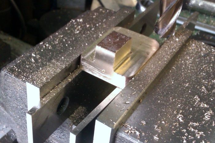
740 forum posts 1043 photos | Have one of the 'bottom bearing half's' fitted into the housing now.. Finding this an interesting little job and much more work than I first imagined, mainly due to my bad technique though I expect - there was nothing really like this with Victoria - fitting bearings to a housing. After marking out I used a 12mm end mill down the centre and across the 3 sides followed by a 14mm end mill - all with the mill table locked in the same position, then final fitting with some slight work with a file.. Both bearings done separately (I'm halfway through the second) - but with the same mill settings.. It's a first attempt at something like this and far from perfect, but the bearing is a nice tight fit and feels very solid with no movement... Test fitting one of the bottom bearing half's 1.
Test fitting one of the bottom bearing 'half's' 2.
Test fitting one of the bottom bearing 'half's' 3.
Regards Allan. |
| GarryC | 26/04/2014 12:56:52 |
740 forum posts 1043 photos | For the sake of completeness - forgot to include the setup used on the mill for the channel...
Regards. Allan. Edited By Allan. on 26/04/2014 12:57:27 |
| GarryC | 28/04/2014 11:53:31 |
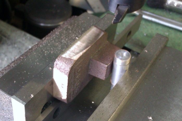
740 forum posts 1043 photos | Both the bottom bearing half's in the housings now. Next the top half's which I need to temporally solder together to turn on the lathe. Test fitting the bottom bearing half's. Think I did a slightly better job on the second one - which is as it should be second time around, but both seem to fit ok and feel solid with no movement.. The second one done is on the right in the photo..
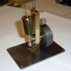
My new 'very basic' soldering kit. Not much idea how to use it yet.... I wanted to ask if it's just a matter of applying the solder paint on both surfaces of the 2 'top bearing half's', clamping together and heating? Do I need to heat from both sides or can I just lay them on the vermiculite fire brick without moving, (have more than one of these bricks of course..)? I assume I just heat up afterwards to separate and wipe the surfaces off while hot, do I need a solvent for this?. Do I need to wait long after cooling before I can put it in the Lathe or do they have to be left to stand... How hot do I heat? Sorry lots of questions there - but thanks to anyone for any pointers, even one or two would be a great help..
Regards Allan. ps. won't do it next to the straw of course.. |
| roy entwistle | 28/04/2014 13:09:39 |
| 1716 forum posts | Alan I would think that you need to machine the bottom of the top half of the bearings and then solder one top to one bottom and then machine that I would also mark each pair so that they go together as a pair and the right way round if that makes sense Roy Edited By roy entwistle on 28/04/2014 13:11:47 |
| roy entwistle | 28/04/2014 16:09:59 |
| 1716 forum posts | Alan I may have jumped in with both feet there I now assume that you intend sweating the two top halves together so that you can bring to width (7/8" Are tops of the lower bearings flush with where the top caps sit they will need to be Roy Edited By roy entwistle on 28/04/2014 16:11:15 |
| Andrew Johnston | 28/04/2014 16:22:56 |
 7061 forum posts 719 photos | The method of sweating bearing halves together before machining the bore has never worked for me; the joint just isn't strong enough. I much prefer to make a simple jig to hold the bearing halves, like this:
As a bonus you don't muck up a nice machined finish by heating the bearings up twice. Andrew |
| JasonB | 28/04/2014 16:48:15 |
25215 forum posts 3105 photos 1 articles | I think sweating will be OK in this case as you don't need to machine the outside and there is a large area for the solder to stick to. First machine the underside if the castings so you have a good smoothe surface to solder. Apply a light coat of solder paste to both surfaces and heat, you will see the flux bubble off and the grey liquid turn to silver when the temp is right. Now take acotton rag (not manmade as it melts" and wipe the surface to remove any excess solder.) These are two parts that have been tinned
As you are using paint this is probably the best way to continue, allow to cool. Then apply a little more paint to one face this will provide some flux, place the other half ontop and then heat until you see the solder flow, give a gentle push together to expell any excess solder and leave to cool. Then into the 4 jaw to face one side does not have to be spot on. Once you have a clean face accurately mark the centre point, you should be able to see a faint line where the solder joint is so the centre should be along this line. Set it back up in the 4 jaw and get your punch mark to run true, Face back to width and machine the 1" OD. Turn round in the chuck and do the same on the other side. Drill the two mounting holes then heat to seprate the halves, rub on a sheet of Emery to remove any solder and then bolt to the casting to bore between centres. |
| GarryC | 28/04/2014 19:10:29 |
740 forum posts 1043 photos | Hi Roy Thanks, sorry, I should have explained a little more to make what I intended to do clearer - yes you are quite right in your second post, and there is as you say quite a bit of cleaning up with the file to do first - seems crazy to me now looking back at how I thought I could avoid the file - quite enjoy using it these days and can certainly see how important it is to be able to have at least some skills with. The bottom bearing half's are flush with the tops of the housings. Hi Andrew Thanks, the jig looks like a great way to hold the two half's - also pleased to say I can understand how it works from your photo as well..! I'm still short of 'stock' material for things like that but also at the moment with the little Lathe etc would likely take quite a while to do. It will be great to have a go at though when I have upgraded - definitely remember that one I'm sure it will come in useful.. Still regretting not going for larger with my 'first' Lathe.. Hi Jason Thanks, that's a great step by step to be able to print off and follow for this now. Glad I waited to post here first otherwise I would have definitely gone about it the wrong way.. Making a start with it in the morning.. and its good to be having a go and finding out about some soldering techniques.. Cheers all. Allan.
|
| roy entwistle | 29/04/2014 10:25:32 |
| 1716 forum posts | Alan When youv'e got the two top bearing caps soldered together DO NOT bore the 1/2" hole for the crank shaft Remember that the cap is only half of the bearing the other half is the bottom Top and bottom should be bored together Roy ( Does this make sense ? ) |
| GarryC | 29/04/2014 10:53:07 |
740 forum posts 1043 photos | Hi Roy Thanks very much, really appreciated - its great to have input like that. In this case though yes I did know not to do that. Hope you will continue to follow and if you do please let me know again if you see any problems I may get into. In having breakfast now but have been busy filing earlier. I won't go on about it in case it makes me look totally mad, but the filing has really clicked this morning and its been brilliant. The 'lumps' on the end of the top bearing half's needed lots of filing around the 'curve' and 'rubbing' the file around there has given me a new insight - what a great feeling... My distant Grandfathers were from a line of Stone Mason's and another Grandfather line were Blacksmiths - I couldn't help wonder this morning if there might be some hope for me yet! Thanks again Roy. Allan. |
| GarryC | 29/04/2014 15:01:19 |
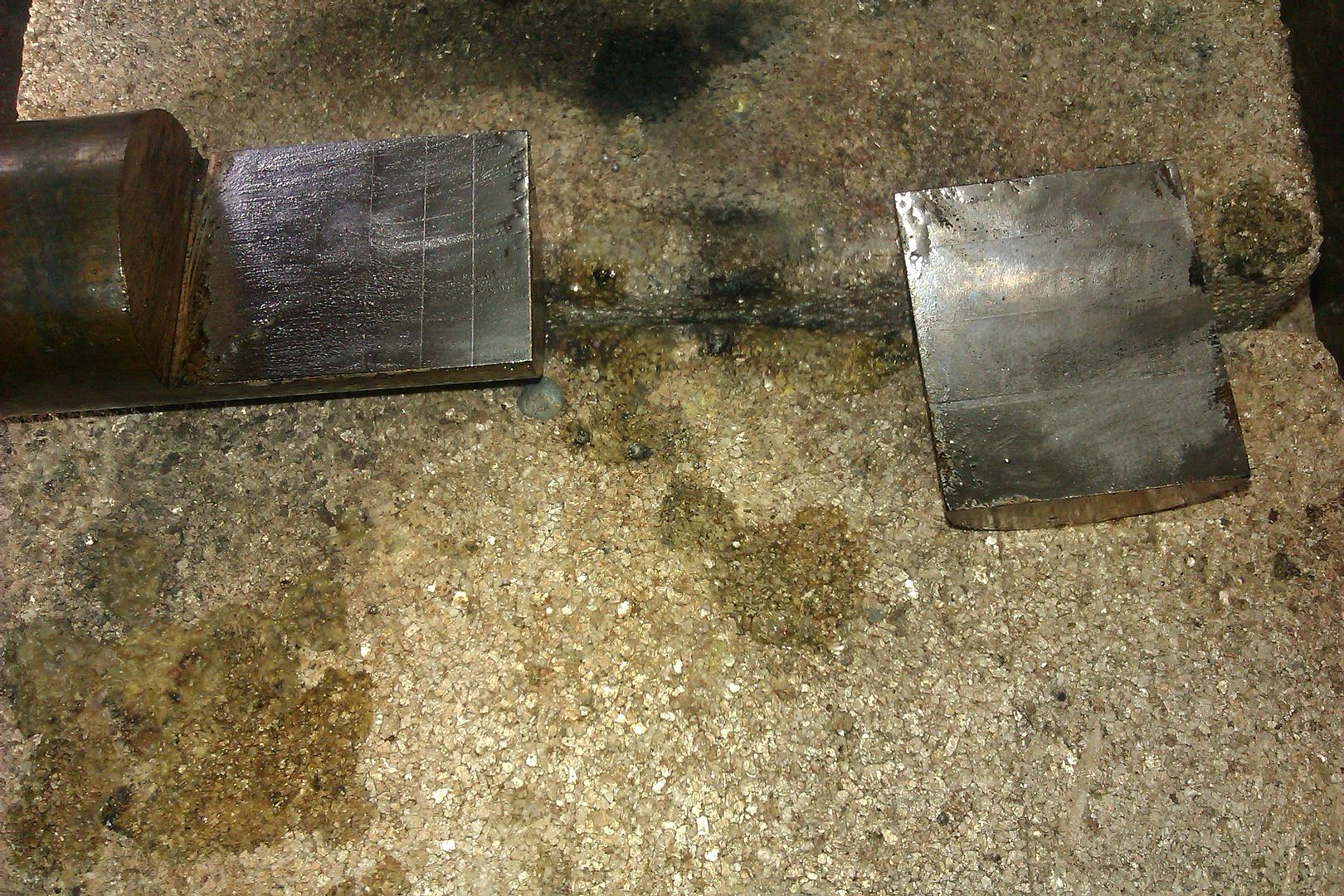
740 forum posts 1043 photos | Didn't get to make as much progress as I thought I would this morning but am now at the point of being ready to solder. Just managed to clean up the 'top bearing half' castings and faced the surfaces ready for soldering. Had some strange marks though left on the surfaces afterwards that I haven't seen before... The top bearing half castings after cleaning up with the file. They took quite a bit of filing.
Setting up to face the bottom surfaces.
I only took a light skim off ready for soldering, 3 thou at 380 rpm, maybe I should have taken off more, or I'm using the wrong speed (they are Gunmetal). I don't know if these marks were already there under the surface or the tool was digging in. The carbide insert has I suppose done a lot of work, may need changing, but it looks ok under a 'glass', like new in fact - there was absolutely no sign from the lathe when facing that there was anything untoward happening - bit of a mystery to me. As the surfaces are completely flat and I will be boring through most of it shortly rather than take any more material away I thought it would still be ok for temporary soldering and plan to go ahead like this - unless anyone is kind enough (if thought necessary) to advise me otherwise that is..
Regards. Allan. |
| Andrew Johnston | 29/04/2014 15:18:42 |
7061 forum posts 719 photos | If you mean the small indentations, they look like inclusions in the casting to me, possibly caused by gassing. They will mostly disappear when the bearings are bored, but if there is enough allowance on the casting I would have been inclined to take a bit more than 3 thou off. Regards, Andrew |
| GarryC | 29/04/2014 16:02:44 |
740 forum posts 1043 photos | Thanks Andrew, that would seem to make sense to me i.e.. that they were there beforehand, one of them in particular is quite deep and as I said the Lathe made no sign of any problem. Interesting, its the first time I've seen anything like that after machining. Agree as well I should have taken a bit more off... Cheers. Allan. Edited By Allan. on 29/04/2014 16:04:46 |


 and face the ends in the lathe that's ok but it looks to me as if there is a lot cleaning up with the file to be done


This thread is closed.
Magazine Locator
Want the latest issue of Model Engineer or Model Engineers' Workshop? Use our magazine locator links to find your nearest stockist!
Sign up to our Newsletter
Sign up to our newsletter and get a free digital issue.
You can unsubscribe at anytime. View our privacy policy at www.mortons.co.uk/privacy
Latest Forum Posts
- *Oct 2023: FORUM MIGRATION TIMELINE*
05/10/2023 07:57:11 - Making ER11 collet chuck
05/10/2023 07:56:24 - What did you do today? 2023
05/10/2023 07:25:01 - Orrery
05/10/2023 06:00:41 - Wera hand-tools
05/10/2023 05:47:07 - New member
05/10/2023 04:40:11 - Problems with external pot on at1 vfd
05/10/2023 00:06:32 - Drain plug
04/10/2023 23:36:17 - digi phase converter for 10 machines.....
04/10/2023 23:13:48 - Winter Storage Of Locomotives
04/10/2023 21:02:11 - More Latest Posts...
- View All Topics
Support Our Partners


Shopping Partners
Subscription Offer

Latest "For Sale" Ads
- Reeves** - Rebuilt Royal Scot by Martin Evans
by John Broughton
£300.00 - BRITANNIA 5" GAUGE James Perrier
by Jon Seabright 1
£2,500.00 - Drill Grinder - for restoration
by Nigel Graham 2
£0.00 - WARCO WM18 MILLING MACHINE
by Alex Chudley
£1,200.00 - MYFORD SUPER 7 LATHE
by Alex Chudley
£2,000.00 - More "For Sale" Ads...
Latest "Wanted" Ads
- D1-3 backplate
by Michael Horley
Price Not Specified - fixed steady for a Colchester bantam mark1 800
by George Jervis
Price Not Specified - lbsc pansy
by JACK SIDEBOTHAM
Price Not Specified - Pratt Burnerd multifit chuck key.
by Tim Riome
Price Not Specified - BANDSAW BLADE WELDER
by HUGH
Price Not Specified - More "Wanted" Ads...
Get In Touch!
Do you want to contact the Model Engineer and Model Engineers' Workshop team?
You can contact us by phone, mail or email about the magazines including becoming a contributor, submitting reader's letters or making queries about articles. You can also get in touch about this website, advertising or other general issues.
Click THIS LINK for full contact details.
For subscription issues please see THIS LINK.
Digital Back Issues


Donate

 Register
 Log-in
Model Engineer Magazine
- Percival Marshall
- M.E. History
- LittleLEC
- M.E. Clock

ME Workshop
- An Adcock
- & Shipley
- Horizontal
- Mill

Subscribe Now
- Great savings
- Delivered to your door

Pre-order your copy!
- Delivered to your doorstep!
- Free UK delivery!
All Forum Topics > Work In Progress and completed items > Stuart 'No.1' : a beginners tale..