Forum sponsored by:

supercharged V12 2 stroke
Methanol burning beast!!
| Jens Eirik Skogstad | 21/12/2013 15:33:16 |
 400 forum posts 22 photos | As the picture of the difference 2 stroke engines is showing clearly the pressure in cylinder will be disappeared after the transfer port is closed while the exhaust port is still open, "Supercharging" is incorrect to use in 2 stroke engine. Also we will call it for blower/scavenge blower instead "supercharger". 4 stroke engine with supercharger will give more power due there is enough pressure in cylinder before compression stroke begins. |
| Muzzer | 21/12/2013 18:27:50 |
 2904 forum posts 448 photos | Yes, you can't really "supercharge" a 2-stroke even with exhaust valves and proper injection. The blowers and turbochargers are primarily to ensure scavenging. However, when you have a V engine like this, you aren't going to get any effective crankcase pressure when you need it, so the transfer ports aren't going to do much for you. The use of a supercharger (scavenge pump?) is probably a sensible choice here, given that Dean is aiming to get this impressive beast working. At least there is a decent chance of the cylinders getting some mixture........as he explained back on the 8th. Is this a CI (diesel) or will it have spark plugs? That's a lot of parts either way! Good luck, lots of people watching and wishing you well - no pressure, then!! It'll make a fantastic noise / smell.... Edited By Muzzer on 21/12/2013 18:28:33 |
| dean clarke 2 | 21/12/2013 23:59:36 |
 169 forum posts 330 photos | Hi guys and thanks for the comments and info etc. Hi jen, I accept what you are saying about 2 strokes with the port timing etc, and if you want to call it a scavenge pump then thats fine with me, each to his own, i will use the term supercharger as it will be forcing more mix into the engine than could otherwise be done. however without going into too much detail (secret squiral suff etc) LOL. the engine is arranged with porting and exhaust dimensions to allow some amount of positive charge in the combustion chamber, this is managed by using the rather large expansion pressure of combustion to act as a back door as it escapes out the exhaust system to allow positive transfer pressure to reach the combustion chamber. it is somewhat more involved than what i've just said but it does work. there are a few variables that need a bit more experimentation to finalise as it becomes a balancing act of appropriate pressures which will dictate drive speeds etc. Oh well i guess thats all for now will keep you all posted on the progress. The exhaust back pressure is also what helps stop excessive fuel consumption to a certain extent. cheers for now dean p.s. before anyone asks i have done some experiments and yes the theory is sound and will run, actually it will run very well i think but like my nanna always used to say " the proof is in the pudding" so we shall see. |
| dean clarke 2 | 22/12/2013 00:01:25 |
169 forum posts 330 photos | Oh yea sorry i forgot to answer you muzzer, this is a glo engine running on methanol and nitro methane with a bit of good ole caster oil to stop the welding of internal parts. dean |
| Doubletop | 22/12/2013 07:05:24 |
 439 forum posts 4 photos | Posted by dean clarke 2 on 21/12/2013 23:59:36:
" the proof is in the pudding" so we shall see.
Can't wait; and with the progress so far I can't see us having to wait until until Christmas 2014 for the pudding One of the many watching with interest.... Pete Edited By Doubletop on 22/12/2013 07:09:19 |
| dean clarke 2 | 28/12/2013 03:04:13 |
169 forum posts 330 photos | Ok so a quick update to let you know where I'm up to. I have made the fixture to turn the crank big end journels and found a slight problem, the fixture, with the crank in, was too big for the inside dia of my 3 jaw chuck. bugga!! now what to do. Luckily i have a larger 4 jaw self centering chuck so with a slight modification with a boring bar i can now machine the big ends, yay!! So i am now in the middle of making the tools to turn the journels. will post the photos if all goes well, maybee in the next few days depending on how much shed time my wife lets me have. LOL. cheers for now dean Edited By dean clarke 2 on 28/12/2013 03:06:20 |
| David Tweddle 1 | 28/12/2013 14:10:05 |
| 3 forum posts | Hi Dean if you need a test bed to run it in, my 72" Piper Cub is nearly completed and needs a decent power unit. Keep up the brilliant work and I will sit back and learn from a true maestro . Regards David |
| dean clarke 2 | 01/01/2014 05:52:09 |
169 forum posts 330 photos | LOL yea sure no problem David just cruise on down to cambridge N.Z and we'll bolt it in. I was thinking that I might actually build an ME 109 to put it in, control line of course, about 76" span, what do you think? LOL. Hopefully i will have the crank finished tonight. I am in the middle of building a custom tool post for the lathe to eliminate the toolpost flex from the standard (not very ridged) toolpost. I knew i should have got the bigger lathe. oh well. will post the photo update later tonight all going well dean |
| Doubletop | 01/01/2014 06:06:04 |
439 forum posts 4 photos | Dean Cambridge NZ? That means there is some chance of seeing this creation in the flesh. ME109 or just on the bench Pete (Wellington NZ) |
| dean clarke 2 | 01/01/2014 07:14:52 |
169 forum posts 330 photos | Sure mate no problem, just drive on up, send me a p.m. i'll give you my contact details etc, lets arrange to hook up and have a show and tell. i have a few models (all c/l) and a few engines too. could run the v8 up again too. now off too the shed to finish this tool post and get the blimmin crank done, really want to see it finished tonight!! dean Edited By dean clarke 2 on 01/01/2014 07:15:36 |
| dean clarke 2 | 01/01/2014 16:33:05 |
169 forum posts 330 photos | WELL I finally got the big ends all finished, Wot a saga!!! well got the late afternoon and all night,way into the early just before sunrise time, in the shed and was able to get the tooling and problems solved for the big end journel turning and finishing setups. below is a group of photos showing the tools and set ups i used to turn and finish grind and polish all the big end journels. next mission is the same treatment for the mains and the final champhering and polishing. here's the end result.....................
here's the tooling etc
|
| dean clarke 2 | 01/01/2014 16:34:13 |
169 forum posts 330 photos | Actually............here's the tooling etc
here's the nibbling of the journels being done
here's the flywheel faces being machined and radiuses applied to journel corners
so here's the fixture with the finished crank........
sorry but i forgot to take a photo of the grinder setup, but here's a close up of the finished big end journels
So i will now go and get a few hours sleep and hopefully be up before my wife gets home, later today, and get the main bearings all finished as well. that would be just fantastic!!!!! ny nyz all (briefly anyway). lol dean
Edited By dean clarke 2 on 01/01/2014 16:45:24 Edited By dean clarke 2 on 01/01/2014 16:46:07 Edited By dean clarke 2 on 01/01/2014 16:50:10 |
| Stub Mandrel | 01/01/2014 19:35:05 |
 4318 forum posts 291 photos 1 articles | I hate it when people's jigs and fixtures look better than my finished work... Neil |
| dean clarke 2 | 04/01/2014 04:36:23 |
169 forum posts 330 photos | Well here's the finished crank, YAY!!!!!!!!!!!!!!!!!!
now its onto the next parts, carbys i think cheers for now dean |
| dean clarke 2 | 10/01/2014 08:14:18 |
169 forum posts 330 photos | Well been very busy this last week, unfortunately just not in the engine build department. I have been able to start the cylinder fin and head blocks. There is also a photo showing the crank finished and fitted to the block.
Off on holiday for 2 weeks now so wont be back in the shed till we get home, will upload the progress shots for the heads etc when they are all done. cheers dean |
| dean clarke 2 | 28/01/2014 08:20:47 |
169 forum posts 330 photos | well, home again after a lovely trip to Aussie,Gold Coast with theme parks galor. Unpacked my bag and straight back into the shed to continue working on the 2 cylinder fin and head blocks. these are machined and drilled as one piece and then separated, surfaced and then bolted to the engine block and the cylinder bore holes machined in situ. here are some photos of the progress so far. dean
will post the rest of the photos in a little while, duty calls cheers for now dean |
| Michael Gilligan | 28/01/2014 08:49:37 |
 23121 forum posts 1360 photos | Dean, Nice work with that Slitting Saw !! MichaelG. |
| dean clarke 2 | 28/01/2014 21:44:03 |
169 forum posts 330 photos | Hey thanks had a bit of practice i must admit. here are a few more photos of the next stage of the fin/head block machining cheers dean
the pilot holes were drilled 10mm then milled to 12mm for the glo plug clearance.
next step is to set the cylinder heads and fin blocks up bolted together to the engine block and machine all the external shapes,ports and fins. will upload these later tonight. cheers for now dean Edited By dean clarke 2 on 28/01/2014 21:45:16 Edited By dean clarke 2 on 28/01/2014 21:48:00 |
| dean clarke 2 | 02/02/2014 00:17:24 |
169 forum posts 330 photos | So it has been a very busy time in the shed lately, have managed to make and finish all 12 cylinder liners, all thats left to do to them is hone and polish with diamond lapping. I have also managed to machine the transfer ports into the cylinder fin blocks and machine the external profile shape to the heads and fin blocks
Next step is the machining of the exhaust ports and fins into the cylinder fin blocks. i will upload the photos as soon as i have finished this last step. I think i will tackle the elbow exhaust stubs after these are finished. Cheers for now Dean Edited By dean clarke 2 on 02/02/2014 00:18:08 |
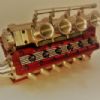
| dean clarke 2 | 07/02/2014 21:38:30 |
169 forum posts 330 photos | Well I have finally finished all the exhaust stubs, what a mission! This step of the build was probably the most challenging for me in many ways as I wanted to have the typical aero v12 looking stubs, but how to do that without castings. So i machined a bar stock to the top view profile and then cut off the correct number of biscuit slabs. These were then set up in the mill after marking out all the relevant dimensions for drilling the internal holes. The first slab was set up to a jig formation and the others just inserted to repeat the process. This saved a great deal of set up time as i had to do it only once for each step. Once both holes were drilled I made a mandrel to mount the stubs on for turning both ends. When all the lathe work was completed I then finished them off with a file to final shape and cleaned up with emery tape. here are some photos of the parts etc
So next its onto machining up the split main bearings and backplate along with the prop driver and spinner nut. This will complete the bottom end of the engine. Cheers for now Dean |


Please login to post a reply.
Magazine Locator
Want the latest issue of Model Engineer or Model Engineers' Workshop? Use our magazine locator links to find your nearest stockist!
Sign up to our Newsletter
Sign up to our newsletter and get a free digital issue.
You can unsubscribe at anytime. View our privacy policy at www.mortons.co.uk/privacy
Latest Forum Posts
- hemingway ball turner
04/07/2025 14:40:26 - *Oct 2023: FORUM MIGRATION TIMELINE*
05/10/2023 07:57:11 - Making ER11 collet chuck
05/10/2023 07:56:24 - What did you do today? 2023
05/10/2023 07:25:01 - Orrery
05/10/2023 06:00:41 - Wera hand-tools
05/10/2023 05:47:07 - New member
05/10/2023 04:40:11 - Problems with external pot on at1 vfd
05/10/2023 00:06:32 - Drain plug
04/10/2023 23:36:17 - digi phase converter for 10 machines.....
04/10/2023 23:13:48 - More Latest Posts...
- View All Topics
Support Our Partners


Shopping Partners
Subscription Offer

Latest "For Sale" Ads
- Reeves** - Rebuilt Royal Scot by Martin Evans
by John Broughton
£300.00 - BRITANNIA 5" GAUGE James Perrier
by Jon Seabright 1
£2,500.00 - Drill Grinder - for restoration
by Nigel Graham 2
£0.00 - WARCO WM18 MILLING MACHINE
by Alex Chudley
£1,200.00 - MYFORD SUPER 7 LATHE
by Alex Chudley
£2,000.00 - More "For Sale" Ads...
Latest "Wanted" Ads
- D1-3 backplate
by Michael Horley
Price Not Specified - fixed steady for a Colchester bantam mark1 800
by George Jervis
Price Not Specified - lbsc pansy
by JACK SIDEBOTHAM
Price Not Specified - Pratt Burnerd multifit chuck key.
by Tim Riome
Price Not Specified - BANDSAW BLADE WELDER
by HUGH
Price Not Specified - More "Wanted" Ads...
Get In Touch!
Do you want to contact the Model Engineer and Model Engineers' Workshop team?
You can contact us by phone, mail or email about the magazines including becoming a contributor, submitting reader's letters or making queries about articles. You can also get in touch about this website, advertising or other general issues.
Click THIS LINK for full contact details.
For subscription issues please see THIS LINK.
Digital Back Issues


Donate

 Register
 Log-in
Model Engineer Magazine
- Percival Marshall
- M.E. History
- LittleLEC
- M.E. Clock

ME Workshop
- An Adcock
- & Shipley
- Horizontal
- Mill

Subscribe Now
- Great savings
- Delivered to your door

Pre-order your copy!
- Delivered to your doorstep!
- Free UK delivery!
All Forum Topics > I/C Engines > supercharged V12 2 stroke