Forum sponsored by:

A Challenge - How Would You Machine This Part?
| Andrew Johnston | 05/06/2011 22:51:51 |
 7061 forum posts 719 photos | And so to the delicate task of replying to JasonB and mgj. I hope you don't mind me making it a combined reply. I am fully aware that the differential gears in full size are 'as cast' and that they are slow moving and lightly loaded. I suspect that at the time it would have been pretty difficult, and very expensive, to get bevel gears machined. I believe that the Gleason bevel planer was invented in 1874, but I assume it took quite a while to cross the Atlantic, and become established. I hadn't thought of having the gears cast, although it would have been an interesting exercise. Of course in order to make the patterns I would have had to go through the same design process, which is what took most of the time! mjg - Well why not?! I could have made the bevels by the parallel depth method and as mentioned I did do all the calculations for a range of pinion and crown wheel sizes to get ODs that were a close match to the existing drawings. However it would have still involved quite a lot of work in re-designing other parts and ensuring that they still fitted together. I must be slow, because I'm sure I couldn't do the necessary calculations in 5 minutes, and it would take me longer that three nights to do the machining. As an aside I am actually building two engines, and this design has three pinions in the differential, not two. So that's six pinions and four crown wheels. There are some things in mjg's post I don't follow. What are the advantages of parallel tooth bevels? Errr, I thought that was exactly what my method did do, it makes the gears from a standard length of bar? I don't follow the reasoning for using a vertical mill, surely a horizontal mill would be easier? Lastly I don't understand why more than one arbor would be needed. I only used one arbor to make the pinions, took me about half an hour to make. It doubles up for use in the lathe to make the initial blanks, on the mill to cut the teeth, and back on the lathe to finish the front and back chamfers. I have a vertical mill, a horizontal mill, a CNC mill and a universal dividing head, so I could have chosen any of the methods mentioned. I've even got a hacksaw and round file, but not the patience! After a lot of thinking and designing, and false starts, I did it the way I did because it was a challenge, I'm interested in the design and manufacturing process. I feel that I now know a lot more about the way bevel gears are designed, the mathematics of involute curves and the tooth shapes and how to calculate them, and the means of making the gears, including the approximate methods. At the end of the day, each to his own, and good luck to them. Regards, Andrew PS: Did you know that the use of the involute curve of the circle was first suggested for use in gears by Euler? |
| Steve Withnell | 05/06/2011 22:52:36 |
 858 forum posts 215 photos | Posted by Andrew Johnston on 05/06/2011 10:45:21:
Steve: Wow, nice looking gears! I may be asking you for advice in the future; there are two bevel gears needed for the governor on my traction engines. I think they're about 20DP so milling by the CNC route will need a small cutter. So I may use the parallel depth method for them. Just one comment; the space between the teeth on the two gears to the left seems quite deep in relation to the tooth width. Is this a consequence of the parallel depth method?
Regards,
Andrew
I don't know! (might be I cut a bit too deep!) Here is the spreadsheet I used to design them: I built it originally from the Ivan Laws book, then made some mods based on Franklin Jones.
|
| Andrew Johnston | 05/06/2011 22:58:15 |
7061 forum posts 719 photos | JohnS, Presumably the dividing head still needs to be driven by a stepper motor? I do have a universal dividing head, but it is not motorised. Regards, Andrew |
| mgj | 06/06/2011 17:58:54 |
| 1017 forum posts 14 photos | Andrew- of course, if one wants to, and I did make that point. But turning these things out in ali first to make a pattern for a set of true bevels seems a very long and relatively expensive way around the houses. Further, the earlier part of this thread created an impression (to me) that one needs to go to such lengths to make a set of diff gears for a TE, when actually one does not, and a very satisfactory set of gears can be knocked out with the much more common vertical mill and some kind of indexing head. I just had the impression that perhaps the approach was more how to make a set of true bevels, when possibly a more holistic view - how to make a satisfactory TE diff might have advantages. |
| JasonB | 06/06/2011 18:05:32 |
 25215 forum posts 3105 photos 1 articles | I don't think Andrews intension is to use the alloy ones as a pattern, I feel he was just testing the programme on alloy and will machine the final ones from CI bar.
A horizontal miller is obviously the better machine for the job as it will be a lot more rigid when you get upto 6DP but not many of us have one which is likely why mgj suggested a vertical setup. You cab also use a rotary table and index plates with a vertical mill as the TR can just be skewed round to the required angle.
J Edited By JasonB on 06/06/2011 18:27:03 |
| Richard Parsons | 06/06/2011 18:26:19 |
 645 forum posts 33 photos | Anderw In the Hiraoka Climax locomotive the author scratch builds everything (even the wheels). From his writings I understand he has only a lathe, a vertical mill (perhaps) and a pillar drill. His bevel gears have an offset axis. That is the two shafts by pass each other at right angles. He describes not only the tooling, the main parts of which are the ‘wedge’ which sets the bevel angle, the work piece carrier which doubles as dividing head, but also the cutters and how to make them (the way he does this needs no backing off!). His gauges are very simple. As you have a Cleaver Number Contraption (CNC) then OK use it. He does it all by ‘Mandraulic methods and has FUN, but you take half the time (and can drink tea whilst the machine works for you. When I am cutting a slice oh a bit of real railway rail (the only source of good steel I have) I enjoy listening to a strongman sawing (my power saw) whilst I contemplate a large mug of Rosie and a Zemle es Lekver – a jam roll-. Good luck Dick Edited By Richard Parsons on 06/06/2011 18:27:16 |
| mgj | 06/06/2011 19:09:05 |
| 1017 forum posts 14 photos | Jason - I thought they were to be cast, but it could be a mix up in terminology. I agree about the milling machine - I did my 8DP gears on a Dore Westbury, the largest being about 9" in dia. 6DP will be a bit of a shaker - which is one reason why on my vertical mill I got one that would do a sensible bottom speed (54 RPM IIRC) and not the 100+ rpm that many machines will do. A horizontal would be better, but if one gets the head down and keeps the quill extension to a minimum it will be fine (but I'm not using a DW for the 4" engine!) To finish really. Were I building a gunsight with zero backlash and all then 'd specify true bevels and all. When I built the DW, Quorn and GHT dividing head, then setting to .0002" was normal (and boring and painful) for certain bits. But when one is building a TE, and one is struggling to keep the hornplates more or less flat after all that riveting, and they are what carries crank and 2nd motion shafts, the gears will fit where they touch, like it or not! And especially if it is a road locomotive with springs and the axle is moving around! Edited By mgj on 06/06/2011 19:11:11 |
| John Stevenson | 06/06/2011 19:31:15 |
 5068 forum posts 3 photos | These were traction engine bevels true but it's the learning curve that matters, the next job could be a set of camshaft gears to a DOHC engine or perhaps cast gears are good enough here ? Remove the blinkers. [EDIT] Giles Parkes ran me up tonight, now Giles is 138 years old and dead set on cutting gears the old fashioned way, no CNC for Giles. However the reason for the phone call was he's been thinking [ good pastime that ] and wanted to know if with the correct programming the CNC could put spiral gashes into a hob blank and then go on the generate the hob teeth WITH relief, all at one go. I must admit I had never thought of this and yes it can be done which would make a very accurate hob without all the banging that occurs with the backing off process. Helical gashed hobs will also cut smoother . Nice one Giles, proves at even at 138 he can still see the curvature of the earth. John S. Edited By John Stevenson on 06/06/2011 19:37:29 |
| JasonB | 06/06/2011 19:42:25 |
25215 forum posts 3105 photos 1 articles | Pic of a set of embrio pinions from a full size Fowler resteration may be of interest, From the machining marks I would assume they were done by CNC.
 However the holes for the pinion pins were very definatly done using manual methods
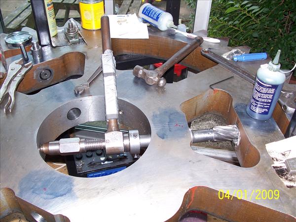 Photos taken from Carl's Fowler A4 rebuild on TT forum Edited By JasonB on 06/06/2011 19:49:01 |
| Andrew Johnston | 06/06/2011 22:40:54 |
7061 forum posts 719 photos | There definitely appears to have been some confusion here. It was never my intention to make castings from patterns; indeed I hadn't even thought of castings until it was mentioned by Jason.It's an interesting thought though! Jason is also quite correct in stating that I am machining in aluminium simply to check the G-code and learn about stepover values versus surface finish. At some point even I stop thinking and do some experiments. Aluminium is cheap and readily available (here I apologise to Richard P) whereas I will have to order cast iron specially, and the real crown wheels are actually castings with other features attached. It was never my intention to suggest that all this effort was needed to make gears for a traction engine differential. That is why the purpose of the gears wasn't mentioned in the original post. In fact the post was originally intended to be a gentle nudge to the 'no CNC' protagonists. May be it is fortunate that it has morphed into something else. My horizontal mill was a snap decision buy, on offer from a model engineering tool dealer (not normally noted for cheap prices) at a knock down price. I assume they'd got a job lot from a college, and, since it is a larger machine than might normally be found in a home workshop, they just wanted to move them on. It cost more to have it delivered than the mill itself cost. So far I haven't even managed to get the motor to change note, let alone struggle. I've cut all the pinion gears for the traction engines on it, 6DP in EN8 and 5DP in cast iron, in one pass, with not even a cough from the motor. Interesting pictures posted by Jason. The bevel pinions must have been CNC'd, difficult to see how else it could have been done given that the teeth are effectively pockets. It looks like the stepover used was radial rather axial. I chose axial, as then at least the machining marks are parallel to the line of contact. Wow, it must have taken ages to machine the holes for pinions by handraulic means. I wonder how the pockets for the pinions were done, doesn't look machined, but too clean for flame cut, laser or water jet maybe? Ah, now JohnS has opened another whole can of worms. I was only thinking earlier this evening, while weeding one of the fruit bush areas in the garden, about the steering worm and wheel for the traction engine. I have seen a worm, machined by CNC, at my supplier, and frankly it looked a little rough, I could do better! But I may well end up machining the worm (two start) by manual means. But what about the worm wheel. My supplier, in common with others I expect, simply uses a helical spur gear. Perfectly adequate for the job of course. But, being obtuse, I wondered if I could machine a proper worm wheel. I have the kit to do it, if I had the necessary hob. The question then becomes could I machine a suitable hob, with relief, on the CNC mill? Watch this space. Regards, Andrew |
| mgj | 06/06/2011 22:52:57 |
| 1017 forum posts 14 photos | Rarely have I had the privilege of reading so much twaddle about over-engineering a component for an unstressed rustic device. And as for blinkers- thank you but I have done my share with cogs. Real ones for racing engines, and tank turret fire control systems. And on that note may I bid you all a very fond farewell |
| John Stevenson | 06/06/2011 23:11:52 |
5068 forum posts 3 photos | Posted by mgj on 06/06/2011 22:52:57: Rarely have I had the privilege of reading so much twaddle about over-engineering a component for an unstressed rustic device. And as for blinkers- thank you but I have done my share with cogs. Real ones for racing engines, and tank turret fire control systems. And on that note may I bid you all a very fond farewell The prams and teddy post is still open............ John S. |
| JasonB | 07/06/2011 07:27:28 |
25215 forum posts 3105 photos 1 articles | Posted by Andrew Johnston on 06/06/2011 22:40:54:. Wow, it must have taken ages to machine the holes for pinions by handraulic means. I wonder how the pockets for the pinions were done, doesn't look machined, but too clean for flame cut, laser or water jet maybe?
Thats a HAND ratchet drill NOT hydralic and the blank was flame cut. The faces where the pinions touch were later cleaned up with a slotter.
Well I won't abandon this thread as John has said the methods suit any bevel gear so onday when I need something like that I will know whats required.
John has some pics on another forum of cutting helical gears on his CNC maybe he will post them if you ask nicely.
|
| Andrew Johnston | 07/06/2011 08:02:00 |
7061 forum posts 719 photos | That's why I said handraulic, not hydraulic, precisely because it is a hand ratchet.  Regards, Andrew |
| Nicholas Farr | 07/06/2011 08:03:51 |
 3988 forum posts 1799 photos | Hi Jason, I presume the flame cutting was done on a programable profiling machine, if they were done by freehand, the bloke that did them would have a very steady hand.
The ratchet drill is something many people may not be aware of these days, I've seen a very old one but never used one. They were common at one time for site work, before magnetic drills became popular and affordable.
Regards Nick. |
| John Stevenson | 07/06/2011 09:28:46 |
5068 forum posts 3 photos | As Jason has said I do have some pictures of cutting helical gears, some are also on you tube. This is an interesting one  Unfortunately not a good video as regards showing what it can do. The program Cut3D cuts in raster passes and you get a choice of doing a clean-up pass at 90 degrees to the first and that is what this is doing. This is the reason it doesn't look to be cutting, it is, but only small clean-up cuts in places. I should have videoed it on the first pass but never thought to get the camera. Another problem is the step over, because this was the first time and I had no idea who it was going to turn out I increased the step over between cuts to save time at the expense of quality. However as a concept operation I thought it came out well, the gear in question is about 2 1/2" diameter and cut with a 2mm ball nosed mill, cutting time was around two hours, programming time was about 20 minutes from a CAD model from SPI gears site on the web. At the moment there is no way to cut one of these in the homeworkshop. The Shay gears cut by the Japanese guy are not true spiral bevels but offset bevels, a different animal. As I say just a concept to prove what can be done. This is another one. Just using a standard 3mm 3 flute end mill / slot drill, no special cutters. Watch at about 2:00 into the video after it has blocked the tooth shape out. It then proceeds to move over in the Y and rotate the gear to do a shaving pass, basically mimicking a Sunderland gear planer that shave the involute shape on in a series of very small steps. John S. Edited By John Stevenson on 07/06/2011 09:31:37 |
| Anthony Knights | 08/06/2011 18:46:11 |
| 681 forum posts 260 photos | According to Mr Stepenson all you need to do is create an image in a suitable computer program, send this to your CNC machine, and it will churn it out for you. How interesting. I really love sitting in front of a computer screen. I suppose the next technological advance, will be to have a robot which assembles all the bits which your CNC machine makes. You can then spend even longer on the computer making assembly drawings.
The ultimate techological advance will of course be the Virtual Engineering Workshop.
Put on the suit and helmet, choose all the machinery you would love to own but can't afford and away you go. Four years to make a model traction engine? With this program you can make one in the morning and drive it in the afternoon.
Before anyone else say it, I've probably watched "The Matrix" too many times. |
| Steve Withnell | 08/06/2011 20:26:53 |
858 forum posts 215 photos | Funny thing, 3 of us trekked around Harrogate looking for (real) engineer's files. We found 1 with at least 6 good teeth for a £1. So there ain't much appetite for manual effort! Ended up going to J&L mail order. So probably too many articles in MEW that need a file too! |
| Andrew Johnston | 18/06/2011 17:55:45 |
7061 forum posts 719 photos | So, for my 400th post on this forum, I am proud to present another load of grossly over-engineered twaddle. After a bit of a delay, partly due to work and partly due to toolpath issues, I've finally finished machining the prototype crown bevel gear. In one sense this is more complex than the pinion, in that the radius at the bottom of the tooth requires a 2mm cutter, but clearly it wouldn't be sensible to use that for roughing out. In the end I roughed out with a 4mm cutter, did a quick clean-up pass with a 3mm cutter and finished with a 2mm cutter. On the other hand the crown wheel is simpler than the pinion, in that it does not require the use of the 4th axis. The crown wheel blank: After roughing out: 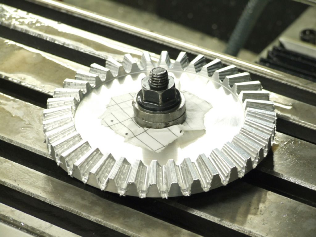 And the finished gears: 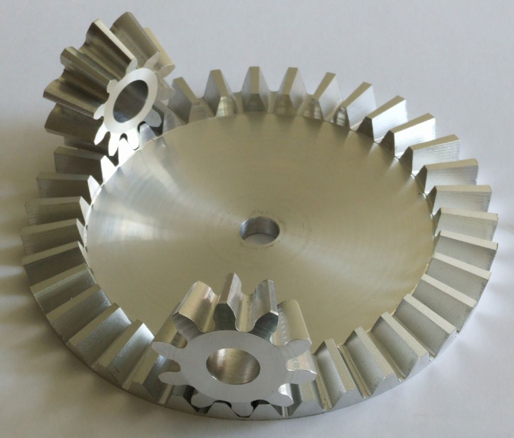 The gears mesh together extremely well; better than one might have thought looking at the finish. All I need to do now is make the real gears in cast iron. Regards, Andrew PS: If you think this is over-engineered, you ain't seen nuffink yet, wait till I get onto the steering gear. |
| Steve Withnell | 18/06/2011 19:45:36 |
858 forum posts 215 photos | Hi Andrew, how did you get rid of the machining marks on the crown wheel, that it was a graphic at first!
Since this is all done for pleasure and recreation, not sure why over-engineering is a problem
 Unless it causes it to be too heavy or too expensive of course. I'd have gone broke years ago if I needed to make a living off the models I make Unless it causes it to be too heavy or too expensive of course. I'd have gone broke years ago if I needed to make a living off the models I make Steve
|
Please login to post a reply.
Magazine Locator
Want the latest issue of Model Engineer or Model Engineers' Workshop? Use our magazine locator links to find your nearest stockist!
Sign up to our Newsletter
Sign up to our newsletter and get a free digital issue.
You can unsubscribe at anytime. View our privacy policy at www.mortons.co.uk/privacy
Latest Forum Posts
- *Oct 2023: FORUM MIGRATION TIMELINE*
05/10/2023 07:57:11 - Making ER11 collet chuck
05/10/2023 07:56:24 - What did you do today? 2023
05/10/2023 07:25:01 - Orrery
05/10/2023 06:00:41 - Wera hand-tools
05/10/2023 05:47:07 - New member
05/10/2023 04:40:11 - Problems with external pot on at1 vfd
05/10/2023 00:06:32 - Drain plug
04/10/2023 23:36:17 - digi phase converter for 10 machines.....
04/10/2023 23:13:48 - Winter Storage Of Locomotives
04/10/2023 21:02:11 - More Latest Posts...
- View All Topics
Support Our Partners


Shopping Partners
Subscription Offer

Latest "For Sale" Ads
- Reeves** - Rebuilt Royal Scot by Martin Evans
by John Broughton
£300.00 - BRITANNIA 5" GAUGE James Perrier
by Jon Seabright 1
£2,500.00 - Drill Grinder - for restoration
by Nigel Graham 2
£0.00 - WARCO WM18 MILLING MACHINE
by Alex Chudley
£1,200.00 - MYFORD SUPER 7 LATHE
by Alex Chudley
£2,000.00 - More "For Sale" Ads...
Latest "Wanted" Ads
- D1-3 backplate
by Michael Horley
Price Not Specified - fixed steady for a Colchester bantam mark1 800
by George Jervis
Price Not Specified - lbsc pansy
by JACK SIDEBOTHAM
Price Not Specified - Pratt Burnerd multifit chuck key.
by Tim Riome
Price Not Specified - BANDSAW BLADE WELDER
by HUGH
Price Not Specified - More "Wanted" Ads...
Get In Touch!
Do you want to contact the Model Engineer and Model Engineers' Workshop team?
You can contact us by phone, mail or email about the magazines including becoming a contributor, submitting reader's letters or making queries about articles. You can also get in touch about this website, advertising or other general issues.
Click THIS LINK for full contact details.
For subscription issues please see THIS LINK.
Digital Back Issues


Donate

 Register
 Log-in
Model Engineer Magazine
- Percival Marshall
- M.E. History
- LittleLEC
- M.E. Clock

ME Workshop
- An Adcock
- & Shipley
- Horizontal
- Mill

Subscribe Now
- Great savings
- Delivered to your door

Pre-order your copy!
- Delivered to your doorstep!
- Free UK delivery!
All Forum Topics > Workshop Techniques > A Challenge - How Would You Machine This Part?