Forum sponsored by:

Travelling Steady.
| Terryd | 13/03/2011 22:20:16 |
 1946 forum posts 179 photos | Hi Graham, I quite agree with your Golden rule of toolmaking, I also checked everything and anything when so employed. The British and European standards are quite exacting as Andrew points out the tolerances equate to h10. Oversize is not allowed in steel made to the standards. In Keith's example (6 - 18mmdia) the tolerance is +0 to -0.07mm, and as Andrew said out of round would be a max. of 0.035mm. From 18 - 30mm the tolerance is +0 to -0.085mm Obviously some will be out of round, some will be accurate depending on the wear in the die. I never said otherwise, I just cannot see how a helical form can be created in the process of drawing. In the process the material is held firmly in a fixed axis and any rotation is out of the question. Best regards Terry |
| Andrew Johnston | 13/03/2011 22:23:25 |
 7061 forum posts 719 photos | Posted by KMP on 13/03/2011 19:19:53: Hi Andrew, An ex MOD man, Hmmmmmmm  Oeeeeer, may be I should be economical with the truth on my CV! Keith; I've certainly seen nothing wrong with your sense of humour. There's no harm in disagreeing with people, and is indeed part of what makes such fora as this interesting. It is only when disagreements become personal that problems arise. Fortunately that seems pretty rare on this forum. Regards, Andrew |
| Andrew Johnston | 13/03/2011 22:27:38 |
7061 forum posts 719 photos | Hmmmmm, slowly but surely the memory is grinding into action out here in the sticks. I'm sure I have bought round stock with a helical pattern on it in the past. I have in mind that it was stainless steel of some variety. It's too late to ferret around in the workshop now. I'll have a look tomorrow evening to see if I can find some. Regards, Andrew |
| mgj | 13/03/2011 22:35:26 |
| 1017 forum posts 14 photos | Well use the blush icon then. Helical wave - I have some bar in the larger sizes - 1.5" or bigger that has a spiral pattern on it. I've never measured it to see if its acutally a change in dimension. SS -acceptable finish. I can get an acceptable finish using carbide tips, or HSS without too much rake, but it remains a dull grey and needs polishing to get really smooth. Using emery and oil I got my locos crankpins like mirrors. But inside a thread, no I couldn't get it smooth enough to be good in a bronze nut. . In industry I suspect a lot of these threads are finish ground, so we, lacking such kit, have to go a different route. Technically I could use the Quorn head as toolpost grinder -but no way is that kid of grit getting anywhere near my lathe. Having said that, Chaddock in his book on the Quorn shows it being used to grind all sorts of exotic spirals. There is a spiralling head where you mount a former on the back of the head, and effectively you copy grind, and on that basis all you have to do is dress the wheel to shape and set the right helix angle - which is no worse than grinding HSS to shape. Do a camshaft 6" long or so, as well as spirals. I've done helical endmill flutes very successfully as well, so you could thread grind up to 6-8" IIRC Chaddock used the system to grind the 2 cams on a model of the immortal, but ill fated BRM 1500cc supercharged racing engine. |
| mgj | 13/03/2011 22:39:02 |
| 1017 forum posts 14 photos | Terry - can the die not rotate in some processes. |
| KMP | 13/03/2011 23:41:39 |
| 73 forum posts 2 photos | Andrew,
Nothing to worry about I have some
in my own background that's all.  They tell me counselling would help but I keep telling them "I am not a number". They tell me counselling would help but I keep telling them "I am not a number". Good bottle of wine tonight
Keith |
| Nicholas Farr | 14/03/2011 00:36:16 |
 3988 forum posts 1799 photos | Hi all, I haven,t had any reason to measure out of roundness to any great extent in bright bar stock in places I've worked, but yes I've seen a spiral pattern along the length shown up by the layer of protection oil which is usually on them.
I don't know that much about the drawing process in the flesh as you might say but I've wondered like mgj suggests, if either the die is rotated or the bar itself is rotated while being drawn. This I think may help keep the bar as striaght as possible and even out any wear in the die maybe.
Regards Nick. |
| KMP | 14/03/2011 01:01:29 |
| 73 forum posts 2 photos | Graham, Terry, mgj
A final thought before retiring, drawing is not the final process in the manufacture of drawn bar. After and during drawing the bars are straightened firstly by a series of three roller stations and finally by a two roller station (convex and concave rollers). Perhaps the final two roller particularly could impart the helical patern?
Keith |
| mgj | 14/03/2011 11:07:33 |
| 1017 forum posts 14 photos | Sounds very reasoanble.
I don't know much/anything about drawing.
All my experience in the steel line was hot rolling ferritic armour, and casting steel armour. Plus forging. What you might call the heavy stuff.
|
| KWIL | 14/03/2011 11:41:48 |
| 3681 forum posts 70 photos | I have seen the same wave effect on Silver Steel bars, [which are ground to size]. If you have a reciprocating sleeve on such a bar the pattern shows up. |
| Terryd | 14/03/2011 17:06:55 |
1946 forum posts 179 photos | Graham, I never said that your sample did not have an helix, I just drew your attention to the fact that you described drawn material as rolled. If your sample is cold rolled it may well have a helix. I merely said that I couldn't see how drawn material has such a pattern and since than there have been more of the esoteric and outlandish ideas from a simple statement. The dies are fixed on a drawbench by the way and should not rotate, that can cause distortion and torsional stresses which would be disastrous to the strength of the steel. Cold drawn is straight due to the tension of the pulling process in much the same way that wire is straightened by a swift tug while one end is clamped. Silver steer is not left as drawn, it is centreless ground for dimensional and profile accuracy with the material passing a grinding wheel longitudinally which will explain the helix patterns seen. I wish folks would read what I write and not what they think I write. Best regards Terry |
| mgj | 18/03/2011 08:36:56 |
| 1017 forum posts 14 photos | I thought the whole idea of 2 fingers and a tool was to give the three ponts of contact and a triangle of forces with a resultant of zero. In other words there is no point is having an extra finger on a travelling steady - the tool povides the third finger and the force in the tool is counterbalanced equally and oppositely in the other 2 fingers. If you have an extra finger and it gets in the way of the tool, which it will, then you have to displace it which creates a twisting moment.
Lifewise a fixed steady - you still have 3 points of contact, (in almost all cases). One has a fixed finger because the steady is fixed (of course) so the tool is not in line ansd one still needs to generate that trianlge of forces.
Myford have not compromised - they have achieved perfection in suport as long as the width of the fingers in a TS spans the "width" of the leverage creating any turning moment (allows for the tool not being placed exactly centrally within the fingers) Won't always, but should do when say screwcutting.
|
| mgj | 18/03/2011 13:51:01 |
| 1017 forum posts 14 photos | Well I think the business of workpiece bending had already been covered to a degree, as had the benefits in some cases of cylindrical supports - more of course on very slender shafts which are rather more specialised than the normal travelling steadies are designed or suitable for.
As for your being right- yes I'm sure you are, - perhaps you had better let messrs Myford and Harrison know.
Luv Noddy. - struggling to find a proper understanding. Some manners too. Edited By mgj on 18/03/2011 13:55:23 |
| mgj | 18/03/2011 19:42:50 |
| 1017 forum posts 14 photos | I don't know Gray. If one is talking of finger wear, I've always adjusted the fingers. Line contact is theoretically best, but an arc is fine by both of us. Curved tips and rapid wear. Agreed, but I have usually just attacked the tips with a file - to "reface" them. but I stress I don't use them so much these days. I have never used them enough to have to replace the tips/blocks Heating - hopefully overstated because I let my coolant pump pour coolant over the fingers because mine are always that close to the tool . Also lubricates. I think it depends on the job - the bog standard steady is going to be fine 99% of the time, and thats what the pros design them for - general purpose "slender shafts" if there is such a thing, The problem I find is one of size when dealing with very slender shafts. Because then the shaft IS going to flex like hell, and the fingers are too big. So then I revert to this funny tool I got from Chronos, where you drill a hole in a blank held in the holder, and then move the cutter within this holder. (Having started the cut on a thicker bit of metal right up by the tailstock centre. Probalby telling my granny. -sorry - for a man making small engines. ) What I'm not so keen on is an externally fitted 4 point contact because then you lose the "self aligning/self diametering " part of the setup. I don't htink I have ever had chatter with a travelling steady - or if I have I have treated it as an indication that adjustment is out, because chatter is a small high frequency movement, and that as we all know is not possible with 3 points of contact. The implication being that one ain't got the contact that one thought! I suspect thats a more realistic appraisal of the situation. Back to heat. I do know that a lot of people cut dry or with brushed on coolant, to which one can only say that there are advantages in cleanliness, but you pays at other times, and tightly set steadies is one of the times one will pay. Take a choice? I have an Axminster cheapie pump, but a garden pond one is pretty good. Delivers through a 2mm dia vetinerary needle, and gives enough coolant to do a job, but doesn't splash badly. So perhaps thats one way round the problem of heat, wear (up to a point) and chip clearance. (Flow regulator is a little steam globe valve.) 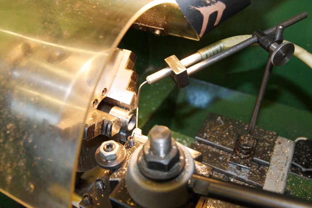 Edited By mgj on 18/03/2011 19:56:29 |
| mgj | 18/03/2011 22:31:12 |
| 1017 forum posts 14 photos | Yes - this lathe came with a loc line thingy, and so did the mill. I just couldn't get the end of the loc line to stay put, or point near the right place - and I got wet and lost my sanity. Hence the change! This does work well - it goes where you want it, in quantities from drop by drop to a good chip clearing jet. One of those success stories. The other cause for a smile is this eve, after a year of putting up with very nearly right, I got the TEs valve gear perfect.. Now she self starts as she should, will tickover at nil RPM (sort of), and you can just hear the feed pump clack box tickin. If it wants to be a bit feminine about starting, just fiddle the reversing lever, and the crank goes backwards, forwards and away as its meant to. Oh and its more powerful and uses less water.  So thats a success too - especially for one who don't know the front of steam engine from the back. Whats that to do with this post - nowt lad, Didn't even use a travelling steady in the manufacture! Edited By mgj on 18/03/2011 22:32:18 |
| chris stephens | 19/03/2011 00:44:33 |
| 1049 forum posts 1 photos | Hi MGJ,
Could that be a Tangential tool in your picture?
I have become even more of an "expert" on these tools, as I have got about 90% of the work done on a batch of 6 of the superior version. One of them has your name on it to replace the "loan/trial" one. Myford fit do you?
chriStephens
PS just to fit in with the travelling steady , I used one once, never found it necessary since.
No one has yet mentioned the travelling steady with two rollers and has the cutting tool as part of the arrangement ie the Roller Box. Seems to me that this is a superior way of doing things and removes the argument over where the TS's fingers should be.
|
| mgj | 19/03/2011 09:35:18 |
| 1017 forum posts 14 photos | No - its not A tangential tool. Its THE tangential tool. Still munchng metal. Myford fit is fine thank you kind sir. Cuts so well that even on the big chinaman it woun't be outclassed. Shift a lot of metal they do. (Tangential tooling is engraved on me 'eart nowadays, engraved on me 'eart it is) I'm not familiar with the box type of TS , but from what you are saying its very like the Chronos thing I'm on about - in principle, not necessarily in detail - where tool and fingers/support (wahtever sort) are integral to the set up. I'll bet it is very god. The problem I'm thinking is less one of support and more one of size and access. Machine a replacement for a milling machine leadscrew, and its a 1" dia thing. Pop a TS on it, somewhere close to the tool, chomp positively and you have to work quite hard to cock it up.Try and do the same thing on one of Grays tiny relatively long camshaft blanks and it all gets a bit more critical, and a different approach may well be called for. However, whats not to be deviated from is - 3 points of contact, obviously, and has been so for the better part of a thousand years, (unless there is a very specific reason not to) and get the forces in line in so far as is possible. Rules, as Dr Johnson famously said, are for the guidance of the wise, and the blind obedience of fools.  Edited By mgj on 19/03/2011 09:38:22 |
| mgj | 19/03/2011 11:45:10 |
| 1017 forum posts 14 photos | Tell you the other thing we haven't looked at Gray - thats longitudinal adjustment. Over squinge the tailstock and add heat and thats about as sure a way of introducing a swerve as one can get - particularly as no tailstock is ever "perfectly" aligned, so a moment will be introduced. Too slack and a bit of chatter creeps in? I have seen people, when chatter creeps in adjusting steadies, when possibly they should be adjusting tailstocks? Edited By mgj on 19/03/2011 11:47:36 |
Please login to post a reply.
Magazine Locator
Want the latest issue of Model Engineer or Model Engineers' Workshop? Use our magazine locator links to find your nearest stockist!
Sign up to our Newsletter
Sign up to our newsletter and get a free digital issue.
You can unsubscribe at anytime. View our privacy policy at www.mortons.co.uk/privacy
Latest Forum Posts
- hemingway ball turner
04/07/2025 14:40:26 - *Oct 2023: FORUM MIGRATION TIMELINE*
05/10/2023 07:57:11 - Making ER11 collet chuck
05/10/2023 07:56:24 - What did you do today? 2023
05/10/2023 07:25:01 - Orrery
05/10/2023 06:00:41 - Wera hand-tools
05/10/2023 05:47:07 - New member
05/10/2023 04:40:11 - Problems with external pot on at1 vfd
05/10/2023 00:06:32 - Drain plug
04/10/2023 23:36:17 - digi phase converter for 10 machines.....
04/10/2023 23:13:48 - More Latest Posts...
- View All Topics
Support Our Partners


Shopping Partners
Subscription Offer

Latest "For Sale" Ads
- Reeves** - Rebuilt Royal Scot by Martin Evans
by John Broughton
£300.00 - BRITANNIA 5" GAUGE James Perrier
by Jon Seabright 1
£2,500.00 - Drill Grinder - for restoration
by Nigel Graham 2
£0.00 - WARCO WM18 MILLING MACHINE
by Alex Chudley
£1,200.00 - MYFORD SUPER 7 LATHE
by Alex Chudley
£2,000.00 - More "For Sale" Ads...
Latest "Wanted" Ads
- D1-3 backplate
by Michael Horley
Price Not Specified - fixed steady for a Colchester bantam mark1 800
by George Jervis
Price Not Specified - lbsc pansy
by JACK SIDEBOTHAM
Price Not Specified - Pratt Burnerd multifit chuck key.
by Tim Riome
Price Not Specified - BANDSAW BLADE WELDER
by HUGH
Price Not Specified - More "Wanted" Ads...
Get In Touch!
Do you want to contact the Model Engineer and Model Engineers' Workshop team?
You can contact us by phone, mail or email about the magazines including becoming a contributor, submitting reader's letters or making queries about articles. You can also get in touch about this website, advertising or other general issues.
Click THIS LINK for full contact details.
For subscription issues please see THIS LINK.
Digital Back Issues


Donate

 Register
 Log-in
Model Engineer Magazine
- Percival Marshall
- M.E. History
- LittleLEC
- M.E. Clock

ME Workshop
- An Adcock
- & Shipley
- Horizontal
- Mill

Subscribe Now
- Great savings
- Delivered to your door

Pre-order your copy!
- Delivered to your doorstep!
- Free UK delivery!
All Forum Topics > Model Engineers' Workshop. > Travelling Steady.