Forum sponsored by:

New I/C diesel project - ETA15d-x2
| David Clark 1 | 07/06/2011 15:21:49 |
 3357 forum posts 112 photos 10 articles | Hi There
Let me know which issue and I will put it as the demo issue for a while.
regards David
|
| Ramon Wilson | 07/06/2011 22:42:26 |
 1655 forum posts 617 photos | Hi John, Not sure I like the thought of all that grinding grit and diamond dust around the lathe. I recently cut the wrist pins in the lathe using a small grinding cut off disc and despite covering the surrounding area with oily rags it still felt as if it managed to get everywhere. That said you obviously got a result which is what matters - are you able to expand the stone in the bore by any means?
My attempts at true honing have yet to begin. The Delapena I bought is yet to be set up as having decided I don't want the mess of honing fluid everywhere I need somewhere to put it - I have cleared an area for an extension but have spent what time I have of late on the engines.
I lapped these liners using a home made lap. I have made several of this type over the years and they work extemely well. I'm not sure where I got the idea from but I think it may be a Len Mason design. They're easy enough to make as long as the solder doesnt creep too far around the inside. I always coat both surfaces with soft pencil lead, leaving a strip for the solder, which seems to act as a barrier well enough.
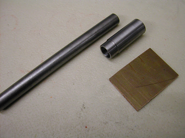   It is then silver soldered along its leading edge before turning to fit the bore.
 I use carborundum powders starting at 260 grit up to 1000 mixed with thin oil. Good care taken to the cleaning of parts and lap between each change of grit. Speed about 400 rpm
Pic above is 'after the event' all liners having been lapped at this point. The washer is to prevent the liner scuffing on the chuck.
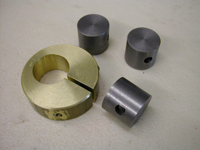 For pistons I have made this type of lap which as previously mentioned also works well. Both the pistons and liners had about .025 - .04mm left on for lapping
The long awaited final assembly is approaching fast - all that's left to do are the cylinder head bolts, the venturi system for the S&J version and finishing off the needle valve parts which were mostly made today. Not long now then
 I have no idea which MEW the Alan Booth 'Grindall' is in John but I do know someone who has every issue. If you can give me an idea of the period you think it was I'll see if I can find it
Hope the above on laps is useful to someone
Regards - Ramon
Edited By Ramon Wilson on 07/06/2011 22:45:15 |
| Ramon Wilson | 08/06/2011 22:32:40 |
1655 forum posts 617 photos | Hi again,
I've just received the following PM regarding the lapping post above. As there may be others feeling the same I thought it best to answer here rather than answer directly.
It read as copied .........
As ever, I'm following your posts with great interest. I'm afraid this may be a silly question, so I hope you won't mind me asking you direct rather than 'in public'. Of course a public answer might help someone else reluctant to ask in the first place! Finally, how ever did you turn a flat piece of 10 swg copper into such a beautiful cylinder? Firstly let me say that which many others have iterated on this Forum before - that is that no question is silly, stupid or otherwise if you don't know the answer. That's what makes this forum such an asset - a question answered, no matter how one feels it may be seen, may also answer it for others at a stroke so really, no one should be reluctant to ask.
So then ... the lap. The copper was annealed first before holding it in a vice against a piece of round bar the same size as the head of the lap 'mandrel'. The head diameter was turned such that the copper once soldered in place would allow sufficient for cleaning up to the size required. The copper was tapped around the steel re- annealing as required - if I recall correctly about three or four times. It needs to be a good fit on the head of the lap. The gap should be as close as will allow access for silver soldering. It can be improved by running a milling cutter through it holding it endwise in the vise of course.
The copper can be held in place on the mandrel head by a screw in the adjusting screw hole but make sure this screw is well carboned up as if this gets silversoldered in then its start again time. Once the soldering op is complete the cut off half is inserted into the lap and the adjusting screw set in so that it is just exerting pressure on the copper. Set in the lathe this is then turned using a very sharp tool. Please note however if the silver soldered edge is not the 'leading' one then you will very quickly unwind the copper
  The size to aim for is such that it will just enter freely the bore. If the bore is slightly tapered then it should just do so at the narrow end.
The lap is not charged by rolling in abrasive powder on a hard surface - rather the powder, mixed with light oil, is applied to lap and liner and the liner pushed over the lap. It should be a tight but not overly so fit. Start up the lathe -around 400 rpm - grasping the liner which should allow the lap to revolve with a reasonable drag - if it is difficult to hold against rotation or gets hot then stop, back off the adjusting screw and repeat. Parafin and light oil at about 10:1 makes an ideal lubricant. It gets messy so cover the lathe and wear gloves if you don't want black hands - really black on cast iron
 The lap is fully adjustable by increasing pressure on the inserted floating half of the head via the grub screw and whilst the expansion is not fully radial it does remain round and will true a slightly out of round bore. If the liner is tapered to begin with the taper can be taken out by dwelling in the tight area more but we are talking tapers of tenths here not thous. Conversely putting in a desired taper is done the same but 'opposite' way. Providing the adjusting screw location is on the centreline of the length of the copper the lap expands parallel.
 This is the lap after the initial lapping of all three cylinders using 260 grit. It is important to thoroughly clean lap and part before going to the next grit. If the surface finish from the tool is good then you should be able to begin with 400-600 grit. I began as such but had left too much on so reverted to the 260 to remove the initial amount quickly.
Something I did overlook to mention before was that these laps are not 'specific' in that within the amount of copper left they can Edited By Ramon Wilson on 08/06/2011 23:01:33 |
| Ramon Wilson | 08/06/2011 22:33:39 |
1655 forum posts 617 photos | Something I did overlook to mention before was that these laps are not 'specific' in that within the amount of copper left they can be further turned to suit smaller bores.
Well XXXX ('name withheld to protect the innocent'
 ) I hope that helps to answer your questions and of course anyone else I may have confused. I would just like to emphasise this is very definitely not the way to go about it, merely the way I have tackled it --- and they've got to run yet! ) I hope that helps to answer your questions and of course anyone else I may have confused. I would just like to emphasise this is very definitely not the way to go about it, merely the way I have tackled it --- and they've got to run yet!As always hope that's useful
Regards - Ramon
Edited By Ramon Wilson on 08/06/2011 22:34:42 |
| David Clark 1 | 09/06/2011 04:35:43 |
3357 forum posts 112 photos 10 articles | Hi Ramon
How about an article on making the laps.
For Model Engineer.
regards David |
| Ramon Wilson | 09/06/2011 08:12:42 |
1655 forum posts 617 photos | Hi David,
PM sent
Regards - Ramon |
| Bill Starling | 09/06/2011 10:10:26 |
| 102 forum posts 7 photos | As the 'protected innocent' mentioned by Ramon, I feel suitably chastised for not coming straight out and asking my question openly. So – publicly – thanks for a superbly detailed and helpful answer. It has been 'cut and pasted' into my 'Tips from the ME forum' file, which is growing steadily. |
| jomac | 09/06/2011 13:36:49 |
| 113 forum posts | Ramon Hi. Thats a great idea for an internal hone/lap, I sometimes start to lap with valve grinding paste, just to get the lathe tool marks out, (over exuberance and no patience) I have got 12 tubes of diamond paste, they cost about A$9, so they are much cheaper now than years ago, then finish with Brasso. The internal hone that I tried with SS rod and a fine stone, I should have said that the length of the actual stone is about 35mm long, that way there is less chance of distortion, as it wears more evenly, I have got two slate oil stones which are at least a 100 years old, so I aint cutting those up, so I might get a slate tile and see how that goes. over in the UK just wait for a wind storm you should have plenty???? I think in a previous post. that I do what Dave Owens does and use a thread die holder, to hold a slotted and grooved piece of round Aluminium, that makes it adjustable. Anyway a Gindall or a Delapina is a better option, especialy the one by Tom Blough.. I have a small roll of cling wrap that I got from the butcher/greencrocer, its wider and a bit thicker than domestic stuff, CHEAP if you ask the butcher nicely ie FREE. Providing you dont have to traverse the saddle very far, it some times sticks to the lathe bed, and also wrap it clock around the chuck, it keeps most of the rubbish out of the moving parts, the grit also sticks to it. PLEASE be careful with things spinning on a revolving part. then just screw it up when you have finished, and give the lathe a wipe with an oily rag. works for me!!!! Now, the Allen Booths article on the external hone that was mentioned by Dave Fenner, in his article on the Sugden Special. At the present this time I cannot get to my MEW mags, but I think its somewhere in the 90s (I am also having trouble getting the on line index to work as well) maybe someone out there has a better memory than me, can help. I apologise for my spelling and grammer, as I can only type with two fingers and have to look at the keyboard to do that!!!!, just hope it makes sense???? John Holloway |
| Ramon Wilson | 09/06/2011 23:33:31 |
1655 forum posts 617 photos | No need to apologise John it all makes perfect sense. I can't type without looking at the keyboard either which makes for some interesting typos I can tell you
I have diamond paste too but if it is used on 'soft' materials it can inbed itself in to the surface of the metal despite being well cleaned. I guess that would make for some interesting lapping when the engine first fires up. My understanding of it is that you really need an ultrasonic cleaner in order to clean the parts before assembly.
So far I have only used carborundum and on occasion finished off with crocus powder. Recently I was given a very small drop of 'Diamantine' a white powder which gives a super high finish but which apparently does not imbed itself but I have as yet to use it.
I've had a reasonable couple of days making the needle valve assemblies and this has incurred a couple of small techniques which some may find useful.
The needles are made from 16swg piano wire. The initial point is ground by hand on the off hand grinder holding it at a shallow angle to the side of the wheel. It's then held in the lathe and the very tip supported by a piece of hard wood set such that the top surface is just above the centreline. The wood is brought up to the needle so that it penetrates 2-3mm and then using a smooth file the wood is filed through and the taper smoothed and brought true. This works surprisingly well - it's also a good way of supporting a slender shaft if theres need to reduce it slightly by filing.
 The piano wire is a couple of thou larger than the nearest drill size so a piece was cut off and tapered, again by hand on the off hand grinder to a very shallow angle on one side only. (It's neccessary to keep this cool and not lose the temper by overheating)The burss are smoothed away with a small oilstone then this is held in the drill chuck and used as a reamer. It works extremely well but it is important to constantly remove it to clear the swarf. If this is not done it will quickly build up and backup in the taper to wedge itself well and truly - please, don't ask
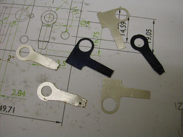
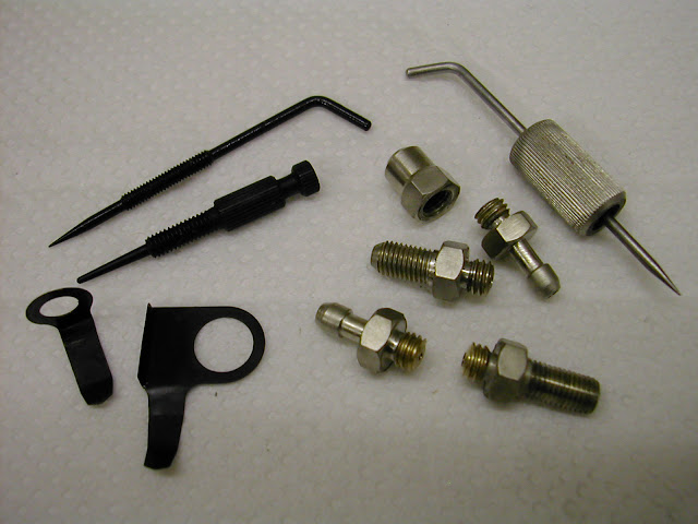
  These are for the Mks 1 and 2. The S&J version is from ali and steel and is as yet to be made.The screw thread on the lower needle is 7BA studding drilled and reamed as above and Loctited on. These are the parts that are intended for nickel plating The last items are the spring ratchets for the MK2 and the S&J and these were made by clamping a piece of .2mm planished spring steel and some springy phosy bronze strip between two pieces of mild steel. Despite the tight bolting, the cutting forces - particularly noticeable as the two thin layers of bronze work hardened despite a sharp cutter - still forced burrs between the layers of the shims.
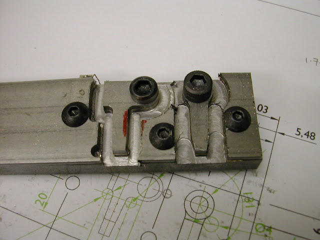  Fortunately only one of each is required
The phosy bronze is actually silver plated hence the colour - does any one know how to turn it black ?
As usual - hope this of interest to someone
Off to my old works tomorrow to get some steel for the cylinder bolts - next week should see the final parts bite the dust then.
Regards Ramon |
| Ramon Wilson | 18/06/2011 21:19:07 |
1655 forum posts 617 photos | I really don't like digital calipers!
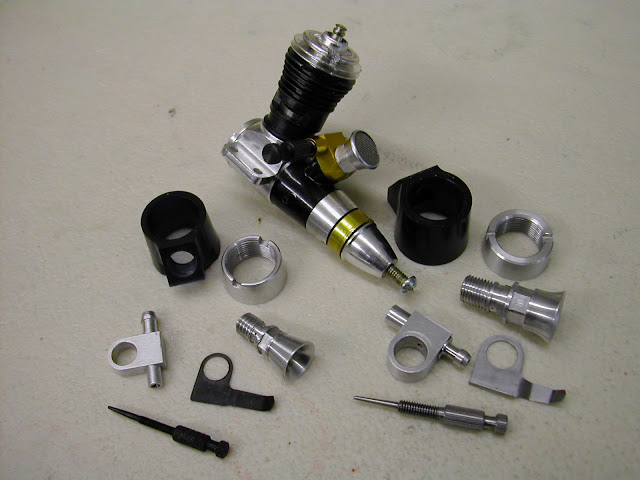
Actually I never have done but these were a gift and, it has to be said, they are so much easier on the eyes than conventional ones it's easy to succomb. Well...... I really don't like them now ...... All the parts are now machined for all three engines - well I thought they were until today.
 This is the sum total of the parts ready for assembly and they have now all gone together well with very little fettling required - just a small scraping inside the crankcases to allow the big ends to clear where the bore enters the case and a small amount of clearance milled on the S&J backplate to clear the piston at BDC (the S&J backplate has a much deeper register) When I measured the 'Cox' carb body and venturi I did so while my friend who'd brought it over waited. I used digi calipers and made a note of all dimensions. The sketches done the engine went off and the parts were drawn out to the dimensions. Once assembled on the S&J however it looked a little out of scale so I asked for another loan. First thing noticed today then was that my version was somewhat thinner than the original
I'd kept the original sketch and dimensions so it did not take long for the penny to drop. Some dimensions were correct but others a consistent 1.38 short. I guess I must have inadvertantly re-zeroed it whilst measuring
- something easily done with the pair I have. Deary deary me I said or something rather similarApart from this small set back - the parts will require making again - I have had an attempt or two at nickel plating the needle valve parts. Though not totally satisfied with them so far they do actually look better 'in the flesh' than in the image and far more in keeping than just plain brass. All three parts were made from the same piece of brass but all three exhibited differing qualities of finish. Strangely enough the reduced diameter of the fuel inlet plated with a shiny, bright, almost chrome like finish but the rest was more a dull grey. More work is need here really to get something more satisfactory and consistent but the amount of plating salts is limited for too much experimentation. Whatever this is what the first off looks like after the test assembly - it has to be stripped for anodising so has not been run yet.
 I'm off to Duxford for a day out tomorrow but next week should see them finished and running - more a bit later then.
Regards for now - Ramon |
| Ramon Wilson | 24/06/2011 22:36:28 |
1655 forum posts 617 photos | Hi again.
Well further to the last post I'm glad to say things are now back to square one
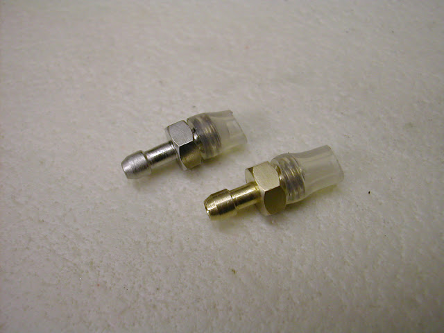
New parts have been made and they are much more in scale and in keeping to the original.
 This shows before (on the left) and after (right) and the engine from which the parts were copied.
The other accomplishment has been the nickel plating. I was not happy with the previous parts so re-cut all the hex surfaces and began again. I also cut several more small test pieces from the same bar. Starting with these at perhaps a somewhat more observant pace I found the initial flash of plating was quite shiny and formed rapidly - a matter of seconds in fact. I had also misled myself by thinking that the plating action should give off a rapid fizzing and began with a current which created such but it quickly became obvious that this was detrimental to the finish. By reducing the current right down until the fizzing was barely perceptible the finish showed a dramatic improvement.
By the time I felt ready to try the parts again I was down to very low current and literally dipping the part in and out of the solution for no more than a couple of seconds.
It still proved slightly inconsistent part to part but the results are far better than the first attempt and give an acceptable overall look installed on the engines. The solution used was bought off ebay - a litre for 9.99 plus postage. There is sufficient nickel in the solution for a small amount of plating without the need for a nickel anode. It appears to have worked well on this basis in this situation so its fair to say I'm well pleased with the outcome - albeit not perfect it proved much simpler than anticipated.
 This was the first part done - the silicone tube is to prevent the threads from plating - lesson learnt the first time as they became very tight in the intake!
Degreasing is obviously an important factor too. The parts were cleaned in acetone first then washed in water. A 2-3 min dip in 10;1 sulphuric acid followed by another wash then a final 5 min soak in distilled vinegar and salt solution as recommended. Despite this I feel the parts were still not clean enough in areas. On the larger knurled needle valve the area which must have had some flux residue from soft soldering the needle in
simply would not plate at first until it had really been abraded using a small piece of Garryflex abrasive block. Even now there is a change of colour that whilst acceptable can still be seen.
 All the parts finished including the 'backadised' parts. This was done using Koldblak - nothing very special to that - it's very easy to do but what is surprising is that the Koldblack was bought in from my works in 1985 and this was done in the small tub of solution mixed originally all that time ago. Some shelf life eh
It's so long ago I have forgotten the ration of neat Koldblak to water - 5 to 1 seems to ring a bell - does anyone know the correct ratio?Well if all goes well the anodising should be done next week then it's time for a run up
As usual - hope this is still of interest
Regards - Ramon
|
| Mike | 26/06/2011 10:43:00 |
 713 forum posts 6 photos | Hi Ramon,
I hope you don't mind your excellent and informative thread being disrupted by an old codger's reminiscences, but it has brought back to me memories of a time in the 70s when a pal and I ran a pair of ETA Elites in control line team race events. Like you on one of your engines, we made Cox-type carbs (in the local tech school workshops) - couldn't see the point in reducing the flow through the venturi with the spray bar. As I recall it was quite successful once we hit on the right diameter and tapers, although we never did get as far as copying the Cox drum valve.
Another thing we did was to fit aluminium bronze contra pistons, with the thought they would aid heat dissipation. The al-bronze was valve guide material scrounged from the old BRM Formula 1 workshops at Bourne, Lincs. - a fascinating place to visit.
I can also remember seemingly endless fuel brewing experiments to get 34 laps at max power out of the allowed 7cc of fuel. Best anaesthetic-grade ether rather than solvent, and I also remember writing to all the leading paraffin manufacturers to ask them the calorific value of their fuel. I think the engines ran best on Aladdin Pink! We also tried many different oils in addition to the usual Castrol R, and I seem to remember a lubricant developed by Valvoline for outboard hydroplane racing allowed us to considerably reduce the oil content of our fuel.
We were the champions of our own club for a couple of years, but never got further than the quarter-finals in the Nationals.
Ramon, many thanks. You have brought back some very happy memories! |
| Ramon Wilson | 26/06/2011 23:50:22 |
1655 forum posts 617 photos | Hi Mike, No I don't mind at all, in fact it would be pleasing to hear a few more
Although a life long control line flyer I only had a short foray into team racing in the early/mid nineties via trying to encourage some youngsters to get involved with 'Mini Goodyear'. That died an early death due to lack of interest after the initial buzz - that's the kids lack of interest, not us.
My interest in TR though was from the outset but for some reason this corner of Suffolk never seemed to produce any like minded competively interested parties so it remained for years very much a 'magazine led' interest.
Mini Goodyear did however take a hold and my wife became my pilot for about three years. We never did particularly well mainly due to not having powerful enough motors - at the time all plain bearing - and never anything that would consistently re- start 'first flick' but we did enjoy ourselves tremendously. It was this event that began my interest in trying to improve the performance of the stock engines - mainly MVVS 1.5's and PAW's which although never really successful did lead to making various bits and pieces - a forerunner of current interest. Ipswich 'boys' Green and Long' had something truly unbeatable but we never ever came close.
I also built a (my third over the years) Contest Kits Voodoo for an Oliver Tigre for vintage TR but this one proved a poor model in flight - undulating and difficult to keep in a groove. This period coincided with a deep (and my main) interest in C/L aerobatics along with some extreme pressures at work so I took a complete break for a year or so returning later to concentrate solely on the latter. I sold all my TR stuff off at the Nats swapmeet about eight or nine years ago.
Fortunately (?) there is little control line flown in this area now which I have to admit would be a big distraction if it were. It would not take much to respond to an ever present itch
Nice to hear your reminiscences on fuels, as you can imagine we dabbled a bit with that
too but the Ali- bronze CP is new. You'd have a job getting Aladin Pink these days though!
Thanks for your thoughts
Regards - Ramon
Edited By Ramon Wilson on 26/06/2011 23:52:36 |
| Ramon Wilson | 27/06/2011 23:36:03 |
1655 forum posts 617 photos | Well Guy's journeys end fast approaches......
I've had a really good session in the workshop today anodising all the requisite parts and the engines are now finally complete. There remains but one thing and that is to run them. I was about to do this this afternoon as the last part was done but my neighbour decided to have a Bar-B so I felt it was not exacly an opportune moment
- ''Maybe tomorrow Jack''The anodising itself went well but the dyeing could have been a little better. I used 'Waterman' ink - 'South Sea Blue' - for the blue which took well - too well actually it had to be diluted considerably to get the light blue I was after and even then it's a little brighter than I would have liked. When sealing it over boiling water I left it static and some of the colour leached out on the side nearest the water. Ready for this on the Mk 2 with a deeper blue I continually turned this which proved much better. However so keen to see what it would look like on the engine I sprayed WD40 over it too quickly and this leached out some colour too. The test pieces I had done were not sealed but left on the bench. I tried these to see if the WD would affect them but it was fine - lesson learnt there then - after sealing I shall let it stand for a good while.
So finally after this very pleasurable journey here they are
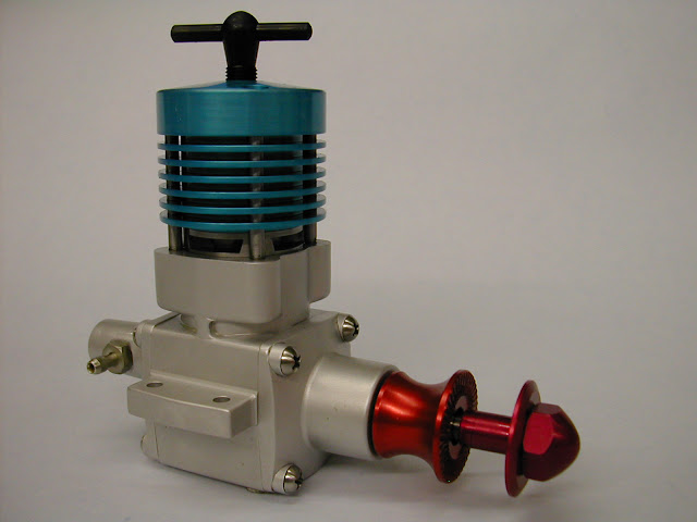 This is the Mk1. The colours are as the original the blue a little brighter perhaps but it did vary from engine to engine
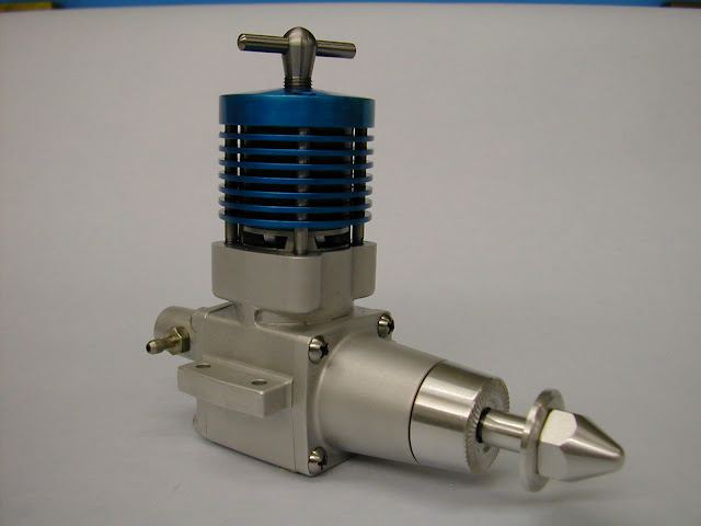 The Mk 2 had a sturdier and longer front housing along with a beefed up crankshaft. It also had an extra fin cut in the head. The prop drivers were not anodised but the compression screws were blacked. I decided not to on this one.
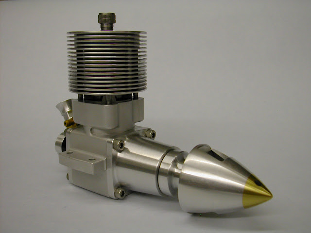 This is the Stocton and Jehlik version. Herb Stockton and Don Jehlik were an American team race pair that were very successful with their 'version' of the Eta 15. Apparently the only Eta parts were the liner and piston, crankcase and shaft. The August 1967 Aeromodeller featured drawings for the modified parts and these are what were used to recreate this as a 5cc. The original rotor disc intake was replaced by a steel drum running in an ali housing driven (as per a rotor) by the crankpin. As previously mentioned it utilised the front housing and venturi system from a Cox 049 glow engine.
Nothing matched the scaled up version so the housing was machined from hard plastic. The 'gold' anodising is just yellow dye.
 You know, it's strange but now they've been anodised I think I preferred them in 'all ali'. Well that's it folks - I'll let you know how they run tomorrow.
Regards for now - Ramon
Edited By Ramon Wilson on 27/06/2011 23:38:33 |
| Bill Pudney | 28/06/2011 01:41:11 |
| 622 forum posts 24 photos | Beautiful Ramon, just beautiful. Can't wait to hear how they run. I've thoroughly enjoyed your story, and the Racer one before it. Once again beautiful work!! best regards Bill Pudney |
| ady | 28/06/2011 07:45:04 |
| 612 forum posts 50 photos | Amazing to watch, and fascinating. Thanks for sharing. |
| Ramon Wilson | 28/06/2011 14:15:34 |
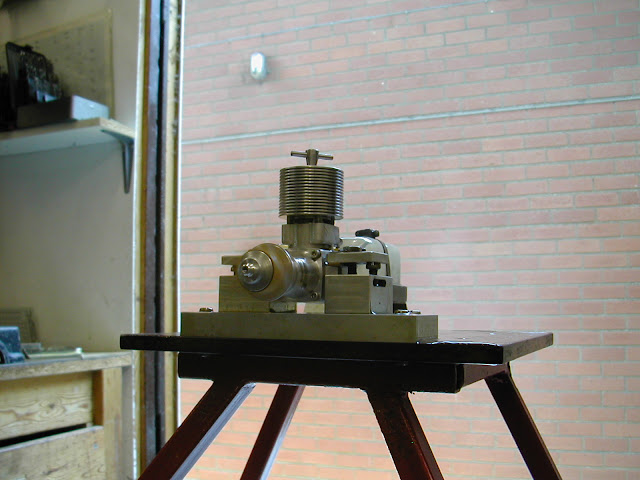
1655 forum posts 617 photos | Well that's it then folks, journeys end
 Mk 1
Set each one up this morning and pleased to tell they all started well once the compression setting was established and all appear quite powerful. They swung a 12 x 5 wooden prop with ease. No rpm check was done as obviously they need to bed in first and I had to think of the neighbours. They certainly have a lovely 'bark' and to hear and see them run after the build period is a real bonus.
 They were purposefully kept rich for this first run hence all the exhaust and whilst they were not run for long there was no evidence of excessive black exhaust gunge. Compression seals with the CI piston and En1a liners are better than anticipated - remains to be seen how long that will last though these engines will never have more than the occasional run.
 S&J Version
Just remains to say thanks for your kind words, Bill and Ady, and thank those who have responded over these last few months either by post or PM. It's been difficult to assess whether it's what is wanted by the majority but as you obviously keep looking I could only assume it was. Hope I haven't gone on too much
Now, I'm respectfully(?) reminded by my tolerant and ever patient better half that perhaps it's time to catch up on those domestic issues that have been somewhat neglected over recent weeks so it's time for a break for a short while before tackling the next one.
Regards to you all - Ramon Edited By Ramon Wilson on 28/06/2011 14:17:05 |
| Mike | 28/06/2011 15:22:29 |
713 forum posts 6 photos | Only one way to describe the whole project, and the way it was narrated - absolutely brilliant!
Incidentally, just finished reading Matt Oxley's book "Stealing Speed" - a must for anyone interested in two-stroke design and tuning. Highly recommended. |
| Bill Starling | 28/06/2011 15:37:08 |
| 102 forum posts 7 photos | Dear Ramon,
If any one had asked whether I was interested in small I/C engines I would have said 'No'. However I've been fascinated by your series. Superb workmanship, excellently described and illustrated. It's been an eye opener. Thanks very much. I'm looking forward to the next one.
Best wishes,
Bill.
|
| Windy | 28/06/2011 19:43:49 |
 910 forum posts 197 photos | Thanks Ramon a very informative series.
As an old ex motorcycle competition rider I have just ordered Matt Oxley's book "Stealing Speed.
I would like to see some articles on building and tuning model home built engines for maximum performance.
Any offers.
Windy |
Please login to post a reply.
Magazine Locator
Want the latest issue of Model Engineer or Model Engineers' Workshop? Use our magazine locator links to find your nearest stockist!
Sign up to our Newsletter
Sign up to our newsletter and get a free digital issue.
You can unsubscribe at anytime. View our privacy policy at www.mortons.co.uk/privacy
Latest Forum Posts
- *Oct 2023: FORUM MIGRATION TIMELINE*
05/10/2023 07:57:11 - Making ER11 collet chuck
05/10/2023 07:56:24 - What did you do today? 2023
05/10/2023 07:25:01 - Orrery
05/10/2023 06:00:41 - Wera hand-tools
05/10/2023 05:47:07 - New member
05/10/2023 04:40:11 - Problems with external pot on at1 vfd
05/10/2023 00:06:32 - Drain plug
04/10/2023 23:36:17 - digi phase converter for 10 machines.....
04/10/2023 23:13:48 - Winter Storage Of Locomotives
04/10/2023 21:02:11 - More Latest Posts...
- View All Topics
Support Our Partners


Shopping Partners
Subscription Offer

Latest "For Sale" Ads
- Reeves** - Rebuilt Royal Scot by Martin Evans
by John Broughton
£300.00 - BRITANNIA 5" GAUGE James Perrier
by Jon Seabright 1
£2,500.00 - Drill Grinder - for restoration
by Nigel Graham 2
£0.00 - WARCO WM18 MILLING MACHINE
by Alex Chudley
£1,200.00 - MYFORD SUPER 7 LATHE
by Alex Chudley
£2,000.00 - More "For Sale" Ads...
Latest "Wanted" Ads
- D1-3 backplate
by Michael Horley
Price Not Specified - fixed steady for a Colchester bantam mark1 800
by George Jervis
Price Not Specified - lbsc pansy
by JACK SIDEBOTHAM
Price Not Specified - Pratt Burnerd multifit chuck key.
by Tim Riome
Price Not Specified - BANDSAW BLADE WELDER
by HUGH
Price Not Specified - More "Wanted" Ads...
Get In Touch!
Do you want to contact the Model Engineer and Model Engineers' Workshop team?
You can contact us by phone, mail or email about the magazines including becoming a contributor, submitting reader's letters or making queries about articles. You can also get in touch about this website, advertising or other general issues.
Click THIS LINK for full contact details.
For subscription issues please see THIS LINK.
Digital Back Issues


Donate

 Register
 Log-in
Model Engineer Magazine
- Percival Marshall
- M.E. History
- LittleLEC
- M.E. Clock

ME Workshop
- An Adcock
- & Shipley
- Horizontal
- Mill

Subscribe Now
- Great savings
- Delivered to your door

Pre-order your copy!
- Delivered to your doorstep!
- Free UK delivery!
All Forum Topics > I/C Engines > New I/C diesel project - ETA15d-x2