Forum sponsored by:

Disassembling of Minimill / X2-clone / XJ-12 Ballbearings
Stripping down Chinamill
| Peter G. Shaw | 05/07/2010 13:20:11 |
 1531 forum posts 44 photos | Hi Marcus, Firstly, sorry about the words I used. I was probably trying to be very precise in what I was saying assuming good English. Second, your drawing is the same as mine, and therefore wrong as my machine is not quite the same. I will now go and take some photos etc. I'll report back later. Regards, Peter ps. I sent you an email via "My messages". Did you get it? |
| Peter G. Shaw | 05/07/2010 13:55:35 |
1531 forum posts 44 photos | Three photos which I hope will make it easier to understand what I did. Here goes..... 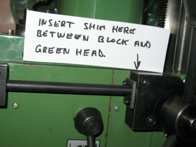 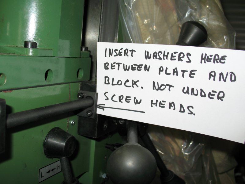 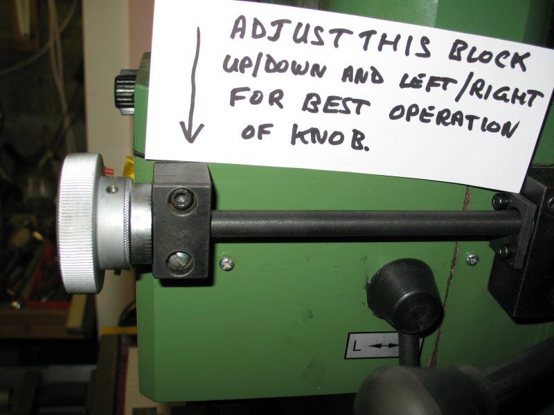 Does this help? If not ask again. In the top photo, I used a piece of shim steel about 15mm wide and the full depth of the black block. It has one hole through which the top screw fits. The shim then just hangs there until clamped by both screws. Th idea is to twist the block round vertically so that the horizontal shaft moves away from the milling head itself. In the second photo, the two washers are placed between the cover plate and the block and over the screws. It can be fiddly as they are small, and drop off easily. The idea is to lift the cover plate away from the block thus allowing the worm inside freedom to rotate. In the bottom photo, the idea is to move the block around until the shaft can rotate without binding, and the knob can rotate without binding against the block. It could even be that turning the black block round through 180 degrees sideways could help. It all depends on the location of the various holes. Mine are very poorly drilled, and I have plans to replace it sometime. Regards, Peter G. Shaw Edited By Peter G. Shaw on 05/07/2010 14:04:31 |
| MarcuSweden | 05/07/2010 21:22:42 |
 29 forum posts 20 photos | Thankyou wery much ! This did help ! Now i understand what to do and also why. I´m now ready with my conversion from gearwheel to belt, I will post some photos as soon as im done with some cleaning around the machines. Today i tried the minimill for the first time, and it was actually better than i thought, milled some steel with a 12mm endmill and also some aluminium with a 16mm endmill, it was really fun ! I have also bought one low price tachometer that i used today for checking the spindlespeed, i bought it from : http://www.dealextreme.com/details.dx/sku.18239 The price of the tachometer is very low and the quality is more than good enough for measuring millingmachines and lathe, free shipping also. The parcel came after 2 weeks and it works wery well. Right now i found the mail in "My Messages" , I will start looking at the messages more frequently! I will answer with message ! |
| Clive Farrar | 06/08/2010 22:57:27 |
 125 forum posts 41 photos | Well chaps my belt drive conversion is now finished.
To suit my machine I had to make several small dimensional modifications to the drawings I was working from. Mainly because my motor is totally different to that drawn.
Once I had sorted out the excessive bearing pre load that meant top speed was about 60 rpm it is running great.
It is much quieter than the gear drive.
Hi low top speeds have gone from 1100 to 1700 , 2500 to 3200 a good range and a good increase. Although for me I susspect it will rarely be out of low gear.
Very very pleased with the result and I would recommend the job to anyone who smashes their gears.
regards Clive |
| Ian S C | 07/08/2010 02:17:37 |
 7468 forum posts 230 photos | Hi Clive, what is the minimum speed the mill will run at? I find that the important speed, perhaps I try to do jobs that are too big, my mill is a bigger one, with a minimum speed of 90 rpm, I would like it to be 60rpm or less.Ian S C |
| Clive Farrar | 07/08/2010 20:50:38 |
125 forum posts 41 photos | Ian I can not say for sure as the only rev counter i have is for model aircraft and works in steps of 100.
It flickers on 1 but the tippex marks are going round too quick to count so I think it is fairly close to 100. It does not take much of an increase on the speed pot for it to steady at 1.
I have not tried cutting anything at that speed but I suspect it will only do very fine cuts when going that slow.
Mind you the pullys were easy enough to turn up so a slightly bigger one, 90 mm ?, would probably get you down to the speed you need.
Regards Clive |
Please login to post a reply.
Magazine Locator
Want the latest issue of Model Engineer or Model Engineers' Workshop? Use our magazine locator links to find your nearest stockist!
Sign up to our Newsletter
Sign up to our newsletter and get a free digital issue.
You can unsubscribe at anytime. View our privacy policy at www.mortons.co.uk/privacy
Latest Forum Posts
- hemingway ball turner
04/07/2025 14:40:26 - *Oct 2023: FORUM MIGRATION TIMELINE*
05/10/2023 07:57:11 - Making ER11 collet chuck
05/10/2023 07:56:24 - What did you do today? 2023
05/10/2023 07:25:01 - Orrery
05/10/2023 06:00:41 - Wera hand-tools
05/10/2023 05:47:07 - New member
05/10/2023 04:40:11 - Problems with external pot on at1 vfd
05/10/2023 00:06:32 - Drain plug
04/10/2023 23:36:17 - digi phase converter for 10 machines.....
04/10/2023 23:13:48 - More Latest Posts...
- View All Topics
Support Our Partners


Shopping Partners
Subscription Offer

Latest "For Sale" Ads
- Reeves** - Rebuilt Royal Scot by Martin Evans
by John Broughton
£300.00 - BRITANNIA 5" GAUGE James Perrier
by Jon Seabright 1
£2,500.00 - Drill Grinder - for restoration
by Nigel Graham 2
£0.00 - WARCO WM18 MILLING MACHINE
by Alex Chudley
£1,200.00 - MYFORD SUPER 7 LATHE
by Alex Chudley
£2,000.00 - More "For Sale" Ads...
Latest "Wanted" Ads
- D1-3 backplate
by Michael Horley
Price Not Specified - fixed steady for a Colchester bantam mark1 800
by George Jervis
Price Not Specified - lbsc pansy
by JACK SIDEBOTHAM
Price Not Specified - Pratt Burnerd multifit chuck key.
by Tim Riome
Price Not Specified - BANDSAW BLADE WELDER
by HUGH
Price Not Specified - More "Wanted" Ads...
Get In Touch!
Do you want to contact the Model Engineer and Model Engineers' Workshop team?
You can contact us by phone, mail or email about the magazines including becoming a contributor, submitting reader's letters or making queries about articles. You can also get in touch about this website, advertising or other general issues.
Click THIS LINK for full contact details.
For subscription issues please see THIS LINK.
Digital Back Issues


Donate

 Register
 Log-in
Model Engineer Magazine
- Percival Marshall
- M.E. History
- LittleLEC
- M.E. Clock

ME Workshop
- An Adcock
- & Shipley
- Horizontal
- Mill

Subscribe Now
- Great savings
- Delivered to your door

Pre-order your copy!
- Delivered to your doorstep!
- Free UK delivery!
All Forum Topics > Workshop Tools and Tooling > Disassembling of Minimill / X2-clone / XJ-12 Ballbearings