Forum sponsored by:

Ignition coils for small engines
| Martin W | 15/09/2010 14:57:03 |
| 940 forum posts 30 photos | Hi
Just been searching re high pressure v voltage breakdown and found this pdf file with data regarding pressure v voltage breakdown. It looks like a presentation document and page 16 gives a graph for breakdown voltages from low pressure to about 1000 bar; it also gives the low breakdown voltages for a variety of gases. Page 15 refers to the calculations and considerations re the breakdown processes.
I assume the data is valid as it has been produced at/for CERN
 , usual disclaimers etc. , usual disclaimers etc.Cheers
Martin |
| Howard Jones | 15/09/2010 18:16:20 |
| 70 forum posts 112 photos | guys in australia building model engines often use the Bosch GT40RT coil. it is quite small compared to the canister type coils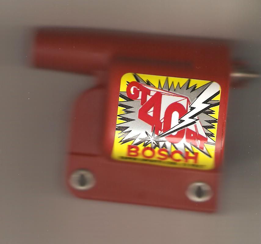 this was just placed on top of my scanner a moment ago to show you. those silver eyelets are 5cm centre to centre. the coil is designed for kettering type points. it is epoxy filled. they are about $59 Supercheap auto in australia. |
| Andrew Johnston | 15/09/2010 20:22:27 |
 7061 forum posts 719 photos | Hi Martin, Thanks very much for the link. The breakdown properties of air are much clearer to me now. I'm also an official idiot for not seeing what was in front of me! I didn't spot that the X-axis of the graph is a product, pressure times distance. So, let's say we have a spark gap of 0.5mm. According to the Paschen curve that equates to a breakdown voltage of about 2.5kV at one bar (close to normal atmospheric pressure). Without bothering to measure it I assume that my hit 'n' miss engine has a relatively low compression ratio, let's say 6. If we start with air at 1bar and 20°C and assume that the compression process is isentropic, and take the heat capacity ratio of air as 1.4, then according to my calculations we end up with air at 12.29 bar and 324°C at top dead centre. If we now go back to the Paschen curve we come up with a breakdown voltage of 25kV for a spark gap of 0.5mm and a pressure of 12.29bar. According to my Bosch Automotive Handbook spark voltages are normally about 25-30kV. At least this is in the right ballpark. The question is though, do our ignition systems really generate 25kV? And if they don't, how come they work? ETW talks about ignition voltages for model engines ranging from 2kV to 8kV. I suppose that what it all boils down to is that at some point one has to stop fiddling around with the maths and go and build something to see if it works! Regards, Andrew |
| Hugh Gilhespie | 15/09/2010 20:54:10 |
| 130 forum posts 45 photos | Andrew,
I suspect that the answer is in the air temperature. I would guess that the breakdown voltage falls off with increasing temperature, so perhaps 2 to 8 kV is enough? |
| Billy Mills | 15/09/2010 22:05:20 |
| 377 forum posts | The Paschen curves are not really applicable to a spark plug because of the geometry of the gap, they are for large parallel and smooth plates in Dry gas. Dielectrics ( fuel-air mix in this case) break down in a complex way. For example UV will cause the gap to fire at a much lower potential as will ionising radiation ( eg geiger tube) or carbon particles from previous cycles. Water vapor will also lower the breakdown voltage as will any combustion products. For a spark plug the electrodes have relativly sharp edges and accumulated very small carbon particles so field emission will set in long before simple breakdown as the voltage rises accross the gap. The ionisation will then avalanche the channel accross the gap. So you don't need so many volts but rough points help a lot. That is one way in which abrading the points really helps. Regards, Alan. |
| Andrew Johnston | 15/09/2010 22:54:02 |
7061 forum posts 719 photos | Hi Hugh and Alan, Good points, thanks! A further search on the internet found an approximation to the breakdown voltage that takes into account gas temperature. This brought the breakdown voltage for the previous parameters down to 12kV. However, as Alan has pointed out there are many other factors that fortunately conspire to lower the breakdown voltage. So, I suspect the best we can say is that we need a few kV and a few mJ to produce a spark that will run a model engine. It is probably time to stop wielding the calculator and start building something. Bit of a relief actually, as the high voltage probe I bought for the oscilloscope is good for 15kV, so I don't need to find a higher voltage probe. The first thing to do is knock up a small adjustable spark gap and see if my ignition coil setup will create a spark in air at STP. Regards, Andrew |
| Bowber | 15/09/2010 23:59:27 |
| 169 forum posts 24 photos | I think your over complicating things.
Points and coil systems operating from battery voltages have been in use for over 100 years and work!
Now we have transistorised units that perform the same basic functions as points at battery voltages but you still need the high primery to secondery ratio to get a good spark.
If you want lower coil ratios use a power transfer system like a magnito or CDI, but then you need a higher primery voltage, and so the cycle goes on.
Steve |
| Billy Mills | 16/09/2010 00:40:36 |
| 377 forum posts | Andrew, The spark gap voltmeter is easy to build and a good rough and ready indicator of what an ignition system is doing. If you use balls from a race that are not too chewed you will get around 2.5KV/mm for balls around 5mm. The advantage of balls is that they are more reproducable than points and less subject to wear. ( you get field emmission with a few volts and a sharp enough needle) Some people put the gap inside a glass tube to a. jazz it up b. improve the stability c.pretend that they are Dr Frankenstein. I would not use a scope probe unless you run into a gap to avoid the risk of flashing the series resistor of 1000M ohms ( if it's a 1000:1 probe). Most "Car Ignition Scopes" use a coupling capacitor of a few pF ( turn or so of well insulated wire around EHT lead or a fancy clip) into a few M of coax with -say- a reliable 2.2nF capacitor across the coax to make a 1000:1 capacitative divider. You don't use a 1000M resistor because there are no low frequencies to see, the -3dB point being around 70Hz. You calibrate the thing with the scope cal sig or an audio oscillator or anything else handy- eg a multivibrator hooked up to the EHT lead ( coil disconnected) then adjust for 1000:1 division or whatever. Normally you see a fair overshoot spike before the gap fires, you get to see what the mixture sees. The overshoot before ignition will jitter, it's the random delay before the channel in the gap ionises so the bigger the spike the less delay and the smoother she runs. Usually people trig the scope from the points/ Hall device. For more than one plug you bug the coil lead so you can see the different plug breakdowns sequentially( with a distributor). For seperate coils you run seperate taps to the coax inner. It is a nice idea to always use DC scope coupling with a hv probe. If you go AC the series cap can charge toward the full direct voltage level ( 25KV on a CRT display) before it ionises and takes out the input stage of the scope. regards Alan. |
| Andrew Johnston | 16/09/2010 11:37:54 |
7061 forum posts 719 photos | Hi Steve, It may be a bit complicated, but I like to try and understand what I'm doing before building stuff. I have very little workshop time, and I don't want to waste time building stuff that will not work, where I could have deduced that by thinking about it in the first place. Just because coils and contact breakers have longevity doesn't mean I want to use them. They might work but they are not reliable. I remember being out there in the wet fiddling about with eroded contacts when the car wouldn't run properly! On my hit 'n' miss engine I am planning to use a magnet and hall effect device. Neither do I particularly want to buy an ignition system that uses a Darlington transistor and a few wire-ended resistors. A Darlington transistor is a bipolar device and therefore has both majority and minority carriers. The mobility of minority carriers in the semiconductor lattice is slower than the majority carriers, so bipolar devices are relatively slow to turn off. I'm using a MOSFET and I let the flyback voltage from the coil avalanche the drain-source junction diode. This occurs at about 800V. So, 800V on the primary times a 10:1 step-up gives several kV. Which is roughly what I see on the oscilloscope. Once I've got a microcontroller in the system, it becomes easy to implement things like speed related advance and retard, multiple sparks and other things I haven't thought of yet. I did think about a CDI type ignition, but I didn't feel like designing the step up converter. It would probably have to be a flyback style converter, and it's a pain getting small quantities of gapped ferrite cores. Finally I think it is a nice juxtaposition to have an old style hit 'n' miss engine together with a surface mount microprocessor ignition system. Regards, Andrew |
| Ian S C | 16/09/2010 12:17:33 |
 7468 forum posts 230 photos | On some of the full size hit & miss engines some of the blokes use the (I think its) ballast transformer for fluoresent lights,using the back emf, no transistors allowed.Ian S C |
| John Wood1 | 17/09/2010 15:54:30 |
 116 forum posts | Hi Ian, when I was at the Internal Fire Museum earlier this year the owner told me that they use fluorescent light transformers for some of their old engines, unfortunately I wasn't able to press him for any circuit information. I have looked at a transformer from an old light fitting and find only a two-wire connector so not sure how that would be used. We need someone clever enough to be able to describe how such a unit might be used in ignition systems, however, the transformers I have seen are really quite large so may not be suitable for smaller engines.
John |
| Engine Builder | 17/09/2010 16:56:19 |
 267 forum posts | John, The flourescent transformers are chokes and would be used on an engine with low tension ignition. I have some of these on some of my models (the one as my avatar is one). If anyone is not familular with this type of ignition let me explain. There is no spark plug but in its place is a set of points inside the cylinder head. The circuit consists of a just a battery ,the points ( called an ignitor) and the coil all connected in series. There is a mechanical arrangement that pushes the points together and breaks them at the right moment. David |
| Stub Mandrel | 17/09/2010 20:15:54 |
 4318 forum posts 291 photos 1 articles | Finally I think it is a nice juxtaposition to have an old style hit 'n' miss engine together with a surface mount microprocessor ignition system. I must admit, I am tempted by a three-cylinder steam engine with solenoid operated valves under microprocessor control - not just reversible and speed controlled - but angular control and inching like a stepper, or even waving back and forth. Neil |
| Andrew Johnston | 17/09/2010 22:40:11 |
7061 forum posts 719 photos | Strange but true, I did start building a three cylinder radial steam engine (Cygnet Royal, I think) during 'O' level metalwork. Of course I never finished it, but I do still have the bits somewhere. I also suspect that I was the only person in whole history of the school to use the shaping machine, while making parts for Cygnet. I had to use the shaper, as we didn't have any milling machines. Of course any steam engine also deserves a microprocessor controlled steam whistle! Regards, Andrew |
| John Wood1 | 22/09/2010 12:38:57 |
116 forum posts | Hi David, thanks for the gen re low tension ignition. I have of course come across mention of such systems but hadn't found a decent explanation which you have now supplied. Presumably then the mechanical striker operates externally and is what you can see on early magnetos.
Good gen - thanks
Regards John |
| Ian S C | 22/09/2010 13:34:59 |
7468 forum posts 230 photos | Could of coarse go to a hot tube and forget electric, but its difficult in little engines. The original design of the motor I'm sort of putting together had this type of ignition, but I'v gone sparky, the engine has a bore of 2" and a stroke of 4", The design is about 120yrs old. Ian S C |
| Billy Mills | 22/09/2010 16:41:10 |
| 377 forum posts | Flourescent chokes are NOT designed with Kilo Volts in mind, they have pile windings so a varnish insulation breakdown is on the cards. If you want to wind an inductor for High Voltages then you wind in a layer then insulate before winding the next layer or you wind in a former that has slots i.e. small partitions along the core to insulate the windings. Impregnation with a good epoxy is not a bad idea. Backlight invertor transformers ( from LCD displays) produce about 2.5KV pk-pk in a very small high frequency transformer ( 30-60KHz). They might be a starting point for a small ignition system. There are certainly enough of them thrown away by people who service displays. |
Please login to post a reply.
Magazine Locator
Want the latest issue of Model Engineer or Model Engineers' Workshop? Use our magazine locator links to find your nearest stockist!
Sign up to our Newsletter
Sign up to our newsletter and get a free digital issue.
You can unsubscribe at anytime. View our privacy policy at www.mortons.co.uk/privacy
Latest Forum Posts
- *Oct 2023: FORUM MIGRATION TIMELINE*
05/10/2023 07:57:11 - Making ER11 collet chuck
05/10/2023 07:56:24 - What did you do today? 2023
05/10/2023 07:25:01 - Orrery
05/10/2023 06:00:41 - Wera hand-tools
05/10/2023 05:47:07 - New member
05/10/2023 04:40:11 - Problems with external pot on at1 vfd
05/10/2023 00:06:32 - Drain plug
04/10/2023 23:36:17 - digi phase converter for 10 machines.....
04/10/2023 23:13:48 - Winter Storage Of Locomotives
04/10/2023 21:02:11 - More Latest Posts...
- View All Topics
Support Our Partners


Shopping Partners
Subscription Offer

Latest "For Sale" Ads
- Reeves** - Rebuilt Royal Scot by Martin Evans
by John Broughton
£300.00 - BRITANNIA 5" GAUGE James Perrier
by Jon Seabright 1
£2,500.00 - Drill Grinder - for restoration
by Nigel Graham 2
£0.00 - WARCO WM18 MILLING MACHINE
by Alex Chudley
£1,200.00 - MYFORD SUPER 7 LATHE
by Alex Chudley
£2,000.00 - More "For Sale" Ads...
Latest "Wanted" Ads
- D1-3 backplate
by Michael Horley
Price Not Specified - fixed steady for a Colchester bantam mark1 800
by George Jervis
Price Not Specified - lbsc pansy
by JACK SIDEBOTHAM
Price Not Specified - Pratt Burnerd multifit chuck key.
by Tim Riome
Price Not Specified - BANDSAW BLADE WELDER
by HUGH
Price Not Specified - More "Wanted" Ads...
Get In Touch!
Do you want to contact the Model Engineer and Model Engineers' Workshop team?
You can contact us by phone, mail or email about the magazines including becoming a contributor, submitting reader's letters or making queries about articles. You can also get in touch about this website, advertising or other general issues.
Click THIS LINK for full contact details.
For subscription issues please see THIS LINK.
Digital Back Issues


Donate

 Register
 Log-in
Model Engineer Magazine
- Percival Marshall
- M.E. History
- LittleLEC
- M.E. Clock

ME Workshop
- An Adcock
- & Shipley
- Horizontal
- Mill

Subscribe Now
- Great savings
- Delivered to your door

Pre-order your copy!
- Delivered to your doorstep!
- Free UK delivery!
All Forum Topics > I/C Engines > Ignition coils for small engines