Forum sponsored by:

Why is this guys mini lathe parting off so well?
| Lee Rogers | 23/10/2020 11:06:54 |
 203 forum posts | My Drummond Admiralty B type is not the most rigid machine so I avoid insert tooling and anything else that might upset it. However it's party trick is a Glanze parting insert tool and powered crossfeed . Consistent feed and a free hand to keep the cutting oil flowing does the trick.
|
| Philip A | 23/10/2020 11:33:43 |
 39 forum posts | Posted by Ron Laden on 23/10/2020 08:14:33:
Posted by Philip Antoniou on 22/10/2020 19:53:46:
Posted by Ron Laden on 22/10/2020 14:06:15:
I think one of the failings of the small mini lathes is the lack of rigidity of the tool mount/compound slide through to the cross slide, you can see in the video the amount of flex at the tool post. My CJ18 mini lathe was a bit of a nightmare when parting off, it depended on the job it was sort of ok with not too heavy or deep cuts in aluminium but parting steel was always a problem. I went down the rear tool post route which transformed it and made parting off a pleasure to do, it did mean however making a heavier duty cast iron cross slide with T slots and a 50mm square steel tool post for the parting tool. Obviously a fairly serious mod but it did cure the parting problems and to some degree improved general turning having a heavier cross slide bed. Picture below of the original cross slide and the heavier version, not a 5 minute mod but it was worth the effort. Ron
Edited By Ron Laden on 22/10/2020 14:20:20 Did you make the new cross slide? Does it also use gibs with bolts to tighten it up? Philip, yes I did make the heavier duty cross slide but like I said it is quite a serious mod, picture below of finished item. You need a sizeable chunk of cast iron, a T slot cutter and a dove tail cutter, and a mill. Yes the cross slide is gib mounted with adjusting screws but I increased the screws from 3 to 5. Before getting in to any serious mods and I am not suggesting for one minute that you make a new cross slide, I did but I wanted a rear tool post and T slots. Have you tried inverting the parting tool and running the lathe in reverse, quite a few people seem to get better results in parting this way on the mini lathe.
One question though Ron, I would have thought that most of the play in the slides is due to the gib moving/rotating and not due to the steel flexing, so I'm surprised that increasing the size of the slide is a major upgrade. Am I missing something? |
| Martin Connelly | 23/10/2020 11:38:05 |
 2549 forum posts 235 photos | NDIY hinted at the Z axis overhang early on (Parting off outboard of the centre line of the cross slide and/or top slide is inviting more flex in the machine.). This is how far towards the cutting tip is towards the chuck beyond the carriage support point for the cross slide. In the video by the OP this is clearly a major error in the setup. One of the things rear tool post parting systems do is effectively reduce this overhang to zero. I suspect that a dedicated mounting for a parting blade that mounts directly to the cross slide at the front will have no z axis overhang and so remove one of the potential errors in set up. Parting requires everything to be set up correctly, any error will be punished. My starting point for setting up for parting is to move the carriage under the point of parting off (or as near as I can get it) before anything else. Neil's photo with chatter marks looks like it may have some z axis overhang. Martin C |
| Andy_G | 23/10/2020 12:43:27 |
 260 forum posts | Posted by Philip Antoniou on 23/10/2020 09:35:29:
I just shimmed the gibs on the underside of the carriage as they were riding on the edge of the ways. I used shim washers instead of cutting strips of shim that most people use, seems rigid. Fitted the Arceurotrade brass gibs; one has made an improvement, letting me tighten up the gib more while still letting the side move. But the other gib is the wrong size and just jams the movement. Be slightly careful with the shimming - it cures a symptom rather than the cause. The gib shouldn't bear on the bottom of the slide (or the top). If it does, it is either not being held properly by the adjustment screws, or is rotating slightly, which forces the lower corner into the bottom of the slide. In an ideal world, the pressure on the gib should be at right angles to the sliding face - it isn't on the mini lathe (and many other designs, too) so there is a tendency for the gib to be pushed downwards as the adjustments are snugged up. There needs to be enough engagement of the adjustment screw tips to stop this. Also, as the gibs are so narrow, the point of action for the adjusting screws needs to be close to the sliding face to reduce the tendency of the gib to rotate, not on the back of the gib as is the default. After trying several internet solutions without making a huge difference, the thing that sorted mine was to depen the recesses in the gib to take the tips of the dog-point adjustment screws. These need to be angled to match the adjustment screws, not flat to the gib strip itself. I managed to do this by clamping the gib to the slide itself (with the hole location overhanging) and drilling them deeper. I also had to add clearance to prevent the threaded part of the adjusting screws fouling the gib. I managed this with a 4mm end mill in a drill press. (A bit hairy, but worked OK).
|
| ega | 23/10/2020 14:14:06 |
| 2805 forum posts 219 photos | It sounds as though mini lathe gibs would benefit from being dowelled, a procedure that has been covered here and is very well described by GHT in his Workshop Manual. Edited By ega on 23/10/2020 14:15:13 |
| Neil Wyatt | 23/10/2020 15:22:27 |
 19226 forum posts 749 photos 86 articles | Posted by Andy Gray 3 on 23/10/2020 12:43:27:
After trying several internet solutions without making a huge difference, the thing that sorted mine was to depen the recesses in the gib to take the tips of the dog-point adjustment screws. The gib on mine was fine, but when I made a t-slotted cross slide and a gib for it, I had to do exactly this. |
| Ron Laden | 23/10/2020 16:55:55 |
 2320 forum posts 452 photos | Posted by Philip Antoniou on 23/10/2020 11:33:43:
Posted by Ron Laden on 23/10/2020 08:14:33:
Posted by Philip Antoniou on 22/10/2020 19:53:46:
Posted by Ron Laden on 22/10/2020 14:06:15:
I think one of the failings of the small mini lathes is the lack of rigidity of the tool mount/compound slide through to the cross slide, you can see in the video the amount of flex at the tool post. My CJ18 mini lathe was a bit of a nightmare when parting off, it depended on the job it was sort of ok with not too heavy or deep cuts in aluminium but parting steel was always a problem. I went down the rear tool post route which transformed it and made parting off a pleasure to do, it did mean however making a heavier duty cast iron cross slide with T slots and a 50mm square steel tool post for the parting tool. Obviously a fairly serious mod but it did cure the parting problems and to some degree improved general turning having a heavier cross slide bed. Picture below of the original cross slide and the heavier version, not a 5 minute mod but it was worth the effort. Ron
Edited By Ron Laden on 22/10/2020 14:20:20 Did you make the new cross slide? Does it also use gibs with bolts to tighten it up? Philip, yes I did make the heavier duty cross slide but like I said it is quite a serious mod, picture below of finished item. You need a sizeable chunk of cast iron, a T slot cutter and a dove tail cutter, and a mill. Yes the cross slide is gib mounted with adjusting screws but I increased the screws from 3 to 5. Before getting in to any serious mods and I am not suggesting for one minute that you make a new cross slide, I did but I wanted a rear tool post and T slots. Have you tried inverting the parting tool and running the lathe in reverse, quite a few people seem to get better results in parting this way on the mini lathe.
One question though Ron, I would have thought that most of the play in the slides is due to the gib moving/rotating and not due to the steel flexing, so I'm surprised that increasing the size of the slide is a major upgrade. Am I missing something? Philip when I said the heavier duty cross slide is a fairly serious upgrade what I meant is it is not a five minute job its quite a bit of machining to turn a large lump of cast iron into a cross slide with the T slots, dovetails and the stepped hole mount for the compound. The main reason I went down this path was wanting a rear tool post and T slots, there is not the space or more importantly the meat to achieve this on the smaller standard cross slide the lathe comes with. I dont agree that the play in the slides is the only cause of flex in the mini lathe, others may disagree but the mini lathe lacks rigidity, thats just a fact. I,m not knocking the mini lathe I wouldnt do that as mine got me started and I managed to do some nice work on it. I would argue that you can fit good quality gibs correctly adjusted to eliminate any play but that wont cure the lack of rigidity, it will help but it wont cure it and yes the metal will flex as I know from experience. I stalled my mini lathe whilst parting off (twice) and the second time broke the plastic high/low gears in the head, when it happened the amount of movement through the tool post/top slide was scary even though the top slide gib was very well adjusted and set up. Ron |
| Philip A | 25/10/2020 10:07:17 |
39 forum posts | Posted by Andy Gray 3 on 23/10/2020 12:43:27:
Posted by Philip Antoniou on 23/10/2020 09:35:29:
I just shimmed the gibs on the underside of the carriage as they were riding on the edge of the ways. I used shim washers instead of cutting strips of shim that most people use, seems rigid. Fitted the Arceurotrade brass gibs; one has made an improvement, letting me tighten up the gib more while still letting the side move. But the other gib is the wrong size and just jams the movement. Be slightly careful with the shimming - it cures a symptom rather than the cause. The gib shouldn't bear on the bottom of the slide (or the top). If it does, it is either not being held properly by the adjustment screws, or is rotating slightly, which forces the lower corner into the bottom of the slide. In an ideal world, the pressure on the gib should be at right angles to the sliding face - it isn't on the mini lathe (and many other designs, too) so there is a tendency for the gib to be pushed downwards as the adjustments are snugged up. There needs to be enough engagement of the adjustment screw tips to stop this. Also, as the gibs are so narrow, the point of action for the adjusting screws needs to be close to the sliding face to reduce the tendency of the gib to rotate, not on the back of the gib as is the default. After trying several internet solutions without making a huge difference, the thing that sorted mine was to depen the recesses in the gib to take the tips of the dog-point adjustment screws. These need to be angled to match the adjustment screws, not flat to the gib strip itself. I managed to do this by clamping the gib to the slide itself (with the hole location overhanging) and drilling them deeper. I also had to add clearance to prevent the threaded part of the adjusting screws fouling the gib. I managed this with a 4mm end mill in a drill press. (A bit hairy, but worked OK).
Hi Andy, I was actually talking about the gibs that hold the carriage down (pic below), which were riding on the edge of the underside of the ways. I used shim washers to get those horizontal, and was wondering why others are using more awkward shim strips:
But you are right about the slide gibs, the grub screws are forcing them to rotate, it doesn't look right at all, but seems to be working as there's no play now. I'll probably do something better once I can afford to buy a milling machine:
|
| Philip A | 25/10/2020 10:20:16 |
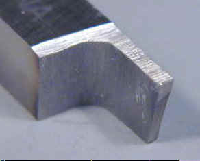
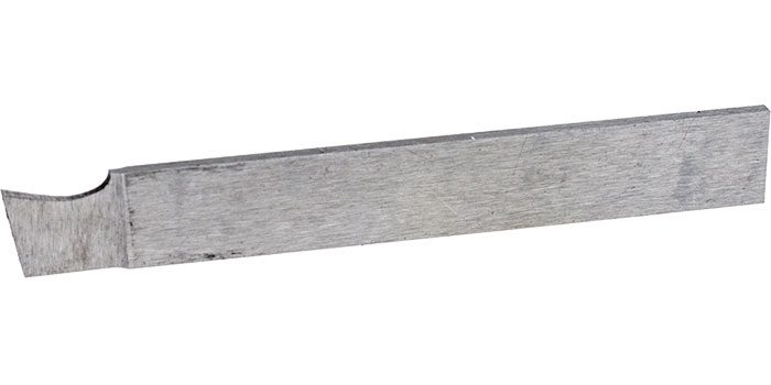
39 forum posts | I haven't done much to test all the parting tips you've given me yet. Mainly because the Arc parting tool has the blade on the wrong side so it's not possible to part less than 16mm away from the chuck which is way further than the 1/4 - 1/2" you're recommending. I've ordered a sample of EN1A steel to see if my problem is that I'm working with the wrong material. I was wrong to say that EN1A can't be zinc plated, it's only the leaded EN1A-Pb which can't be plated. Would you be able to explain whether the top side of the parting blade needs to be horizontal or at an angle? The parting tools shown on the mini-lathe.com website show blades which have a horizontal top side:
However the Arc tool and many other tools and websites recommend that there is an angle. The arc tool achieves this by having a half moon ground into the top side:
I think practically speaking a parting tool with a horizontal blade would be more convinient because if used with a quick change tool post it's height would only ever need to be set once.
|
| Philip A | 25/10/2020 11:39:21 |
39 forum posts | Just realised how stupid my point was that the blade is on the wrong side of the Arc holder. I just flipped the blade upside down and could now make the cut right by the chuck. I just successfully parted off, much better this time, but still space for improvement. What's changed since last time:
Face of the cut is still rough and chip doesn't look great but I'll work on that. |
| Mick B1 | 25/10/2020 13:52:06 |
| 2444 forum posts 139 photos | Looking at the ground HSS tool in the top pic of post 10:20:16, I'd say:- i) There doesn't look to be any back taper, so the sides will potentially rub, and ii) the top face is rough, and won't promote smooth sliding of chips off the top of the tool Tool finish and sharpness count for quite a bit when parting. I usually stone mine with a medium India oilstone. Grinding a dip for top rake has advantages for the particular component, but if you ever have to extend the tool outward to part off something of larger diameter, you have to make sure you don't go beyond the runout of the dip, or you get binding and potential chip jams there. And your tool height now demands adjustment. I use a cheap RDG partoff that holds a blade like the bottom pic, but I only grind the front face. Losing the top rake seems a lower price to pay than having to faff about with tool height or rake runout.
|
| John Baron | 25/10/2020 15:40:32 |
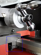
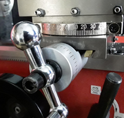
 520 forum posts 194 photos | Hi Guys, This is a picture of my rear parting tool and holder.
This parting blade is 2 mm by 12 mm by 200 mm long. The blade is parallel, no tapers anywhere. I only grind the front face to sharpen it. Whilst the post is not as rigid as it could be, its only 30 mm in diameter and really could use a block placed over it to increase the mounting area and provide a platform for height adjustment. At the moment I've just used a block under the bottom for the screw to bear against. Notice that the blade is dead square to the chuck and is inside the width of the cross slide reducing any tendency for the cutting forces to pull the tool block over and twist the slide. The biggest diameter that I've parted off so far with this setup has been 52 mm in steel. Though I must admit that since getting a 6x4 bandsaw I tend to use that in preference.
Edited By John Baron on 25/10/2020 15:42:20 |
| Philip A | 31/10/2020 08:12:04 |
39 forum posts | I just tried some of that EN1A steel you recommended, and the parting blade went through it like a hot knife through butter !! |
| Spyro Manzuffa | 17/12/2020 10:13:33 |
| 1 forum posts | Hello i stumbled upon this thread while looking on the internet. The only blade that has been working for me are those indexable SPB blades with the 2mm inserts. They require water or oil but they have been the only parting tool to work. HSS sharpened/unsharpened won't work for me. The lathe bed beneath the headstock is an open C section to house the motor and it flexed like a ******************** By chance i ended up turning a steel rod, 1 mm pass: stop cutting, the rod and cutter start to ring as per normal behavior; but i need to just press with my thumb (firmly but gently) on the headstock to remove the ring. With just the thumb you can flex the headstock up to 3/4 houndredths, if you press with the palm of the hand you end up with 15/20. So there you have it. Edited By JasonB on 17/12/2020 17:34:34 |


Please login to post a reply.
Magazine Locator
Want the latest issue of Model Engineer or Model Engineers' Workshop? Use our magazine locator links to find your nearest stockist!
Sign up to our Newsletter
Sign up to our newsletter and get a free digital issue.
You can unsubscribe at anytime. View our privacy policy at www.mortons.co.uk/privacy
Latest Forum Posts
- hemingway ball turner
04/07/2025 14:40:26 - *Oct 2023: FORUM MIGRATION TIMELINE*
05/10/2023 07:57:11 - Making ER11 collet chuck
05/10/2023 07:56:24 - What did you do today? 2023
05/10/2023 07:25:01 - Orrery
05/10/2023 06:00:41 - Wera hand-tools
05/10/2023 05:47:07 - New member
05/10/2023 04:40:11 - Problems with external pot on at1 vfd
05/10/2023 00:06:32 - Drain plug
04/10/2023 23:36:17 - digi phase converter for 10 machines.....
04/10/2023 23:13:48 - More Latest Posts...
- View All Topics
Support Our Partners


Shopping Partners
Subscription Offer

Latest "For Sale" Ads
- Reeves** - Rebuilt Royal Scot by Martin Evans
by John Broughton
£300.00 - BRITANNIA 5" GAUGE James Perrier
by Jon Seabright 1
£2,500.00 - Drill Grinder - for restoration
by Nigel Graham 2
£0.00 - WARCO WM18 MILLING MACHINE
by Alex Chudley
£1,200.00 - MYFORD SUPER 7 LATHE
by Alex Chudley
£2,000.00 - More "For Sale" Ads...
Latest "Wanted" Ads
- D1-3 backplate
by Michael Horley
Price Not Specified - fixed steady for a Colchester bantam mark1 800
by George Jervis
Price Not Specified - lbsc pansy
by JACK SIDEBOTHAM
Price Not Specified - Pratt Burnerd multifit chuck key.
by Tim Riome
Price Not Specified - BANDSAW BLADE WELDER
by HUGH
Price Not Specified - More "Wanted" Ads...
Get In Touch!
Do you want to contact the Model Engineer and Model Engineers' Workshop team?
You can contact us by phone, mail or email about the magazines including becoming a contributor, submitting reader's letters or making queries about articles. You can also get in touch about this website, advertising or other general issues.
Click THIS LINK for full contact details.
For subscription issues please see THIS LINK.
Digital Back Issues


Donate

 Register
 Log-in
Model Engineer Magazine
- Percival Marshall
- M.E. History
- LittleLEC
- M.E. Clock

ME Workshop
- An Adcock
- & Shipley
- Horizontal
- Mill

Subscribe Now
- Great savings
- Delivered to your door

Pre-order your copy!
- Delivered to your doorstep!
- Free UK delivery!
All Forum Topics > Beginners questions > Why is this guys mini lathe parting off so well?