Forum sponsored by:

Emco FB2 Quirks and Additions
| Graham Meek | 29/09/2020 17:13:12 |
| 714 forum posts 414 photos | Hi Marcel, Thanks for the update, it is nice to get some feed back that verifies the above drawing, other than just my memory. It is also good to know the Motor Pinion tooth count, as to date I have not counted this. My own mill from Austria was manufactured in1996. I was told it was one of the last to be produced, how true that is I do not know. Regards Gray, |
| Marcel Bernards | 29/09/2020 20:13:46 |
| 5 forum posts 10 photos | I learned a lot in this thread about this FB2 and clones. Love it. I made some pics to share in an album drive gear 17T i inch outer diameter
old gear 47 T Since I opened up my mill a few times and the gasgets are getting worse a drawing PDF of the top gasket would be nice. the motor gasget is a simple one. 113x113mm square with a hole of 108mm and 4 6.5mm holes 98mm square
|
| Neil Wyatt | 30/09/2020 11:58:20 |
 19226 forum posts 749 photos 86 articles | Graham has kindly sent me a PDF with a drawing of the gasket seal to upload. I changed the name to make the link simpler. You can access it here: www.model-engineer.co.uk/sites/7/documents/EMCOSEAL_GM.pdf Thanks Graham, Neil |
| Marcel Bernards | 30/09/2020 13:39:28 |
| 5 forum posts 10 photos | Fantastic, thanx Neil
|
| Michael Gilligan | 30/09/2020 14:00:55 |
 23121 forum posts 1360 photos | Posted by Neil Wyatt on 30/09/2020 11:58:20:
Graham has kindly sent me a PDF with a drawing of the gasket seal to upload. I changed the name to make the link simpler. You can access it here:
. Lovely quality image ... beats a jpg hands-down. MichaelG. |
| derek hall 1 | 30/09/2020 15:08:49 |
| 322 forum posts | Thanks Graham, Good to look at what you are doing with your Emco FB2......I will copy all of your modfications on to my FB2!
.....and thanks to Neil for the pdf Regards to all Derek
|
| Graham Meek | 30/09/2020 18:05:28 |
| 714 forum posts 414 photos | Hi Derek, I am glad you like this post, and good luck with the modifications. I have certainly learnt a few things from other contributors regarding the clones. Regards Gray, Edited By Graham Meek on 30/09/2020 18:07:50 |
| Joseph Noci 1 | 03/11/2020 21:11:06 |
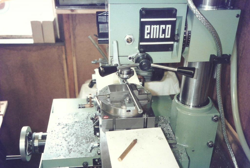
| 1323 forum posts 1431 photos | FB2 users, how do you go about tramming the mill? I need to do some rather delicate and accurate, deep , large diameter boring on the FB2, and need to tram the machine really well. I have set the column perpendicular to the table - set up an accurate refence cylinder square (100mm diameter and 200mm tall) on the table with a DTI in the spindle. Then run the head up and down with the DTI rubbing the west side of the square and adjust the column left/right. Then to repeat the process with the DTI on the South face of the cylinder square for forward/rearwards column tilt. But how best to adjust the forward/rearward tilt of the column? I did by means of paper thin spacers at top or bottom of the column support base but that is really fiddly. Is there another way? As the head can tilt left and right, I then keep the complete head in fixed position, DTO on west side of the square, and using the quill feed, run the DTI up/down the square, and adjust the 2 tilt bolts while fiddling the head vertical. Now, after doing all that, with the column pretty close to perpendicular north/south and east/west, and the head set properly vertical in east/west, I then put the usual DTI on the end of a long arm, in the spindle, and rotate the DTI over the table in a circle. Expecting a decent dial readout, I was rather disappointed...The DTI reads high (0.2mm..!) on the table surface closest to the operator, and zero on the table near the column. Left and right are equal, at around 0.08mm.... I spent most of the morning doing this, over and over....I rechecked - the column is perpendicular within 0.01mm over a 180mm height on the south and west sides of the square. I checked the square - rotating the square 90deg and 180deg shows the same 0.01mm deviation. It would appear that the spindle head ( ie, the quill and head) has some 'nod' - is 'drooping' down and I don't see how to adjust this - not in the manuals, and not evident in the parts breakdown either. Any advice will be most welcome! Joe |
| Kiwi Bloke | 04/11/2020 00:56:20 |
| 912 forum posts 3 photos | Hi Joe, Judging from the quality of your many previous posts, I'd bet that your understanding of this machine's adjustments is as good as anyone's. There is indeed no adjustment for verticality that you haven't already explored, so I suppose it would be a matter of tearing it down and checking on the surface plate, etc.. If it turns out that the quill bore and the bore for the vertical column can't be adjusted to be parallel, there's a real problem, isn't there? The lack of a proper adjustment mechanism for the column's verticality is an unfortunate omission. You could add jack screws... Just one idea, however, offered because we all have transient blind spots... Is the head carrier (or whatever it's called) clearance to vertical column really well adjusted? I thought mine was, and that chatter during some heavy boring was showing the limit of the machine. However, after tightening the clearance - to the extent that the head didn't fall unless pushed down by the raising screw, there was a vast improvement. Then had to be careful about vertical travel backlash, of course. Does the vertical travel clamp/lock affect the 'droop'? I'm sure you're aware that drilling machine tables are often aligned intentionally a little high at the operator's side, so that, under drilling forces, the hole goes (more nearly) truly vertically, as the machine springs, but I can't believe that Emco would have built in 0.2mm 'compensation' - that seems a lot (but perhaps isn't, depending on the length of the dial-carrying arm). Hope this helps. |
| Kiwi Bloke | 04/11/2020 07:21:39 |
| 912 forum posts 3 photos | ... If it turns out that the quill bore and the bore for the vertical column can't be adjusted to be parallel, there's a real problem, isn't there? ...
Sorry, badly expressed - there is no adjustment provided to correct this, but, of course, the head swivel faces can be scraped...
|
| mgnbuk | 04/11/2020 08:08:40 |
| 1394 forum posts 103 photos | Did you check the parallelism of the table top to the base casting (Y axis ways) ? Depth mic from four points from the table top to the base should give 4 near identical readings & 4 micrometer readings of table thickness should show that the table top is parallel to the X axis ways. Though as you have set the column square to the table top, the spindle trammel check suggests that the error is in the head casting joint - checking & adjusting each interface from the base casting upwards is the way that CNC machines were rebuilt at my previous employment. Knowing each stage is "right" as the machine is assembled makes it easier to track down errors as the build progresses. When it came to getting machines accepted after a rebuild, it was usual to work with the tolerances in checks - could you bias the column slightly off square to improve the trammel check ? You say that the column is within 0.01 over 180 mm - tweak it so that the 0.01 goes the opposite way & if that improves the trammel it is an overall improvement ? If you have a surface plate & 2MT test bar, take the quill carrier casting off the machine, set it on the swivel surface on the surface plate & check that the test bar is parallel (alignment of swivel face with spindle axis). If this is OK, it suggests the error is in the swivel face on the Z axis casting. If not, scrape the face to correct the error & re-check, though it may be that the error is split between the two faces. I don't know which casting has the location spigot, which can complicate doing this check - may require making up a parallel ring to get the spigot clear of the surface plate. I don't think that these machine would have had much in the way of fitting - the selling price would not allow that & what you are seeing doesn't seem to be that far out to me for this class of machine. I set the column square on my Taiwanese clone much as you have done, though I used a 150mm precision square rather than a cylinder square, and shimmed the column carrier casting as you did to get the front-back squareness. This is another joint that should really be scraped to remove the errors, but that is still on my "Round Tuit" list as the shimming doesn't seem to be causing any issues. With the column set as close as I could get it in both planes the trammel check came out "close enough", though I can't recall the exact numbers. "Close enough" being that I didn't feel the effort involved in removing the last few microns was a worthwhile use of time & the results from using the machine as it is have been acceptable for my requirements. Nigel B.. |
| Jim C | 04/11/2020 15:13:02 |
 76 forum posts 4 photos | Joseph. I have what I suppose you would call an FB2 clone in the guise of a Rishton mill (not many about by all accounts) I set the head square in the usual way using an extended DTI in the spindle and checking the table at two extreme points. You talk about doing some accurate deep boring on your mill. I am interested how you do this on a mill that has a very small quill movement and a circular column. To date I have not had a job where I could not use the lathe to do the boring and would be a bit reluctant to unlock the head of the mill and use that to bore with. I’m worried that the head will move slightly on its gib strip ?? Interested in comments from FB2 or similar mill users. Jim. |
| Graham Meek | 04/11/2020 16:49:35 |
| 714 forum posts 414 photos | Hi Joe, I have just read your post concerning the out of vertical on the column. I would be inclined to take the head off the column. Then present the cylinder square to the exposed mounting face on the Column Slider casting. I would try with the Lock/Clamp On and Off. If there is no error, move the Slider out of the way and offer the Cylinder square to the Column. You will need to raise the Cylinder square for this test on some known good parallels. As the Column casting spigot is above table height. If you have parallels long enough these could be extended such that the Cylinder square can be presented to the side of the Column at the same setting. The parallels would need to be lightly clamped to the table to counteract the weight of the Cylinder square. Provided no adjustment is needed, I would then mount the milling head on the milling machine table. Again you will need some parallels to miss the spigot on the rear mounting face. With a DTI mounted in the spindle swing over the Cylinder square. This test will prove the squareness of the mounting face. Remove the Cylinder square and insert a No 2 Morse test Mandrel in the spindle. Run a clock over the exposed plain portion. This will check the parallelism of the Quill/Spindle to the mounting face and verify the above squareness check. Some Silver Steel held in a collet and set such the any run-out is at 90 degrees to the reference test will suffice for the above test. My machine spindle dips 0.02 mm when the Column lock is released, given the overhang I can accept this. My Column adjustment is done off the machine and in use it needs to fall under it's own weight, ie, with milling head attached. Having it too tight means you get stick/slip and sudden un-explained amounts taken off. With the Column lock on the Tram North-South is -0.01 N to +0.01 S, this is over 200 mm. East-West is Zero-Zero. Hope these notes help. Regards Gray, Edited By Graham Meek on 04/11/2020 16:52:21 |
| Joseph Noci 1 | 05/11/2020 06:27:49 |
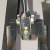
| 1323 forum posts 1431 photos | To: Kiwi Bloke, Nigel B, Jim, and Graham. Thank you for all the suggestions and advice. I spent the day yesterday working on this and used a combination of suggestions and test methods and now have the mill nicely within acceptable tram limits. I first worked on setting the 'nod' on the head assembly - I used an MT2 Test bar as suggested by Graham - Set in the spindle. the test bar parallel section is 250mm long, runout in the spindle , at the spindle end of the bar is barely evident on the DTI. At the end of the bar, furthest from the spindle, runout is half a division on the 0.01mm DTI. I set the DTI base on the column, with the DTI tip on the bottom of the test bar in North South pose, ie, to check parallelism between column and test bar when running the head up and down. North South Nod
This resulted in a half circle shim 0.008mm ( as close as I can read..) inserted in the lower hemisphere between the column sliding casting and the mill head casting. The shim extends to within 20mm of each bolt ( one left, one right) fastening the rotational mode. Ideally I should remove the head from the column casting and scrape it in, but that is a big job - remove, scrape, fit and repeat...The head is HEAVY! Next. move the DTO to the set East_West roll of the head, relative to the column. East-West Roll
The two head-roll bolts were then loosened and the head tapped into vertical, bolts fastened, re-tested, etc. The DTO was then moved back to the North_South position and nod re-checked. This since if either nod or roll are out, the DTI tip will not ride down the true axis of the test bar, but slip over the edge on the circle., so to say, with a false DTI reading. This was checked and redone a few times, till nod and roll, wrt the column, was less than a third of a DTI division or so over the 250mm test bar length. ( 1 div = 0.01mm) For reference, the head was locked on the column, and the DTI set to midway on the test bar height, set in nod mode position. The quill was then fed down to its limit, with the DTI registering no discernable deviation. The DTI was then fitted on the table, now to verify column perpendicularity to the table. Image below shows test setup for nod - North_South tilt. This required a 0.004mm shim at each top bolt, between column base and Table base. The same was done with the DTI set on the right of the test bar, for East_West.setting. Final DTI readings were less than 1/3 division. That was good enough.. North South Column Tilt
Then the last was to set the DTI on the elbow in the collet chuck in the spindle and rotate the dti over the table to check if the reading was good - Table south, 0, table north, 0.002, table east, 0, table west 0. To qualify, 0.003 is an estimate based on eyeing the needle between division - not easy! Also, a movement of 0, is not actually 'zero/' but the smallest of needle tip 'wobble' discernable. The test bar..
And its certificate..
Can someone explain the meaning of the terms on this certificate? The diameter of 30 = 30.003, ie, 0.003 error, I understand, but the rest? Now ready to start boring..! Thanks again to all. Joe |
| Joseph Noci 1 | 05/11/2020 06:39:04 |
| 1323 forum posts 1431 photos | Posted by Jim C on 04/11/2020 15:13:02:
You talk about doing some accurate deep boring on your mill. I am interested how you do this on a mill that has a very small quill movement and a circular column. To date I have not had a job where I could not use the lathe to do the boring and would be a bit reluctant to unlock the head of the mill and use that to bore with. I’m worried that the head will move slightly on its gib strip ?? Interested in comments from FB2 or similar mill users. Jim. Jim, I have always tended to use the vertical feed for boring, not the quill feed. I have not had any problems - obviously, DOC must be conservative as the round column is not that rigid to start. However, MOST important is to ensure that the column sliding casting is really snug on the column. I release the gib totally, loosen the two set screws on the right side of the casting ( impinging on the two casting compression bolts on the left side), loosen the two compression bolts, and then begin snugging them up in turn, while downfeeding the head assy. At the point where the head begins to snatch, ie, downfeed is not smooth but grabs ( ensure both compression bolts are equally 'tight' at this point). Then tighten up the two right hand set screws - they push the compression bolts out, releasing compression a little. The head should now downfeed smoothly. Then I do the same to the gib set screws. At this point boring is no problem! Run the head up and down a few times to ensure it does not grab anywhere in its travel. As to why I am doing some deep, large diameter boring, I am busy with a DIY CNC lathe - a scratch build, not a conversion, and the boring is the headstock spindle bearing assembly- I will do a post on the Lathe, so won't contaminate this thread.. Joe |
| Michael Gilligan | 05/11/2020 06:40:50 |
23121 forum posts 1360 photos | Joe, I believe the column headings in the table mean | Measure | Tolerance | Actual | MichaelG. |
| DiogenesII | 05/11/2020 07:24:22 |
| 859 forum posts 268 photos | ..and ?Taper half-angle Straightness Parallelism Diameter ..I think.. Nice, by the way.. Edited By DiogenesII on 05/11/2020 07:26:20 |
| Joseph Noci 1 | 05/11/2020 07:35:41 |
| 1323 forum posts 1431 photos | Posted by Michael Gilligan on 05/11/2020 06:40:50:
Joe, I believe the column headings in the table mean | Measure | Tolerance | Actual | MichaelG. Michael, Yes, I understood the heading, but not what they were referring to ... Thank DiogenesII - Now I know! What is the 'A' in 0.005/A - ( Angstroms..??..5nm..??) - That is one straight piece of steel... Joe |
| Kiwi Bloke | 05/11/2020 08:45:24 |
| 912 forum posts 3 photos | Joe, good to hear that you've localised the errors and taken steps to fix them - at least for the upcoming job. But you'll end up scraping the head swivel faces, won't you? Actually, I don't think it's as bad a job as you fear - measurements of lack of parallelism aren't too difficult on this fairly lightweight and easily-dismantled machine. (The head's not that heavy, and I'm considerably older than you!) You can remove the column, fit it to the head-carrying casting, place the casting's swivel-bearing face-down on a surface plate and measure between column and surface plate, and you can use your impressive test bar similarly to check parallelism of spindle to back face of the head. The bearing surface area is relatively small, as far as some machine scraping jobs go. Just to spoil everything with a damper... Have you checked for lack of head rotation about the column, as the head is fed vertically? The key, and/or its housing in the column isn't perfectly straight on my FB-2. Who said accuracy was easy? BTW, how do you get hold of things like your enviable test bar where you are? Stuff like that seems to be made from Unobtainium here in NZ... Edited By Kiwi Bloke on 05/11/2020 08:48:47 |
| Joseph Noci 1 | 05/11/2020 11:02:29 |
| 1323 forum posts 1431 photos | Posted by Kiwi Bloke on 05/11/2020 08:45:24:
But you'll end up scraping the head swivel faces, won't you? Actually, I don't think it's as bad a job as you fear - measurements of lack of parallelism aren't too difficult on this fairly lightweight and easily-dismantled machine. (The head's not that heavy,) HAH! Just to spoil everything with a damper... Have you checked for lack of head rotation about the column, as the head is fed vertically? The key, and/or its housing in the column isn't perfectly straight on my FB-2. Who said accuracy was easy? BTW, how do you get hold of things like your enviable test bar where you are? Stuff like that seems to be made from Unobtainium here in NZ... The head is more than heavy enough! Also, for fear of overdoing it, I would scrape too little, and work my way up to it - which means 3, 4, or more fit and test trials..This head will NEVER rotate again on the column, so for the medium to long term - the shim stays! Regarding head rotation around the column - that would happen if the keyway in the column was not machined straight down the side, or was unevenly worn on one edge somehow. But my tests verified the lack of a problem by default - when doing the head roll test ( East_West) with the DTI on the column, if the head spiralled down the column, it would be impossible to get a zero reading on the DTI when moving the head up and down, just by adjusting the head East_West tilt or roll. The test bar - abt 4 years ago I purchased an EMCO 14D lathe from EMCO in Austria, and as that was a huge amount of bother - on a ship for 3 months, road transport in Namibia from the harbour, etc...I though I would get ALL the accessories for the Lathe while about it - the spindle and tailstock test bars were part of it...( well , almost all accessories ..money prevented all...no taper turning attachment, and a few others..) Joe Edited By Joseph Noci 1 on 05/11/2020 11:02:52 |


Please login to post a reply.
Magazine Locator
Want the latest issue of Model Engineer or Model Engineers' Workshop? Use our magazine locator links to find your nearest stockist!
Sign up to our Newsletter
Sign up to our newsletter and get a free digital issue.
You can unsubscribe at anytime. View our privacy policy at www.mortons.co.uk/privacy
Latest Forum Posts
- *Oct 2023: FORUM MIGRATION TIMELINE*
05/10/2023 07:57:11 - Making ER11 collet chuck
05/10/2023 07:56:24 - What did you do today? 2023
05/10/2023 07:25:01 - Orrery
05/10/2023 06:00:41 - Wera hand-tools
05/10/2023 05:47:07 - New member
05/10/2023 04:40:11 - Problems with external pot on at1 vfd
05/10/2023 00:06:32 - Drain plug
04/10/2023 23:36:17 - digi phase converter for 10 machines.....
04/10/2023 23:13:48 - Winter Storage Of Locomotives
04/10/2023 21:02:11 - More Latest Posts...
- View All Topics
Support Our Partners


Shopping Partners
Subscription Offer

Latest "For Sale" Ads
- Reeves** - Rebuilt Royal Scot by Martin Evans
by John Broughton
£300.00 - BRITANNIA 5" GAUGE James Perrier
by Jon Seabright 1
£2,500.00 - Drill Grinder - for restoration
by Nigel Graham 2
£0.00 - WARCO WM18 MILLING MACHINE
by Alex Chudley
£1,200.00 - MYFORD SUPER 7 LATHE
by Alex Chudley
£2,000.00 - More "For Sale" Ads...
Latest "Wanted" Ads
- D1-3 backplate
by Michael Horley
Price Not Specified - fixed steady for a Colchester bantam mark1 800
by George Jervis
Price Not Specified - lbsc pansy
by JACK SIDEBOTHAM
Price Not Specified - Pratt Burnerd multifit chuck key.
by Tim Riome
Price Not Specified - BANDSAW BLADE WELDER
by HUGH
Price Not Specified - More "Wanted" Ads...
Get In Touch!
Do you want to contact the Model Engineer and Model Engineers' Workshop team?
You can contact us by phone, mail or email about the magazines including becoming a contributor, submitting reader's letters or making queries about articles. You can also get in touch about this website, advertising or other general issues.
Click THIS LINK for full contact details.
For subscription issues please see THIS LINK.
Digital Back Issues


Donate

 Register
 Log-in
Model Engineer Magazine
- Percival Marshall
- M.E. History
- LittleLEC
- M.E. Clock

ME Workshop
- An Adcock
- & Shipley
- Horizontal
- Mill

Subscribe Now
- Great savings
- Delivered to your door

Pre-order your copy!
- Delivered to your doorstep!
- Free UK delivery!
All Forum Topics > Manual machine tools > Emco FB2 Quirks and Additions