Forum sponsored by:

Stuart 10V Build Log - Complete Beginner...
| Dr_GMJN | 23/05/2020 21:43:37 |
 1602 forum posts | Thanks guys - that should see me through a good few steps. |
| Ron Laden | 24/05/2020 06:00:43 |
 2320 forum posts 452 photos | Posted by Dr_GMJN on 23/05/2020 17:28:17:
Still puzzling on how to make a centering bar, If you go to Stationary Engines and find my Rons Jowitt thread go to page 2 and you will see Jason's pictures of his Sprung Indicator Rod both the parts and how to set it up and use it. There is also a drawing which he kindly sent. We'll worth making, I have used mine quite a bit. I must learn how to make and add links. Ron |
| Dr_GMJN | 24/05/2020 08:34:45 |
1602 forum posts | Posted by Ron Laden on 24/05/2020 06:00:43:
Posted by Dr_GMJN on 23/05/2020 17:28:17:
Still puzzling on how to make a centering bar, If you go to Stationary Engines and find my Rons Jowitt thread go to page 2 and you will see Jason's pictures of his Sprung Indicator Rod both the parts and how to set it up and use it. There is also a drawing which he kindly sent. We'll worth making, I have used mine quite a bit. I must learn how to make and add links. Ron Thanks Ron, Jason kindly pm’d me a as link to that. I’ll put it here next time I update it. I might try making something similar today. I should also probably make adjustable saddle and cross-slide stops for the ML7 too at this point. |
| Dr_GMJN | 25/05/2020 11:57:52 |
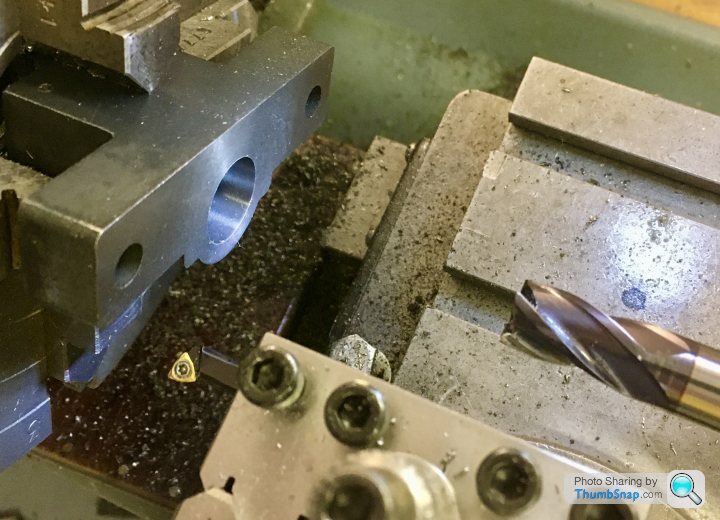
1602 forum posts | So thinking about the process of machining the bearings - I’ve got to turn bosses of different lengths on each end. It’ll be an intermittent cut from the outer ‘wings’ to the solid inner, so I’ll be moving the cross-slide in, cutting towards the Chuck, backing off, then incrementing the cross-slide in again before making another cut towards the Chuck. |
| JasonB | 25/05/2020 13:08:21 |
 25215 forum posts 3105 photos 1 articles | I just set my topslide in line with the lathe axis and use the handwheel dial to set depth, touch the end of the work, zero the dial and away you go. I only use a stop on odd occasions such as a long blind bore. I think the myford has the option to engage the half nuts and use the handle on the end of the lead screw as another option. |
| Jon Cameron | 25/05/2020 13:22:28 |
| 368 forum posts 122 photos | Posted by JasonB on 25/05/2020 13:08:21:
I think the myford has the option to engage the half nuts and use the handle on the end of the lead screw as another option. Correct however disengage the banjo and change gears first. Sounds obvious but I've done it three times now setting up to machine and broke the sheer pin on the leadscrew on my ML4, simple fix but directing I'm obviously a slow learner haha. |
| Dr_GMJN | 25/05/2020 16:09:13 |
1602 forum posts | Jason, Jon, My ML7 doesn't have dials I can zero, so I always have to remember the setting and how many turns I've backed off. If I go over the setting (or forget it), I get a step in the work. It's not great tbh. As a beginner, it's easy to turn a wheel the wrong way and really mess something up (ask me how I know!). I was going to upgrade to re-settable dials and thrust bearings, but I think I might just fit the bearings and a pair of cheap DROs (as with my mill) - everything seems so much easier with them, with no backlash to compensate for. Yes, I can engage the leadscrew half-nuts and turn the handle at the tailstock end, but then I'm trying to keep to a figure on the dial at one end, where I really want to be looking at the workpiece at the other. Anyway if my saddle stop doesn't work, I'll use the 'remember the setting' method I suppose. Building this engine really highlights what modifications would be useful to my lathe. Cheers. |
| Dr_GMJN | 25/05/2020 21:54:29 |
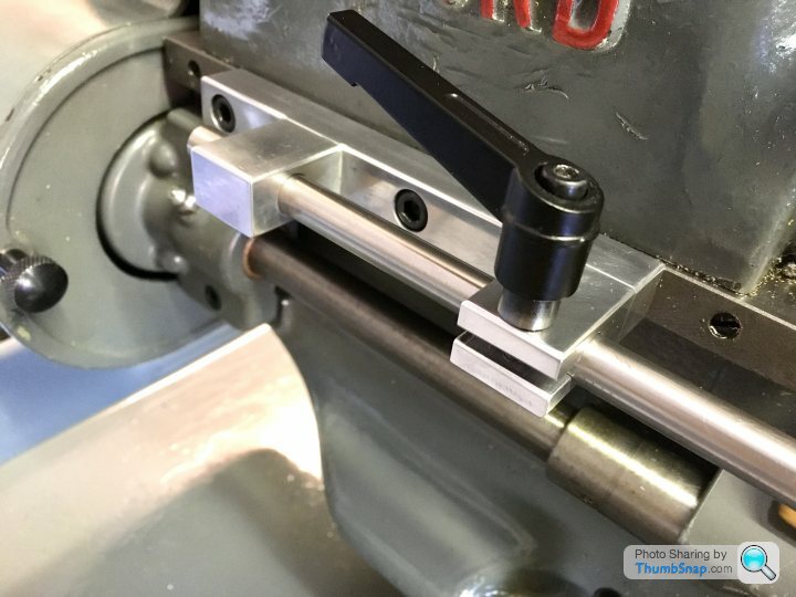
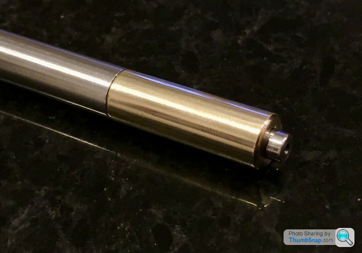
1602 forum posts | Anyway, cracked on with making a centering rod. I made it out of the remains of the 10mm silver steel I got for the spot-face tool, some brass off-cut and a random spring. I noticed Jason's version had the point sprung loaded, but I wasn't confident I could make a perfect sliding fit (no reamers); my thinking was that any play in the pointed end might interfere with the DTI reading more than if the play was at the back, because the back isn't side-loaded by the DTI. Anyway, in the end there isn't any discernable play in the plunger. Not sure about the cone angles, but I suppose I’ll see if it works soon enough on the main bearings... Cheers! |
| Dr_GMJN | 26/05/2020 22:34:06 |
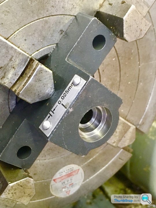
1602 forum posts | Marked out the centre of the bearing with caliper lines scribed on some blue marker. I had to use an eye loupe to get the punch central - my eyesight certainly isn't what it once was: |
| JasonB | 27/05/2020 07:06:51 |
25215 forum posts 3105 photos 1 articles | The drawing has been that way for years, new castings may be a little smaller. It's not a critical dimension so could be altered. Something like 0.2mm deep cut or to round things up nicely 10.50mm dia This is where experience over time comes in to know when you need to hit a size dead on, where it can have a bit of tolerence and where it is not critical. The easy availablity of measuring equipment these days does seem to have people looking for sizes to several decimal places where as in the past all the builder would have had was a steel rule and made just as good an engine. |
| Dr_GMJN | 27/05/2020 08:09:18 |
1602 forum posts | Posted by JasonB on 27/05/2020 07:06:51:
The drawing has been that way for years, new castings may be a little smaller. It's not a critical dimension so could be altered. Something like 0.2mm deep cut or to round things up nicely 10.50mm dia This is where experience over time comes in to know when you need to hit a size dead on, where it can have a bit of tolerence and where it is not critical. The easy availablity of measuring equipment these days does seem to have people looking for sizes to several decimal places where as in the past all the builder would have had was a steel rule and made just as good an engine. Thanks Jason - understood about the drawings - they are obviously un-toleranced, so some intuition is needed. It was just that the inner faces of the bosses form the crankshaft thrust bearings, and the brass as supplied gives you half the bearing width; 0.2mm is the drawing face width, but that leaves you with virtually no land around the boss. I might turn a spacer to clamp the boss to the mandrel, making it just small enough to get a defined land around the it, and use that as a guide for cutting. |
| paul rushmer | 27/05/2020 08:37:09 |
| 104 forum posts 17 photos | If my memory serves me correctly (its a long time ago I built mine 40 years) I used a 11mm ballnose cutter and the bearings were a brass extrusion. Andrew Smith in his book suggested using a piece of 16 SWG? sheet wrapped round the curved area and the three jaw chuck. Hope this helps. Paul |
| paul rushmer | 27/05/2020 10:42:55 |
| 104 forum posts 17 photos | My memory is not what it was, the packing used should be 0.7mm or 1/32. Hope fully I have attached the revalent page from the book. |
| JasonB | 27/05/2020 10:55:40 |
25215 forum posts 3105 photos 1 articles | Also interesting that the metric drawing gives the diameter either side as 10mm which would be more than enough to compensate for any differences in the now cast part. |
| Dr_GMJN | 27/05/2020 21:14:18 |
1602 forum posts | Thanks Paul and Jason, I have that book - I wonder why it's missing the 11mm dimension for the 7/16" block width? I've seen a couple of online builds where they've assumed the 1/4" dimension is the depth of the bearing axis below the upper surface of the block, and marked it out as such, ie with the as-cast upper surface as a datum. I don't think this is right: If the bosses are to be concentric with the semi-circular lower block, then that 1/4" below the surface will be slightly wrong. I assume it's actually the flat top face of the bearing that should be struck 1/4" up from the axis of the hole (or the lower O/D of the block). All pretty irrelevant in practical terms, but it's interesting how people interpret the drawings w.r.t. the parts they're supplied.
|
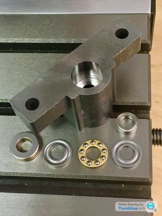
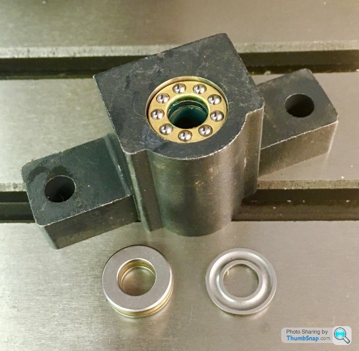
| Dr_GMJN | 27/05/2020 21:14:51 |
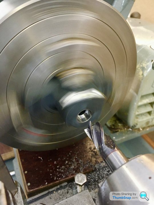
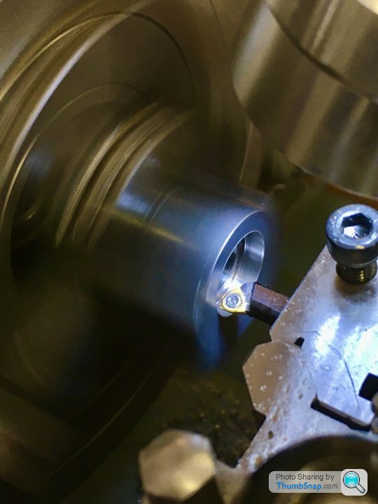
1602 forum posts | Got distracted with some modifications to the mill - I got some thrust bearings and ball races for the x & y hand wheels. As standard they have plain bushes, and metal to metal face contact on the leadscrew ends. The stiction and feel isn’t nice. ETA: It took a lot of trial and error to get to my calculated bearing step depths, cutting a bit, then using the depth gauge on my digital calipers. Even then they were a bit out. I did use my new depth stop, and the fine adjustment screw on the end. I suppose I could calibrate that if I knew the screw pitch, but it's not a great way of doing it. What's the best way of ascertaining depth when blind drilling with the tailstock feed? Mine's got a very rough scale etched onto the tailstock shaft, no good for mm work. Thanks! Edited By Dr_GMJN on 27/05/2020 21:20:28 |
| Dr_GMJN | 27/05/2020 21:16:20 |
1602 forum posts | BTW can anyone recommend a decent DCMT straight tool holder? |
| Martin Connelly | 27/05/2020 23:29:00 |
 2549 forum posts 235 photos | With a hard stop use your compound slide to set depth. With the compound in line with the ways wind it to the right. Set the stop so that the tool is close to the workpiece face when the carriage is on the stop. Wind the compound until the tool touches the workpiece and set the compound dial to zero. Move the carriage away from the stop and advance the compound by the required depth. All set to cut to the correct depth. Martin C |
| JasonB | 28/05/2020 07:12:25 |
25215 forum posts 3105 photos 1 articles | The ideal dimension would be from the underside of the two mounting lugs to the ctr of the hole as that is what ultimately sets the height relative to the A frame standard, cylinder etc. When you say straight do you mean a holder that presents the tool straight on so the insert can be used for Whit threading? Some people mount a cheap micrometer body to their depth stop or you can put a known size packer or even gauge block between stop and carriage then touch the tool to the work and when the packer is removed the tool will move in by that amount. |
| Ron Laden | 28/05/2020 07:32:56 |
2320 forum posts 452 photos | Just curious but how did you manage to use your centering bar to centre for a hole when the hole already exists, did you fit a plug or something into the hole..? |


Please login to post a reply.
Magazine Locator
Want the latest issue of Model Engineer or Model Engineers' Workshop? Use our magazine locator links to find your nearest stockist!
Sign up to our Newsletter
Sign up to our newsletter and get a free digital issue.
You can unsubscribe at anytime. View our privacy policy at www.mortons.co.uk/privacy
Latest Forum Posts
- hemingway ball turner
04/07/2025 14:40:26 - *Oct 2023: FORUM MIGRATION TIMELINE*
05/10/2023 07:57:11 - Making ER11 collet chuck
05/10/2023 07:56:24 - What did you do today? 2023
05/10/2023 07:25:01 - Orrery
05/10/2023 06:00:41 - Wera hand-tools
05/10/2023 05:47:07 - New member
05/10/2023 04:40:11 - Problems with external pot on at1 vfd
05/10/2023 00:06:32 - Drain plug
04/10/2023 23:36:17 - digi phase converter for 10 machines.....
04/10/2023 23:13:48 - More Latest Posts...
- View All Topics
Support Our Partners


Shopping Partners
Subscription Offer

Latest "For Sale" Ads
- Reeves** - Rebuilt Royal Scot by Martin Evans
by John Broughton
£300.00 - BRITANNIA 5" GAUGE James Perrier
by Jon Seabright 1
£2,500.00 - Drill Grinder - for restoration
by Nigel Graham 2
£0.00 - WARCO WM18 MILLING MACHINE
by Alex Chudley
£1,200.00 - MYFORD SUPER 7 LATHE
by Alex Chudley
£2,000.00 - More "For Sale" Ads...
Latest "Wanted" Ads
- D1-3 backplate
by Michael Horley
Price Not Specified - fixed steady for a Colchester bantam mark1 800
by George Jervis
Price Not Specified - lbsc pansy
by JACK SIDEBOTHAM
Price Not Specified - Pratt Burnerd multifit chuck key.
by Tim Riome
Price Not Specified - BANDSAW BLADE WELDER
by HUGH
Price Not Specified - More "Wanted" Ads...
Get In Touch!
Do you want to contact the Model Engineer and Model Engineers' Workshop team?
You can contact us by phone, mail or email about the magazines including becoming a contributor, submitting reader's letters or making queries about articles. You can also get in touch about this website, advertising or other general issues.
Click THIS LINK for full contact details.
For subscription issues please see THIS LINK.
Digital Back Issues


Donate

 Register
 Log-in
Model Engineer Magazine
- Percival Marshall
- M.E. History
- LittleLEC
- M.E. Clock

ME Workshop
- An Adcock
- & Shipley
- Horizontal
- Mill

Subscribe Now
- Great savings
- Delivered to your door

Pre-order your copy!
- Delivered to your doorstep!
- Free UK delivery!
All Forum Topics > Work In Progress and completed items > Stuart 10V Build Log - Complete Beginner...