Forum sponsored by:

Nalon Viper
Alum stockist
| John MC | 15/12/2019 08:49:25 |
 464 forum posts 72 photos | I've just had a look at the drawings of this engine. I think there is a problem with the way the crankshaft bearings are mounted. When the engine gets hot the aluminium bearing housing will expand approximately twice that of the steel crankshaft, therefore putting additional load on the bearings. I've looked at a few engine drawings of this type of engine and there seems to be a common theme of incorrectly mounted rolling element bearings. Unfortunately incorrect rolling bearing mounting isn't confined to these small aero engines, there are have been many designs in our "world" that have ignored the principals. In industry the principals are well very well known but sometimes ignored. A good example is bicycles. Definitely a need for some one to write about this in one of our magazines. John |
| Ramon Wilson | 15/12/2019 09:52:19 |
 1655 forum posts 617 photos | Hello Rob - Thanks for your thoughtful input. Fortunately I don't suffer with any lung problems but do notice the effect that the dust from cast iron creates - that also goes for balsa dust at the other end of the spectrum too so use a mask for most dust creating operations these days John MC - John, I'm afraid I don't see the problem as you see it. This engine design has the same bearing set up as countless others of the same make up. As the engine gets hot of course the case indeed expands but it doesn't expand inwards to create as you imply an additional load on the bearings - if anything, if the initial bearing fit is of a low order the bearing can loosen in the case. The person who designed this engine initially was a well known designer at the time and it was redrawn by another well respected person in the model engine world - all I can add is that if your observations are correct so many many manufacturers have got this wrong over many years. I perhaps should add however that my thoughts on this are based purely on practical experience and not on any specific in depth technical knowledge of bearing application per se. Nice to see some input on the subject of these small engines though
Regards - Tug
|
| john feeney | 15/12/2019 10:24:32 |
 27 forum posts 37 photos |
This is not a problem in practice. For the engines I make I bore the bearing housing about 0.001" under size, this for bearing of 19 or 22 mm outside diameter. These engines run at 16000 to 20000 rpm. There are other ways that have been used such as fitting a steel sleeve into the aluminium crankcase but even in very high performance engines the direct fitting into the aluminium is usual. There are many other aspects regarding fits in small engines which run at high speed and use only the oil in the fuel for lubrication. John Feeney |
| Ramon Wilson | 15/12/2019 12:05:42 |
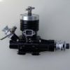
1655 forum posts 617 photos | Sorry to impinge on your thread Graham but John thats a very nice looking engine there - is that your own design and likewise the castings? Love the black finish - is it destined for any specific aeromodelling use FF or TR perhaps I've always preferred rear intake motors, don't know if you are aware but have now made several 5cc versions of early well known smaller engines. Due to lack of suitable measuring kit I usually turn and polish to a high finish a plug guage for the bearing housing. I make this 0.02mm down on desired diameter on 24/26 diameter bearings. When that just slips in the cavity the fit is just about right though may need a slight tweaking with a piece of 800 wet and dry paper if a little tight on the bearing. Tug
|
| Graham Williams 11 | 15/12/2019 12:30:03 |
| 80 forum posts 41 photos | Can only agree Tug, they do look very nice indeed, slightly green with envy as never have taken anything other than one of my bikes to that level of finish, sort of old East German functionality not Victorian splendour is how things end up for me. As to bearing fit I go with how a lot of bike bearings in gearboxes and in crankcases are usually fitted, undersize by 1.1/2thou ish, warm the casting and chill the bearing and drop them in, hope it works on this engine, we'll see. Cheers Graham W. |
| JasonB | 15/12/2019 13:19:41 |
 25215 forum posts 3105 photos 1 articles | John MC, you mentioned this before in another thread where you were commenting on axial location, from my limited use of model aero and buggy engines there is usually some end float in the crankshaft so no risk of things tightening up and adding load if the crankcase expands length ways with heat. I've a little OS 20 that is almost unused in my hand right now and that must have 0.020" endfloat. Edited By JasonB on 15/12/2019 13:21:19 |
| Ramon Wilson | 15/12/2019 15:03:11 |
1655 forum posts 617 photos | Graham - you might find 1 1/2 thou a little on the tight size on the bearing size required. I would have thought just under a thou would be fine. I usually fit the bearing to the crankshaft first then heat the case with a hot air gun nice and hot then drop the shaft in. The bearing should just drop in place in one movement. Once cooled if the bearing feels tight on the shaft then it's removed and the housing opened very slightly with wet and dry paper - a bit unscientific but always had good results so far. Tug |
| Graham Williams 11 | 15/12/2019 15:43:51 |
| 80 forum posts 41 photos | OK Tug, thanks once again. Will measure up again when I'm back in the W/Shop tomorrow and bring it to less than a thou under bearings od. and go from there. Cheers Graham W |
| Tim Stevens | 15/12/2019 17:45:01 |
 1779 forum posts 1 photos | A bearing housing will expand when hot - outwards - and exactly as much as it would if it were solid metal. As it does so, the steel bearing (or shaft) becomes a looser fit in the aluminium, and this means that the area of contact reduces slightly. So slightly, I suggest, that the effect of heat and the stesses from torque and combustion on all the other bits make the effect of minor importance. It is not, afterall, as though your model is going to be required to fly the Atlantic non-stop, is it? Cheers, Tim Edited By Tim Stevens on 15/12/2019 17:45:38 |
| John MC | 17/12/2019 08:34:32 |
464 forum posts 72 photos | Firstly my thanks to JasonB for pointing out that I am concerned with the axial location of the bearings. If the (Nalon Viper) engine could be made exactly to the (poor) drawings I've studied, additional axial load on the bearings due to incorrect constraint of the bearings (over constraint) would be applied as the engine reaches running temperature. This would be so very easy to correct and reduce the need for extremely accurate machining. If anyone is interested I will sketch the correct way to mount these bearings. This error seems to be a common theme with this type of engine that use rolling element bearings for the crankshaft support. Saying that its always been done this way and it works is not a reason to persist with poor engineering design. I've built several small "diesel" engines, those with ball bearings have all needed a small change to bearing mounting to correct what is a fundamental error. Also, it looks like the crank disc of the Nalon Viper will contact the outer, stationary member of the adjacent bearing...... John |
| Emgee | 17/12/2019 09:41:22 |
| 2610 forum posts 312 photos | Hi John I for one am interested to see your method of machining/fitting bearings in the crankcase of model engines, any improvement to performance is most welcome. Isn't it always the case there will be some contact between the disc valve and the crankcase components ? Emgee |
| JasonB | 17/12/2019 10:29:14 |
25215 forum posts 3105 photos 1 articles | John, having just had a closer look at the Viper drawings I tend to agree with you, the forward face of the crank disc is flat and will pull up against the bearing outer, other designs often have a shallow raised area so that only the bearing inner makes contact. Also a step is often provided for the taper collet to limit it's axial position as this is drawn all the force from tightening the prop nut will be pulling the bearings tightly together into their housings particularly as the larger dia of the shaft is the same length as rear bearing + gap between bearings. |
| Ramon Wilson | 17/12/2019 14:06:44 |
1655 forum posts 617 photos | When I read your post John I assumed - incorrectly - that you were referring to radial loads. As said I have no technical qualification to base comment on only practical experience. I have made several engines now as well as re-fitted bearings to quite a few commercial engines without experiencing any of the issues you show concern over. However I've always fitted my front bearings with a minimal end float in the housing as they are, as Jason suggests, clamped between a step on the shaft and the prop driver/collet. Sometimes if the tolerances are awry on commercial engines then the bearings will clamp up as said - this usually requires a deepening of the front housing or a shim behind the front bearing - the front bearing should be set such to have a degree of float All I can add is that I have operated these small engines since the age of thirteen but, it has to be said never as a high end competition user where issues that you raise would no doubt be of note. Now approaching seventy five, I am, never the less, a very firm believer in that you can learn something every day so would be most interested in any information that you would care to impart on the matter It is sometime since I looked at Ron Cherniches drawings for the Viper - I believe these are the only ones available. The web of course should not bear on the outer face but on a smaller diameter raised area as Jason points out. In his defence Ron was a died in the wool dedicated small engine pesron who did many drawings - inevitably mistakes occur - I know Jason has always found the ones on mine Regards - Tug |
| JasonB | 17/12/2019 15:18:52 |
25215 forum posts 3105 photos 1 articles | Viper drawings for those interested |
| Ramon Wilson | 18/12/2019 12:05:03 |
1655 forum posts 617 photos | Thanks Jason been a while since I looked at those. I see Ron has drawn the make up of shaft to case without any tolerances or allowance, the main shaft length dimensionally the same as the case length plus rear bearing. I think it fair to say that anyone intending to make one of this type of engine would soon see that either the main portion of the shaft needs to be extended or the case width between bearings reduced at the front end slightly (5 thou ish) should more than suffice. I revisited Rons site - his discourse on the Viper is here . I believe this was in his latter days and quite ill, perhaps that goes some way to explain his error. Tug Edit - I just found that the link does not go to the respective page - Select 'Engines' then 'Finder' in the left hand menu and scroll down to Nalon Viper Edited By Ramon Wilson on 18/12/2019 12:09:49 Edited By JasonB on 18/12/2019 12:24:50 |
| JasonB | 18/12/2019 12:22:54 |
25215 forum posts 3105 photos 1 articles | yes indeed Ramon quite likely one of the last engines that he drew and we don't know what info was on Eric's sketches that he worked from. But at least we have the engine as drawn and many others too thanks to Ron which may otherwise have become lost. I see that the photo's on MEN site of Norman Long's engine show the raised area at the front of the crank web so only contact with the bearing inner , also a second diameter to the crankshaft that may have given something for the front bearing inner to bear against or it was longer and the tapered collet tightened against teh extra shoulder giving the end float so the bearings wre not "tightened" as the crankcase warmed up. Also shows long SLOTTED screws for the head/cylinder.
Edited By JasonB on 18/12/2019 12:30:20 |
| Emgee | 18/12/2019 13:14:03 |
| 2610 forum posts 312 photos | The raised area on the shaft to prevent interference with the bearing outer is shown as .375" diameter on the front view of the shaft but not on the side view. May have to get some al block cut up to get on with the build. Emgee |
| Graham Williams 11 | 18/12/2019 14:10:03 |
| 80 forum posts 41 photos | Blimey, I only asked about suitable alum spec lol. but greatful for all the knowledgable input. Hadn't twigged any issue with crank to rear bearing, note to self, read drgs more thoroughly, but believe it's something that I can do fairly easily. The 'photos from the MEN site are of a Mk 2 whose cylinder/head were much different to the Mk1, Drgs and 'photos show csk slotted screws as Jason points out but I've managed to get both cheese head and cap screws of the right length in 6BA for my Mk1, will probably use the allen pins as they match the front and rear housing screws which I have quite a few of. Cheers Graham W |
| JasonB | 18/12/2019 14:54:03 |
25215 forum posts 3105 photos 1 articles | Posted by Emgee on 18/12/2019 13:14:03:
The raised area on the shaft to prevent interference with the bearing outer is shown as .375" diameter on the front view of the shaft but not on the side view. It think you are wrong there. The rear bearing is 3/8" ID and the dimension you are looking at is that of the 0.692" length of shaft. Inside that you have the smaller 1/4" solid circle for the smaller bearing to fit and the dotted circle is the minor dia of the 1/4" BSF thread. Edited By JasonB on 18/12/2019 14:55:08 |
| John MC | 18/12/2019 17:10:13 |
464 forum posts 72 photos | I've attached a sketch of how the bearings should be mounted. This is for a rotating shaft, stationary housing. The bearings are clamped to the shaft by the nut on the end of the shaft. the order being nut, washer, flywheel (or prop driver), brg. inner race, spacer, brg. inner race and crankshaft. Note the crank shaft reduces in diameter before the end of the brg. inner race. Hopefully it will be self evident from the sketch that there is clearance for one of the outer races to move axially, the fit in the housing would be a transition fit. The other bearing is the locating bearing. The outer race is against an abutment formed in the housing and held in position with a circlip. I've suggested a circlip but there are other ways. Always best to use the bearing manufacturers recommendations for fits. This arrangement will stop axial loading caused by differential expansion of the various components. Also will greatly reduce the accuracy requirements for the various axial lengths. Look at any well designed assembly (ball bearings/rotating shaft) and this is how it will be done. If the housing rotated then the mounting would be a little different. Over constraint of the bearings, as the are with the Nalon Viper, is a common reason for bearing failure, often mistaken for other problems. The whole business of rolling element bearing mounting is drummed in to students of mechanical engineering, some still get it wrong or choose to ignore these basic principles with the inevitable consequences..... John
|
.jpg")
.jpg")
.jpg")


Please login to post a reply.
Magazine Locator
Want the latest issue of Model Engineer or Model Engineers' Workshop? Use our magazine locator links to find your nearest stockist!
Sign up to our Newsletter
Sign up to our newsletter and get a free digital issue.
You can unsubscribe at anytime. View our privacy policy at www.mortons.co.uk/privacy
Latest Forum Posts
- hemingway ball turner
04/07/2025 14:40:26 - *Oct 2023: FORUM MIGRATION TIMELINE*
05/10/2023 07:57:11 - Making ER11 collet chuck
05/10/2023 07:56:24 - What did you do today? 2023
05/10/2023 07:25:01 - Orrery
05/10/2023 06:00:41 - Wera hand-tools
05/10/2023 05:47:07 - New member
05/10/2023 04:40:11 - Problems with external pot on at1 vfd
05/10/2023 00:06:32 - Drain plug
04/10/2023 23:36:17 - digi phase converter for 10 machines.....
04/10/2023 23:13:48 - More Latest Posts...
- View All Topics
Support Our Partners


Shopping Partners
Subscription Offer

Latest "For Sale" Ads
- Reeves** - Rebuilt Royal Scot by Martin Evans
by John Broughton
£300.00 - BRITANNIA 5" GAUGE James Perrier
by Jon Seabright 1
£2,500.00 - Drill Grinder - for restoration
by Nigel Graham 2
£0.00 - WARCO WM18 MILLING MACHINE
by Alex Chudley
£1,200.00 - MYFORD SUPER 7 LATHE
by Alex Chudley
£2,000.00 - More "For Sale" Ads...
Latest "Wanted" Ads
- D1-3 backplate
by Michael Horley
Price Not Specified - fixed steady for a Colchester bantam mark1 800
by George Jervis
Price Not Specified - lbsc pansy
by JACK SIDEBOTHAM
Price Not Specified - Pratt Burnerd multifit chuck key.
by Tim Riome
Price Not Specified - BANDSAW BLADE WELDER
by HUGH
Price Not Specified - More "Wanted" Ads...
Get In Touch!
Do you want to contact the Model Engineer and Model Engineers' Workshop team?
You can contact us by phone, mail or email about the magazines including becoming a contributor, submitting reader's letters or making queries about articles. You can also get in touch about this website, advertising or other general issues.
Click THIS LINK for full contact details.
For subscription issues please see THIS LINK.
Digital Back Issues


Donate

 Register
 Log-in
Model Engineer Magazine
- Percival Marshall
- M.E. History
- LittleLEC
- M.E. Clock

ME Workshop
- An Adcock
- & Shipley
- Horizontal
- Mill

Subscribe Now
- Great savings
- Delivered to your door

Pre-order your copy!
- Delivered to your doorstep!
- Free UK delivery!
All Forum Topics > I/C Engines > Nalon Viper