Forum sponsored by:

Myford super 7 Positioning servo's on Spindle and main infeed
Complete rebuild and conversion.
| Michael Gilligan | 18/12/2018 15:34:38 |
 23121 forum posts 1360 photos | That's looking good, Andrew MichaelG. |
| Hopper | 19/12/2018 07:03:57 |
 7881 forum posts 397 photos | Posted by Andrew Davies 4 on 04/10/2018 21:49:13:
A question How do I stop the new shim on the rear vertical slide moving on the conversion. I have seen a person using super glue. is this a real solution? Would I use carbon steel or brass shim? Andrew I used ground steel gauge plate 1/16" thick on mine. Available in half-inch wide strips, just right. Thickness needs to be more than the existing gap you can measure there (at both ends) so it moves the saddle back off the front shear. This means apron/halfnut /leadscrew alignment will need to be adjusted to suit. I secured the gauge plate strip by two dowel pins about 3/16" diameter, holes drilled and reamed through the saddle and strip while all clamped together. Strip was then retained with Loctite for good measure, and easy assembly. I would not trust adhesive alone to hold on for the next 50 years, hence the dowels as well. Dowels were just bits of common silver steel rod. Once you have done the wide guide conversion, you can remachine the inner vertical surface of the front shear so it guides the tailstock truly without loose and tight spots. This operation can be done by running the saddle back and forth by hand, using the wide guide conversion to keep it running true. A vertical slide can be attached to the cross slide and long piece of half-inch square HSS ground like a shaper toolbit (or a lathe toolbit turned sideways in effect) can protrude downwards and remachine the shear surface like a planer as it goes back and forth. Depth of cut is determined by the cross slide, feed by the vertical slide. If you wanted to get really particular, you could finish off with a Dremel or similar grinder in place of the HSS toolbit. However, I found the hand-planing method gave a very nice finish on the cast iron with a light cut, quite good enough for the job of guiding the tailstock. Knock the sharp edges off with a 10" single cut mill file etc. Neil has a couple of articles on file for both these operations, so they may appear in MEW at some point. |
| Andrew Davies 4 | 20/12/2018 10:00:05 |
 49 forum posts 56 photos |
|
| Andrew Davies 4 | 20/12/2018 10:02:13 |
49 forum posts 56 photos | Really pleased with the the resprayed cabinet.
|
| Andrew Davies 4 | 20/12/2018 10:02:47 |
49 forum posts 56 photos |
|
| Andrew Davies 4 | 20/12/2018 16:25:37 |
49 forum posts 56 photos | Looking more like a real one
|
| Niels Abildgaard | 20/12/2018 18:05:48 |
| 470 forum posts 177 photos | I am following because I have dreamt of eletronis screwcutting and cone making for Years. I had a Myford 7 with a friend more than fifty years ago He is still using it at home https://www.youtube.com/watch?v=3j00T-fhvvc. My granite based Boxford got a new home in his summer cottage and he says it is a better lathe than the Myford. Sounds better,nicer surface etc. https://www.youtube.com/watch?v=DeFLeNPhqDY A canadian followed my advice and put his Myford on a big block of concrete.Very systematic guy so he made a cut before movement and one after; same piece of material same tool etc.Nigth and day finish. If it is not to much bother can You please put the cabinet bottom up and photograph the underside of the lathe mount plate and surroundings? .My friend and I and associated women are not so young anymore and his Myford is kind of caged in. If I have a picture of Yours I think I can persuade him to liberate cabinet,fill the top from inside with crushed stone -epoxy mix and then his Myford will turn better than my former Boxford.Very important this.
Edited By Niels Abildgaard on 20/12/2018 18:07:27 |
| Andrew Davies 4 | 20/12/2018 18:31:01 |
49 forum posts 56 photos | Hi It will be very difficult to turn upside down. When I was cleaning the base up, I realised the top slides vertically off, hence the small bolts in each corner. There are heavy plates under the plate steel top for stability. In my opinion you have to know when to stop, after all this is a Myford 7 and always will be. I have taked many photos whilst carrying out the renervation, a lot of these are in my album, I have many more if you have a particular area of interest. Unfortunately I do not have a photo with the top plate removed. I still think I have about 200 hours to completely finish the project and complete all the software. Andrew
|
| Niels Abildgaard | 20/12/2018 22:07:24 |
| 470 forum posts 177 photos | Hello Andrew Thank You for explanation. I thougth it was a standard thin-plate top cabinet that can surely be made more rigid. There is someone not so far from here who has an old Myford and I will go with my phone and make a picture from floor level and up against the standard top plate. Good luck and we are, I think,many who want to read about it. Edited By Niels Abildgaard on 20/12/2018 22:09:56 |
| Andrew Davies 4 | 20/12/2018 22:24:30 |
49 forum posts 56 photos |
They show an extra plate to the right and left |
| Andrew Davies 4 | 21/12/2018 06:45:08 |
49 forum posts 56 photos |
Starting to look more like a lathe. Edited By Andrew Davies 4 on 21/12/2018 06:47:17 |
| Andrew Davies 4 | 09/01/2019 22:42:49 |
49 forum posts 56 photos | Just sent drawings off to have spindle plate made. |
| Andrew Davies 4 | 09/01/2019 22:49:54 |
49 forum posts 56 photos | As you will see from the attached, I am an electrical engineer, but the drawings work. This is the main spindle cutter plate. I have also got a few other bits comming. Still about 100 hours of work before I cut gears.
|
| Andrew Davies 4 | 09/01/2019 22:55:22 |
49 forum posts 56 photos | HMI now fitted
|
| Michael Gilligan | 09/01/2019 23:00:56 |
23121 forum posts 1360 photos | Nice MichaelG. |
| David George 1 | 10/01/2019 13:36:47 |
 2110 forum posts 565 photos | Looking good please keep the pictures and progress coming. David |
| Andrew Davies 4 | 10/01/2019 17:53:55 |
49 forum posts 56 photos |
Please see attached pics. |
| Andrew Davies 4 | 10/01/2019 18:17:47 |
49 forum posts 56 photos | Someone has asked what paint I used. Please see attached pics. The main paint was great both for brush and spray. Edited By Andrew Davies 4 on 10/01/2019 18:20:58 Edited By Andrew Davies 4 on 10/01/2019 18:23:53 |
| Andrew Davies 4 | 10/01/2019 18:19:59 |
49 forum posts 56 photos | Hi David
Looked at you profile. We come from similar background on engineering,but mine is electronic. I also have a bike, Triumph street triple R, that is loved and cared for...... All the best Andrew |
| Andrew Davies 4 | 15/01/2019 20:55:58 |
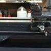
49 forum posts 56 photos | This has been a long research and strange conclusion. As the MT 1 taper cutter holder is going to be vertical, I wanted a nut that will hold the cutter shaft in place. The cutter shaft is being machined from an existing MT1 taper avaliable on the internet. I need a nut to thread on the end of the sherline head stock that would hold the shaft, my extensive research found nothing. I went into my garage and looked through my plumbing fittings and found that a 15mm compression fitting fitted the head stock!!
Perfect! Edited By Andrew Davies 4 on 15/01/2019 20:57:48 |


![img_2164[1].jpg](/sites/7/images/member_albums/173731/819511.jpg "img_2164[1].jpg")
![img_2163[1].jpg](/sites/7/images/member_albums/173731/819510.jpg "img_2163[1].jpg")


Please login to post a reply.
Magazine Locator
Want the latest issue of Model Engineer or Model Engineers' Workshop? Use our magazine locator links to find your nearest stockist!
Sign up to our Newsletter
Sign up to our newsletter and get a free digital issue.
You can unsubscribe at anytime. View our privacy policy at www.mortons.co.uk/privacy
Latest Forum Posts
- *Oct 2023: FORUM MIGRATION TIMELINE*
05/10/2023 07:57:11 - Making ER11 collet chuck
05/10/2023 07:56:24 - What did you do today? 2023
05/10/2023 07:25:01 - Orrery
05/10/2023 06:00:41 - Wera hand-tools
05/10/2023 05:47:07 - New member
05/10/2023 04:40:11 - Problems with external pot on at1 vfd
05/10/2023 00:06:32 - Drain plug
04/10/2023 23:36:17 - digi phase converter for 10 machines.....
04/10/2023 23:13:48 - Winter Storage Of Locomotives
04/10/2023 21:02:11 - More Latest Posts...
- View All Topics
Support Our Partners


Shopping Partners
Subscription Offer

Latest "For Sale" Ads
- Reeves** - Rebuilt Royal Scot by Martin Evans
by John Broughton
£300.00 - BRITANNIA 5" GAUGE James Perrier
by Jon Seabright 1
£2,500.00 - Drill Grinder - for restoration
by Nigel Graham 2
£0.00 - WARCO WM18 MILLING MACHINE
by Alex Chudley
£1,200.00 - MYFORD SUPER 7 LATHE
by Alex Chudley
£2,000.00 - More "For Sale" Ads...
Latest "Wanted" Ads
- D1-3 backplate
by Michael Horley
Price Not Specified - fixed steady for a Colchester bantam mark1 800
by George Jervis
Price Not Specified - lbsc pansy
by JACK SIDEBOTHAM
Price Not Specified - Pratt Burnerd multifit chuck key.
by Tim Riome
Price Not Specified - BANDSAW BLADE WELDER
by HUGH
Price Not Specified - More "Wanted" Ads...
Get In Touch!
Do you want to contact the Model Engineer and Model Engineers' Workshop team?
You can contact us by phone, mail or email about the magazines including becoming a contributor, submitting reader's letters or making queries about articles. You can also get in touch about this website, advertising or other general issues.
Click THIS LINK for full contact details.
For subscription issues please see THIS LINK.
Digital Back Issues


Donate

 Register
 Log-in
Model Engineer Magazine
- Percival Marshall
- M.E. History
- LittleLEC
- M.E. Clock

ME Workshop
- An Adcock
- & Shipley
- Horizontal
- Mill

Subscribe Now
- Great savings
- Delivered to your door

Pre-order your copy!
- Delivered to your doorstep!
- Free UK delivery!
All Forum Topics > CNC machines, Home builds, Conversions, ELS, automation, software, etc tools > Myford super 7 Positioning servo's on Spindle and main infeed