Forum sponsored by:

Electronic Artisans ELS Article
| John Stevenson | 26/03/2016 12:22:25 |
 5068 forum posts 3 photos | Any Pugh is a very, very, accomplished programmer. What I'd call formidable.
Now get Joe Blogs in the street to load this into Ubuntu and get it running. Btw on the next to last page in a post from Andy it says "These macros don't produce any G-code. Each operation runs a pre-programmed routine with different parameters.
So not sure if it works or just looks good.
Contary to popular opinion I am not bashing Linux, in fact the opposite. I want the community to see that there is a market for just users. It's hard though. In fact Andy, in another thread is genuinely curious why someone wants to use the Tormach screen over what is available.
It's down to use, familiarity and perception. Most modern controllers look very similar and for a purpose. The skill pool of users to operate this machines isn't endless and making them similar means users can swap between machines / jobs without expensive retraining.
Now when I show prospecting users these Linux CNC screens with the exception of two the rest don't even have start stop buttons and modifying a screen isn't drag and drop but requires someone with formidable programming skills.
This is fact because I believe in chequebook engineering, you get where you want to go far faster. When my gear hobber broke down I knew it could get got up and running on Linux. In fact the Formidable Andy Pugh has done exactly what I wanted and has a you tube video on it. So a local Linux Guru was contacted, Hi Dave It works well, it wasn't easy even the guru had problems but it works and all this does it run one axis and has two rev counters slapped in the middle of the screen, one for hob sped and one for work speed. Certainly not a product you would sell on looks.
So long short is there will always be programmers and people who want to play. There will always be users and people who want to use machines to make what they want There will be people like Tormach, who want a package they have control over for support issues
Unfortunately these three categories cannot overlap, each wants a specific use. |
| Mark P. | 26/03/2016 17:21:03 |
 634 forum posts 9 photos | If I wanted to fit an ELS to my lathe just for screw cutting, is there a simple programme that I could use with a laptop without using the controller as shown in the artical? Mark .p |
| Alan Jackson | 26/03/2016 18:38:07 |
 276 forum posts 149 photos | Mark You can use TurboCNC which is a Dos program you can download, it will work from an older laptop with a printer port. It requires a spindle sensor showing one pulse per rev and a stepper motor and driver. I use it on my Stepperhead lathe and it works very well. It does not have the luxury of the more sophisticated systems mentioned on this thread but it is very suited to model engineers etc. I described it in more detail on my Stepperhead articles. Here it is on utube, you can hear a slight speed variation but this should not be of any real concern in most circumstances. https://www.youtube.com/watch?v=ZH0ZjWauMZ0&feature=channel&list=UL Alan |
| John Stevenson | 26/03/2016 22:51:57 |
5068 forum posts 3 photos | Mark and anyone else that is still following the practical side of this conversation instead of the theoretical "I may well do it one day " Then Weston Bye who writes for Home shop machinist put together a stand alone ELS a while ago that is interesting to read.
http://bbs.homeshopmachinist.net/threads/42769-Electronic-Threading-my-method
Clickable link added. Edited By John Stevenson on 26/03/2016 22:52:36 |
| Michael Gilligan | 26/03/2016 23:18:37 |
 23121 forum posts 1360 photos | Posted by John Stevenson on 26/03/2016 22:51:57:
Mark and anyone else that is still following the practical side ... . Thanks, John
MichaelG. |
| Ajohnw | 27/03/2016 00:29:31 |
| 3631 forum posts 160 photos | Posted by John Stevenson on 26/03/2016 22:51:57:
Mark and anyone else that is still following the practical side of this conversation instead of the theoretical "I may well do it one day " Then Weston Bye who writes for Home shop machinist put together a stand alone ELS a while ago that is interesting to read.
Clickable link added. Edited By John Stevenson on 26/03/2016 22:52:36 Dear Dear, Toys out of pram etc. People might find the electronic method I mentioned earlier interesting. John - |
| Michael Gilligan | 27/03/2016 08:54:27 |
23121 forum posts 1360 photos | Ajohnw, Perhaps I am missing some 'programmers joke' but I really do not understand your last outburst. JohnS has provided a link to something that is comprehensible, and I [for one] am grateful. The details [mechanical and electronic] may or may not prove to be directly transferable; but I like the concept. I particularly like his starting-point: [quote] To do this I had to start with a sufficiently large pulse count per revolution of the spindle – in the case of my equipment, 8000 pulses per spindle revolution. [/quote] ... I think that thread should prove to be genuinely educational. MichaelG. Edited By Michael Gilligan on 27/03/2016 08:56:49 |
| Mark P. | 27/03/2016 09:58:43 |
634 forum posts 9 photos | Thanks for the replies I will have a look at the links and dig out the old copies of MEW. Regards Mark P. |
| Ajohnw | 27/03/2016 11:27:39 |
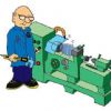
| 3631 forum posts 160 photos | There is some practical information around on a different method of making an ELS. This is the basic details What a metric implementation can do
And a rough schematic
The original article is here giving details of how the "ratios" are achieved. The gearbox is just motor speed reduction. More on the yahoo group. As is often the case there doesn't seem to be much info on how well it works and it uses as servo motor to drive the lead screw - that means a low inertia motor is probably needed according to some leaving the question of how low. There is also some detail of an attempt to replace the motor with a stepper. Not enough to see how well that went but there could be other methods. John -
|
| John Stevenson | 27/03/2016 12:34:00 |
5068 forum posts 3 photos | Posted by Michael Gilligan on 27/03/2016 08:54:27:
I particularly like his starting-point: [quote] To do this I had to start with a sufficiently large pulse count per revolution of the spindle – in the case of my equipment, 8000 pulses per spindle revolution. [/quote] ... I think that thread should prove to be genuinely educational. MichaelG. Edited By Michael Gilligan on 27/03/2016 08:56:49 Michael,
I can see where he's coming from with the high count. The principle is pretty simplistic and is just an electronic system of gearing where one ratio uses the full count even if sub divided by a reduction head or micro stepping and then subsequent ratios are further divided from that.
If you don't start high enough you run out of pulses at the higher divisions.
When I built my Electronic Hobbing machine I worked closely with Brian Thompson on this who published his results in MEW 108. We started off at 4,000 counts, in my case it was a standard 1024 encoder geared up 125:32 It then went thru a divide by chip with thumb wheels setting the number of teeth needed. It worked and worked well, I have no idea how many gears were cut with this as it stood but it literally had to be in the thousands.
It was virtually the same as an ELS and could have been made as such with a few mods to overcome design flaws.
Because it used only one channel of the encoder and no index it could only count one way irrespective of the way the hob was running. Turn the hob forward and the blank moved forward, turn the hob back and the blank still moved forward.
This meant every gear had to be done in one pass as a second cut couldn't be guaranteed to follow the previous pass. In my case this wasn't a problem as the machine doing the cutting, a modified Victoria U2 was more than man enough for gears with of DP of 16 and upwards.
When after quite a few years it started to give problems then the move to LinuxCNC was already in the wings and hardware and experts lined up ready and waiting.
If I wanted an ELS today what I would do is get the hardware which is basically a power supply, stepper driver and motor and a multi line encoder and a small board called a BeagleBone Black which is similar to a Raspberry Pi but more capable and runs Linux. I would then find and pay a guru to make this all work as I realise my limitations.
It worked for me on the gear hobber. I can now cut course DP gears with as many passes as I require. It's also working for me on another project I don't want to mention at this point with another Linux guru who has a different area of expertise.
The secret in these projects though is WANTING to do them, not just being interested because there are people on the various forums all too willing to detract you.
On the Mach3 forum, when mach3 was being evolved I lost count of the people says they could do this, do that etc etc and most never came up with the goods. This even included commercial concerns that soon realised they they either couldn't meet the target or they had bit off more than they could chew. These are the Dementors of forums, sucking the life blood away whilst never, ever giving anything back. |
| John Haine | 27/03/2016 13:08:24 |
| 5563 forum posts 322 photos | Regarding gear hobbing, has anyone applied the obvious solution of a phase locked loop to multiply up the pulse count from the spindle? The ubiquitous 4046 CMOS chip plus an external divide by N can multiply the M counts per rev up to NxM, for subsequent division by whatever ratio you need to drive the hob. In effect an electronic gear-up. Seems to me much easier than finding a high count encoder, adding quadrature combination to get x4, and then possibly adding mechanical gears. Could use a one pulse per rev Hall effect sensor and a 4096 divider, which is 2 to the power 12, to get JS' 4000 pulses per rev. |
| Michael Gilligan | 27/03/2016 13:49:42 |
23121 forum posts 1360 photos | Posted by Ajohnw on 27/03/2016 11:12:40:
Posted by Michael Gilligan on 27/03/2016 08:54:27:
Ajohnw, Perhaps I am missing some 'programmers joke' but I really do not understand your last outburst.
Your initial comment was rather rude and pointless. Rather like your comments on Brians thread. The only reason I mentioned how I would go about it due to odd comments I have seen at times by people who are trying to do it. I was just pointing out that it's worth seeing what the goal posts need to be before starting. John - . John, My inital comment was simply an honest reaction to your "Toys out of pram" post [which seemed totally inappropriate] ... and, by the way, I am not aware of it being "rather like" any of my comments on 'Brians thread' (sic). ... Please feel free to send me details, by PM MichaelG. Edited By Michael Gilligan on 27/03/2016 13:50:30 |
| Michael Gilligan | 27/03/2016 14:04:20 |
23121 forum posts 1360 photos | Posted by John Stevenson on 27/03/2016 12:34:00:
Michael, I can see where he's coming from with the high count. < etc. > . Thanks for the notes, John Yes, me too ... it was not so much a revelation, as an endorsement of my own opinion. [ which is probably why I quoted it Too many of the other proposals seem to start with one pulse per rev of the headstock spindle ... and surely that is is going to make hard work of everything that follows. MichaelG. Edited By Michael Gilligan on 27/03/2016 14:06:28 |
| Ajohnw | 27/03/2016 14:56:34 |
| 3631 forum posts 160 photos | Posted by John Haine on 27/03/2016 13:08:24:
Regarding gear hobbing, has anyone applied the obvious solution of a phase locked loop to multiply up the pulse count from the spindle? The ubiquitous 4046 CMOS chip plus an external divide by N can multiply the M counts per rev up to NxM, for subsequent division by whatever ratio you need to drive the hob. In effect an electronic gear-up. Seems to me much easier than finding a high count encoder, adding quadrature combination to get x4, and then possibly adding mechanical gears. Could use a one pulse per rev Hall effect sensor and a 4096 divider, which is 2 to the power 12, to get JS' 4000 pulses per rev. The divider can also be set pretty easily to different ratio's. An example of that approach is the other style of els I posted a link to. John - |
| John Stevenson | 27/03/2016 15:29:37 |
5068 forum posts 3 photos | Posted by Michael Gilligan on 27/03/2016 14:04:20:
Posted by John Stevenson on 27/03/2016 12:34:00:
Michael, I can see where he's coming from with the high count. < etc. > . Thanks for the notes, John Yes, me too ... it was not so much a revelation, as an endorsement of my own opinion. [ which is probably why I quoted it Too many of the other proposals seem to start with one pulse per rev of the headstock spindle ... and surely that is is going to make hard work of everything that follows. MichaelG. Edited By Michael Gilligan on 27/03/2016 14:06:28 .
Precisely.
Back in December 2008 Art added multiline encoders to Mach 3 for one version only but it was withdrawn quickly as it didn't work. Remember Mach 3 was always a work in progress with two versions, one an earlier one that was the production version and was the best up to that point, and a later beta version is when everything went right would replace the production version at some point.
During this period I did a lot of development work with Art on this trying to sort the problems out. I probably spent a whole week on this virtually full time. Emails from this period prove that a lot was being done and Art worked tireless on this one, often with a new version within a few hours, no mean feat.
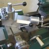
My version of turn looked nothing like the standard on. It had possibly 10? extra DRO boxes that could keep count what was happening and allow me to video the screen so Art could also see. Art didn't have a lathe capable of heavy screwcutting at this point.
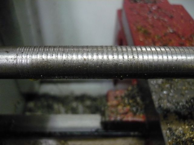
Some photo's from that era
This is a classic one, starts off well but the longer it goes and the more passes the bigger the lead error.
This is all down to the single line index getting out of sync and windows not being real time, never managing to get it under control.
It could be better, in fact the big boys with 10 HP spindle motors didn't have this problem because threading isn't a high torque operation on a CNC and if you have 1/2 a tonne of spindle and headstock gears spinning around you are not going to vary speed. But if a small lathe can thread OK so everything else will follow.
The answer is to pass the threading instructions to an outside card but then the problems are who will invest in such a card for such a small return on capital as lathe users are well in the minority to mill uses and many are on Linux anyway.
Mach 4 is in the same boat, in fact it's worse in that Mach 3 had the parallel port controller built in whereas Mach 4 is a dumb controller and relies on paid external support to run anything, even the parallel port. |
| Ajohnw | 27/03/2016 16:34:07 |
| 3631 forum posts 160 photos | Did slip compensation and or V/F control via an inverter make any difference John? It is aimed at this sort of problem but I would wonder if it's fast and accurate enough. John - |
| John Stevenson | 27/03/2016 17:39:55 |
5068 forum posts 3 photos | ??????????????
Sorry that makes no sense to me what so ever.
Can't be slippy, I'd swept up and no VFD fitted, in fact you can't fit one. |
| Ajohnw | 27/03/2016 18:42:25 |
| 3631 forum posts 160 photos | Whoops I assumed that you would have an inverter driving the lathes main motor. In terms of maintaining speed as the loads change inverters have improved from early days but I'm not sure if they are up to this sort of thing. Should add that they can have 2 basic modes volts frequency or constant torque. VF best for varying loads and also slip control which is supposed to improve it still further. John - Edited By Ajohnw on 27/03/2016 18:49:44 |
| John Stevenson | 27/03/2016 19:23:04 |
5068 forum posts 3 photos | Right, with you now and this is the last thing you want. One one hand you have a semi closed loop between the spindle encoder and the controller. I say semi as it relies on the one pulse per rev.
Then you bring in another closed loop between the spindle and the inverter but the two do not connect the loop directly.
What happens is spindle slows, encoder picks it up and tells controller to slow also and just as it's all happening VFD says to spindle, speed back up so it goes into a chasing it's own tail routine which just gets worse and worse until it develops into a right tank slapper.
Thing is there is no need for this. If the encoder has a high enough count and it's in real time, [ Linux, BBC, DOS etc ] then it just works. But so far only Tormach have closed the loop in supplying a piece of software that is plug and play. Which is where we came in.................................... Edited By John Stevenson on 27/03/2016 19:24:23 |
| Mark C | 27/03/2016 20:38:58 |
| 707 forum posts 1 photos | The inverter "closed loop" is independent of all other things as JS states. However, on modern inverter drives (the technology being discussed is often known as "vector technology") the feedback is sensed on the drive output side (or encoder driven previously) and simply provides "tight" speed control accuracy. The speed variation would be expected to be better than 10% of a standard inverter at minimum and perhaps significantly better depending on system dynamics and physical limitations (motor size etc.). Mark I should have added: this can only improve matters over a non-feedback drive or plain inverter drive as your base speed will be significantly better regulated Edited By Mark C on 27/03/2016 20:40:28 |


Please login to post a reply.
Magazine Locator
Want the latest issue of Model Engineer or Model Engineers' Workshop? Use our magazine locator links to find your nearest stockist!
Sign up to our Newsletter
Sign up to our newsletter and get a free digital issue.
You can unsubscribe at anytime. View our privacy policy at www.mortons.co.uk/privacy
Latest Forum Posts
- *Oct 2023: FORUM MIGRATION TIMELINE*
05/10/2023 07:57:11 - Making ER11 collet chuck
05/10/2023 07:56:24 - What did you do today? 2023
05/10/2023 07:25:01 - Orrery
05/10/2023 06:00:41 - Wera hand-tools
05/10/2023 05:47:07 - New member
05/10/2023 04:40:11 - Problems with external pot on at1 vfd
05/10/2023 00:06:32 - Drain plug
04/10/2023 23:36:17 - digi phase converter for 10 machines.....
04/10/2023 23:13:48 - Winter Storage Of Locomotives
04/10/2023 21:02:11 - More Latest Posts...
- View All Topics
Support Our Partners


Shopping Partners
Subscription Offer

Latest "For Sale" Ads
- Reeves** - Rebuilt Royal Scot by Martin Evans
by John Broughton
£300.00 - BRITANNIA 5" GAUGE James Perrier
by Jon Seabright 1
£2,500.00 - Drill Grinder - for restoration
by Nigel Graham 2
£0.00 - WARCO WM18 MILLING MACHINE
by Alex Chudley
£1,200.00 - MYFORD SUPER 7 LATHE
by Alex Chudley
£2,000.00 - More "For Sale" Ads...
Latest "Wanted" Ads
- D1-3 backplate
by Michael Horley
Price Not Specified - fixed steady for a Colchester bantam mark1 800
by George Jervis
Price Not Specified - lbsc pansy
by JACK SIDEBOTHAM
Price Not Specified - Pratt Burnerd multifit chuck key.
by Tim Riome
Price Not Specified - BANDSAW BLADE WELDER
by HUGH
Price Not Specified - More "Wanted" Ads...
Get In Touch!
Do you want to contact the Model Engineer and Model Engineers' Workshop team?
You can contact us by phone, mail or email about the magazines including becoming a contributor, submitting reader's letters or making queries about articles. You can also get in touch about this website, advertising or other general issues.
Click THIS LINK for full contact details.
For subscription issues please see THIS LINK.
Digital Back Issues


Donate

 Register
 Log-in
Model Engineer Magazine
- Percival Marshall
- M.E. History
- LittleLEC
- M.E. Clock

ME Workshop
- An Adcock
- & Shipley
- Horizontal
- Mill

Subscribe Now
- Great savings
- Delivered to your door

Pre-order your copy!
- Delivered to your doorstep!
- Free UK delivery!
All Forum Topics > Model Engineers' Workshop. > Electronic Artisans ELS Article