Forum sponsored by:

Stirling Engine : Laura
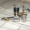
A premilled kit by Bengs
| Howi | 15/02/2016 11:15:29 |
 442 forum posts 19 photos | Brian, you need to approach testing methodically, Â looking at the plans you have shown shows the air inlet to the power piston is at the end furthest from the flywheel, my previous post needs the action of the piston reversing in that case. The opposite end of the power cylinder needs an opening the the atmosphere otherwise you are wasting power compressing air, this air needs to go somewhere.. Another thing you could try is, remove the power cylinder end cover ( one furthest from the flywheel, then spin the flywheel. It looks a fairly hefty flywheel so kinetic energy should keep it turning more than 6 times. You could also disconnect the power piston Conrad and the displacer Conrad and push and pull by hand how do they feel, rough/smooth? Testing needs to be methodical and carefully worked out gradually adding more parts of the linkages until you have everything connected as it should be. The poke and hope method rarely works. Usually the blindingly obvious suddenly smacks you across the face with a wet fish. The "Ah! Bisto" moment. |
| Andy Holdaway | 15/02/2016 11:16:03 |
 167 forum posts 15 photos | Brian, I think you're probably on the right track with the rear cylinder cover. I have left my engine on the shelf for the past few weeks, but decided to have another go at it yesterday. As Howi has suggested, I can blow and suck with abandon and move the power piston. However, I have some leakage around the displacement piston rod. This was reamed M3H7 and is pretty snug, but I still get air past it. I'm sure my problems are down to machining tolerances (inaccuracies) caused by me, but the engine has served it's purpose in getting me used to my lathe. There are a few videos on You tube showing running engines, so the design obviously works. One day I probably re-make all the key parts, hopefully more accurately, and try again. Until then it's an ornament! Andy |
| Howi | 15/02/2016 12:41:47 |
442 forum posts 19 photos | Andrew, a little leakage is inevitable, a little drop of light oil should deal with that. The next thing to consider is timing, get this wrong and you are on a hiding to nothing. Turn the engine over by hand, with the displacer piston furthest away from the heat source, the heat is being applied to the greatest volume of air which is going to increase the air pressure ( as the volume is fixed) and so push the piston towards the flywheel ( power push stroke)ÂÂ . keep turning the flywheel, the displacer piston should now go towards the hot end and push the (now) hot air to the cold end where it will loose heat rapidly, causing negative pressure at the power piston thereby sucking the piston back to the top of the cylinder, (second power stroke),ÂÂ the cycle then Repeating itself. If this is not happening in the right sequence you may need to reverse the direction of flywheel rotation. Some Stirling's will work in both directions others will not. General timeing is usually displacer piston 90 degree out of sync with the power piston. I think you are very close to getting it running,ÂÂ Get some oil on all the bearing surfaces, and get the whole thing running via a drill or mill or whatever for 5 minutes at a time and everything will wear into place. Don't forget a striking needs heat, more heat means more power, use a blow torch. If this gets it going then it is only getting it run in that will allow it to run on a spirit burner. Edited By Howi on 15/02/2016 12:42:58 |
| Ian S C | 15/02/2016 12:43:40 |
 7468 forum posts 230 photos | The reason the hole that the displacer rod comes through is so deep is to (a) stablise the displacer, keep it from sagging and touching the inside of the hot cap/test tube. (b)it's long enough to prevent leaks, the pressure is rising and falling fast enough that it cancels out the air flow down the narrow gap between the rod and the hole. Is the hole square? What happens when the con rod is disconnected from the displacer rod, and the rod is rotated, does the displacer turn concentrically, does it touch any where, for example at full stroke? I know oil is frowned on, but unless it's a graphite piston, a drop of low viscosity oil can be just enough to get things going, just try to stay away from CRC/WD-40, it will work for that run, but when you come back in a few weeks, chances are you won't be able to turn the motor, all gummed up, a squirt of brake cleaner cures that problem. Still thinking--------It will work. Ian S C Edited By Ian S C on 15/02/2016 12:51:45 |
| Brian John | 15/02/2016 13:47:20 |
| 1487 forum posts 582 photos | I just performed an interesting experiment : removed D. piston connections to the crank but left D. piston in place at BDC with glass tube over it in the usual operating position. Turning the flywheel by hand, the work piston forced enough air through the system to gradually move the D. piston up to the end of the tube by about 2mm per revolution. So I think all the airways are clear and operating as intended. I am almost finished the single rod/clevis conversion so I will try that first. I am curious to see if it makes any difference. If I have no luck there then I will return to the initial design. |
| Brian John | 16/02/2016 06:46:07 |
| 1487 forum posts 582 photos | I stuffed up my first attempt at the clevis : the M3 thread was not cut square when I tapped it by hand in the vice so I had to make second one. This one was tapped using the lathe to keep it square which was a success. I then redrilled the first clevis to 2.6mm ( correct tap drill is 2.5mm) and retapped it in the lathe with the plug tap and this worked. The thread is now square so I have two clevis. (What is the plural of clevis...clevii ?) I will assembly it tomorrow and work out the correct length for the D. piston connecting rod. I put an M3 thread on the connecting rod today using the lathe and made the thread long enough to take two adjustment nuts. Almost there !
Edited By Brian John on 16/02/2016 06:46:41 |
| Howi | 16/02/2016 10:39:30 |
442 forum posts 19 photos | Posted by Brian John on 15/02/2016 13:47:20:
I just performed an interesting experiment : removed D. piston connections to the crank but left D. piston in place at BDC with glass tube over it in the usual operating position. Turning the flywheel by hand, the work piston forced enough air through the system to gradually move the D. piston up to the end of the tube by about 2mm per revolution. So I think all the airways are clear and operating as intended. If that is the case there is something seriously wrong somewhere. There should be a sufficiently large gap around the D piston to allow air to flow freely around it. Air being forced back towards the D piston should flow round it NOT push it up the glass cylinder. The D piston ONLY moves air within the glass cylinder, it does NOT provide any means of supplying force to the power piston, that force is supplied by the increase and decrease in pressure of the air in the system due to repeated heating and cooling of the air by the action of the D piston( Boyles law) Â |
| Ian S C | 16/02/2016 10:53:10 |
7468 forum posts 230 photos | I can see one major problem with that last set up, the pivot point is too close to the crank to fit a working con rod, the pivot point has o be the same as the original. You mentioned how the displacer move when it was disconnected, and the piston was moved. This is the basis of the Ringbom motor, in this motor the displacer is not connected to the crankshaft, the only thing that is different is that the displacer rod is quite a bit larger, up to about 1/3 the bore of the displacer cylinder, I'v built three of this type, not over powerful, but they will run in either direction. Ian S C |
| Brian John | 16/02/2016 12:02:34 |
| 1487 forum posts 582 photos | Howi : that experiment was with the largest diameter piston (12.9mm). I have made three of various diameters. The correct diameter is 12.5mm. It was only an experiment to test for air leaks. I am sorry that I did not explain that better. Ian : Yes, I see what you mean. I am using the same connecting rod from the original design. The clevis is too long and there is no room to fit a shorter one. I think I will have to remake part 24 (D.cylinder cover). I really think this is the main problem. I have run out of other ideas ! |
| Ajohnw | 16/02/2016 13:29:57 |
| 3631 forum posts 160 photos | Your problems might just be a bit of binding due to things not lining up Brian. That sort of thing showed up when you ordered new ball races. For those to work as they should the pockets they fit into need to be perfectly axially aligned and square to each other. Same with the con rods. In that case the holes in each end need to be on the same axis, same distance apart when there is 2 on the same journal and their sides need to be square to the holes too. This sort of thing is why asked if your drill table was square to the drill earlier. Few are worse luck. Usually it's possible to square them up one way and the other may need some thought as to how the work is set in a vice and it can be impossible to do that. If this is one of the problems the easiest solution would be to easy the holes a bit and if possible ensure that the holes in the 2 are the same diameter and the same distance apart. This sort of problem has cropped up in some model engineer mag projects in the past and if extreme they have suggested drilling in the lathe. There are 3 ways of doing that. One is holding them on the face plate but that needs the face plate balancing. That's not too bad on small light things as one clamp will hold the work and another can be fitted just to balance things. The other is a drilling plate in the tailstock. I've been looking for one for years. All that can be bought is cross drilling jigs and they are too small to hold things down on. They aren't much good for cross drilling either really, no clamp and the V is usually too small. The other way is some sort of holder in the tool post. It can be fly cut from the chuck to get it square on. I have done this at times using a lash up to allow me to jig bore pretty accurately using the cross slide. The other aspect which you probably have thought of is to make matching parts in one go. Take the double con rod. Drill ream one end of each, fit a tight fitting dowel and then do the other ends together. If these are the problem you might cure it by simply relieving the holes a bit. If I used any oil on these things I would get hold of some watch or clock oil but it can't be used on any really hot bits. That long hole on the displacer shaft is a good idea. The way to view the length of holes like this is how many diameters of the shaft they carry long are they. More diameters means less tip for the same amount of clearance. If say they are 1 dia long rather than say 3 there will be something more akin to point contact at each end of the hole which in practice is likely to cause more friction in a case like this. Too much clearance will have a similar effect. John - |
| Brian John | 16/02/2016 13:53:07 |
| 1487 forum posts 582 photos | I have reassembled the engine as per the original design but with only ONE con rod (the outside one). If I can get this to work with one con rod then I will add the other con rod later. But there is friction there somewhere even with only one con rod. It is late at night now so I will be having a close look at everything tomorrow.
|
| Brian John | 17/02/2016 06:55:06 |
| 1487 forum posts 582 photos | Very frustrating : I have pulled everything apart, polished many parts with 2000 grit wet and dry and then reassembled the engine with only one con rod. I have oiled all moving parts despite the advice to the contrary as I am running out of options. I am not happy with the supplied bearings but the replacements bearings have not arrived from Hong Kong yet so I will have to stick with what I have. Things are running much better now. I am getting 8 revolutions when spinning it by hand with everything connected (one con rod on the D Piston). When the burner is applied I am getting about 16 revolutions. I am sure it is not my imagination 1. It is very hot here today, especially inside the house (about 40 degrees C). The work cylinder gets hot very quickly ; there cannot be too much of a temperature difference between the two cylinders. I might try again later tonight when the air con is on. 2. The supplied bearings are not up to scratch. You might remember that I have put shims between the bearing supports and the covers to stop the bearings being crushed out of shape. It could be that before I inserted the shims that I damaged these bearings when tightening things up the first time. Nothing to do here but wait for the new ones to arrive.
Edited By Brian John on 17/02/2016 06:58:05 Edited By Brian John on 17/02/2016 07:00:42 Edited By Brian John on 17/02/2016 07:10:33 |
| pgk pgk | 17/02/2016 07:14:05 |
| 2661 forum posts 294 photos | Apply soapy water to all the junctions? Seal leaks with silicone. If you have a dremel type tool then use the rubber mandrel in the kit agaist the flywheel to spin it up for a while? Ice the cold side? Pull the bearng shields off and flush out the grease, leave open? Sounds like you're close. Edited By pgk pgk on 17/02/2016 07:14:54 |
| Danny M2Z | 17/02/2016 07:58:31 |
 963 forum posts 2 photos | Brian, you shall get it running eventually. Lol, 432 Posts and 28,192 views - the whole world is waiting with bated breath. Now you are at the stage of eliminating the niggles by focusing on the details I reckon that you have learned heaps about your lathe (which was your aim) so quite a worthwhile exercise. There will be applause all round when the little machine runs on it's own and once you have built one, the next one should become easier. I suspect that they could become quite addictive (Ian SC in NZ seems to be quite fond of the little beasties). Party time in Cairns is close! Regards * Danny M *
|
| Brian John | 17/02/2016 08:19:23 |
| 1487 forum posts 582 photos | Perhaps a cork gasket between the work cylinder and the cylinder holders (frames) ? This might stop a lot of the heat being transferred from the D cylinder to the work cylinder. We will see what happens tonight after the air con has been running for a few hours. A gasket on the D cylinder would also minimise heat transfer to the other side. There are still many things to try yet. Edited By Brian John on 17/02/2016 08:46:28 Edited By Brian John on 17/02/2016 08:47:14 |
| Ajohnw | 17/02/2016 10:22:30 |
| 3631 forum posts 160 photos | I was laying on a bit thick with the alignment of things Brian. It all comes down to clearance between them to some extent but there will be limits on that too. The alignment needs to be better than the clearance otherwise there wont be any. The problem with ball races is that they have virtually no clearance between the running parts. The size of the hole this sort of size goes in is likely to need to be correct to very few 1/10 thou and also round to an even tighter tolerance. Your best bet may have been to bore or ream them together with the caps on and us a tiny speck of super glue in each half. Or nyloc type retaining fluid. Not sure where you are putting the flame. I'd suggest small and not too far from the end. The power cylinder shouldn't be getting too hot to touch. The other aspect is adjustment. As I'm thinking of making one looking around suggest the displacer at it max stroke should go right down the tube to a point where the end clearance is more or less the same as the clearance around it's side. If the clearance is too small it wont work. The power cylinder isn't so simple. That seems relates to the compression ratio of the engine and the ones I have been looking at are all low temperature so that is extremely low. In your case you can probably vary it by say starting with the piston reaching the end of it's cylinder and the reducing the ratio by moving it back. Further back will reduce the compression ratio which in turn "should" reduce the temperature differential needed for it to run. I doubt if that aspect is as precise as the academics reckon but generally it seems to be correct. Leaks seem to be bad news too and the pressure goes up when the things are heated. Adding a bit on that. The engine is likely to run a bit roughly until that settles down. It looks like there are 3 pedestals on each side of the brass plate. Try just using the outer 2 on one side and the central one on the other. 3 point suspension shouldn't distort the plate. The way to make equal length pedestals is with a back stop in the spindle to finalise the length or by using the compound slide for sizing. Face the end with a parting tool and then cut to length. Or the saddle feed if the lathe has one as per myford. John - Edited By Ajohnw on 17/02/2016 10:24:01 Edited By Ajohnw on 17/02/2016 10:25:21 |
| Ian S C | 17/02/2016 11:01:40 |
7468 forum posts 230 photos | John, Loctite (nyloc, type of self locking nut), retaining fluid, screw / nut lock Brian on my first motor I found that I had to loosen the nuts holding the caps on the bearings to get them to run properly. I for got about the front bearing on the displacer rod, I wonder about that, is it dead in line? I would hope it's not too tight. It's a idea I have thought of, but never used (yet). On hot air engines compression ratios are not looked at the same as an IC motor, if the power piston stops at .5 mm from the head, or 5 mm from the head, it will make very little difference in the running of the motor, so the main thing is, it will work as long as the piston doesn't hit the end. Ian S C |
| Brian John | 17/02/2016 11:21:30 |
| 1487 forum posts 582 photos | Thanks Ian : I will not worry about adjusting the work piston then. It would be a waste of time. I have been thinking of making some brass bushes (10mm OD, 6mm ID) to use instead of the ball bearings. My gut feeling is that the bearings are the problem. While I think about that I will try some slightly larger diameter and slightly small diameter D. pistons. I already have them made up so I may as well try them...nothing else is working. NOTE : the air con did not help !
Edited By Brian John on 17/02/2016 11:22:10 |
| Howi | 17/02/2016 11:55:23 |
442 forum posts 19 photos | Brian as has been said, the power cylinder should NOT be getting hot. All that finned brass should be able to dissipate the small heat transfer from the air in the displacer. This needs investigating. Keep the heat applied to the very end of the glass tube, as it is borosilcate it will not transfer much heat through itself to the brass parts. These look to be quite substantial items so should not even feel warm let alone hot. |
| Ajohnw | 17/02/2016 11:58:20 |
| 3631 forum posts 160 photos | The compression ratio of a stirling engine Ian is the ratio of the enclosed volume with the power piston at each end of it's stroke. And yes it does matter but pass on how much. Actually - it matter rather a lot on the very low temperature differential types. John - Edited By Ajohnw on 17/02/2016 12:00:13 |

 It really wants to run but something is stopping it. Possible solutions are :
Please login to post a reply.
Magazine Locator
Want the latest issue of Model Engineer or Model Engineers' Workshop? Use our magazine locator links to find your nearest stockist!
Sign up to our Newsletter
Sign up to our newsletter and get a free digital issue.
You can unsubscribe at anytime. View our privacy policy at www.mortons.co.uk/privacy
Latest Forum Posts
- hemingway ball turner
04/07/2025 14:40:26 - *Oct 2023: FORUM MIGRATION TIMELINE*
05/10/2023 07:57:11 - Making ER11 collet chuck
05/10/2023 07:56:24 - What did you do today? 2023
05/10/2023 07:25:01 - Orrery
05/10/2023 06:00:41 - Wera hand-tools
05/10/2023 05:47:07 - New member
05/10/2023 04:40:11 - Problems with external pot on at1 vfd
05/10/2023 00:06:32 - Drain plug
04/10/2023 23:36:17 - digi phase converter for 10 machines.....
04/10/2023 23:13:48 - More Latest Posts...
- View All Topics
Support Our Partners


Shopping Partners
Subscription Offer

Latest "For Sale" Ads
- Reeves** - Rebuilt Royal Scot by Martin Evans
by John Broughton
£300.00 - BRITANNIA 5" GAUGE James Perrier
by Jon Seabright 1
£2,500.00 - Drill Grinder - for restoration
by Nigel Graham 2
£0.00 - WARCO WM18 MILLING MACHINE
by Alex Chudley
£1,200.00 - MYFORD SUPER 7 LATHE
by Alex Chudley
£2,000.00 - More "For Sale" Ads...
Latest "Wanted" Ads
- D1-3 backplate
by Michael Horley
Price Not Specified - fixed steady for a Colchester bantam mark1 800
by George Jervis
Price Not Specified - lbsc pansy
by JACK SIDEBOTHAM
Price Not Specified - Pratt Burnerd multifit chuck key.
by Tim Riome
Price Not Specified - BANDSAW BLADE WELDER
by HUGH
Price Not Specified - More "Wanted" Ads...
Get In Touch!
Do you want to contact the Model Engineer and Model Engineers' Workshop team?
You can contact us by phone, mail or email about the magazines including becoming a contributor, submitting reader's letters or making queries about articles. You can also get in touch about this website, advertising or other general issues.
Click THIS LINK for full contact details.
For subscription issues please see THIS LINK.
Digital Back Issues


Donate

 Register
 Log-in
Model Engineer Magazine
- Percival Marshall
- M.E. History
- LittleLEC
- M.E. Clock

ME Workshop
- An Adcock
- & Shipley
- Horizontal
- Mill

Subscribe Now
- Great savings
- Delivered to your door

Pre-order your copy!
- Delivered to your doorstep!
- Free UK delivery!
All Forum Topics > Stationary engines > Stirling Engine : Laura