Forum sponsored by:

Mashstroy C210T / Warco 220 help please
| Ivy | 10/02/2012 15:53:40 |
| 77 forum posts 1 photos | I am watching this with great interest. I hope Roger does upload some pictures as well as Peter because my lathe is earlier still, #089 1992 year of manufacture. Ivy. |
| Roger Mountain | 10/02/2012 17:35:17 |
| 14 forum posts 8 photos | 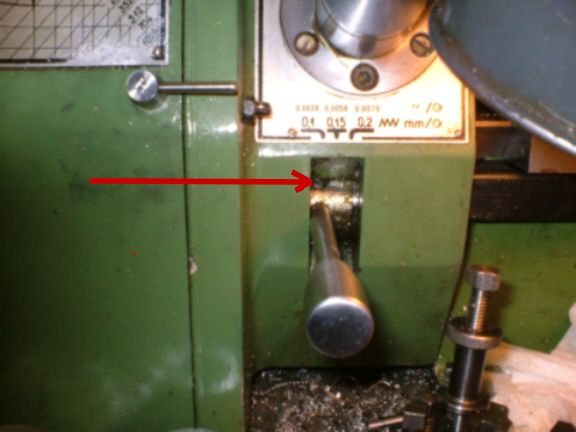 Hi Peter, I have photographed the screw in question you can just see it starting to emerge with 0.1mm/rev feed engaged. Sorry I can't get a better picture but I would have to remove one of the friction wheels in order to get the feed lever to drop down further. Incidentaly with the feed lever pushed down in this position the the auto feed is fully engaged and shows no tendency to jump out. Hope this is some use to you. Regards, Roger PS It looks like there are quite a few differences between these machines. |
| Ivy | 10/02/2012 19:07:30 |
| 77 forum posts 1 photos | As a matter of interest my adjuster screw and lever are arranged the same as Rogers picture but after looking at the manual they are the other way around in the diagram, i.e. adjuster screw below the lever. Yours confused, Ivy. |
| Peter G. Shaw | 10/02/2012 19:30:34 |
 1531 forum posts 44 photos | Ivy, I'm not surprised you are confused! I'm somewhat struggling and I've had mine in bits, and I do mean in bits. Read on... 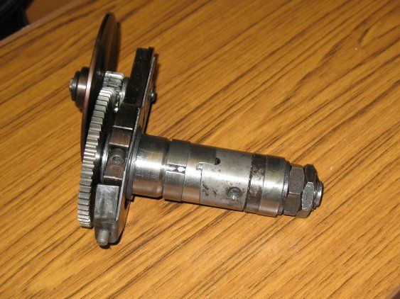 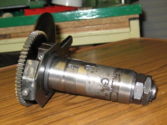 Ok, two photos of the mechanism removed from the lathe. I'll describe later how to get it out, but note if you will, the screw hole where the handle or lever fits. Now, how does this work? Ok, the manual uses all sorts of convoluted phrasing, so here is my version: First of all, the gear wheel (64T, 61T can't remember) on the left is bolted to a shaft which runs through the centre of what you can see here. The leadscrew fits into the shaft at the righthand end with a key. As the mechanism is moved left to right, then the internal shaft slides on the key. The internal shaft fairly obviously rotates inside the mechanism. That's all there is to say about the shaft. Right, the mechanism proper. If you look carefully, and I don't know how much the picture can be expanded before it becomes unreadable, but you will notice that towards the left hand side can be seen part of a cone. Adjacent to it and to the right is the matching internal split cone. Actually, there are other photos below which possibly shows it more clearly. Next to the internal cone is a greyish looking piece in which the handle is screwed. This part can rotate - you can see ball bearings to it's right. Also to it's right are another pair of cones. Now the grey part also is cut at an angle - might just be visible above. Rotation of the grey part, forces the two pairs of cones together whereupon the two split parts are forced to expand and in turn grip the inside of the headstock housing. To continue, having just saved it! The two large nuts are used to adjust the mechanism slackness, if that makes sense. What you do is tighten up the thicker nut, and then lock it with the thinner nut. And don't let's get bogged down in the argument of which way round the nuts should be - this is how Mashstroy have set it up. 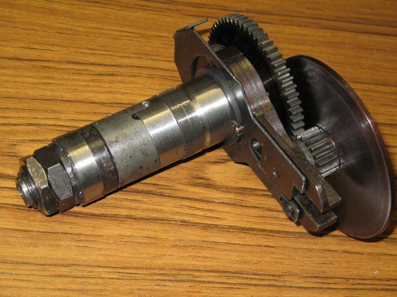 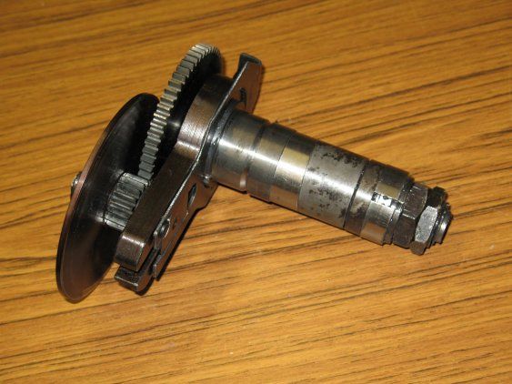 These two photos are simply different views. The last one is with the mechanism upside down to allow a photo of the underneath - not that there is anything of note! Just done another save. 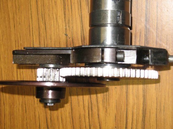 This photo is just the external part of it, but it does show the fixed external cone and the split cone - with a short key. Ok, I've just been told the post is too long. So the remainder will follow below. Regards, Peter G. Shaw Edited By Peter G. Shaw on 10/02/2012 19:58:38 |
| Peter G. Shaw | 10/02/2012 19:59:06 |
1531 forum posts 44 photos | Continued from above. Last bit - how to get it out in one piece. Obviously this only applies to my style of lathe. If yours is different, then this may not work. Ok, here goes. First stick your fingers onto the leadscrew, ie under the leadscrew guard. Rotate the leadscrew using the handwheel until you can feel the longitudinal slot in the leadscrew. Now turn the leadscrew using the handwheel until the slot is at the top. (If you do not, then there is a chance you will drop the key out, but do not worry, there is an easy work around that one. How do I know? Don't ask !!!) Now remove the handle - it is just a normal right hand thread - having made sure that it is in its uppermost position. Once it is removed, open the gearbox cover and pull out whatever is there, (gears if screwcutting, or turning wheels) along with the mechanism. Having got it out, look down the righthand end and you should see the sliding keyway I mentioned above. Look through the big hole on the headstock casting, and with luck you should see the end of the leadscrew with the key still located and uppermost. To reassemble, insert the mechanism ensuring that the sliding keyway is at the top and simply feel it into engagement with the leadscrew. Easy-peasy. Well, I think it is easy, but then I have had it out a number of times. It might be difficult if anything such as the large disk starts catching on say the pulleys, or the spring loaded thingy middle front decides to be awkward. Or even if the expandable spring rings are expanded too much. But I did not have any trouble at all. Ok, you've rotated the leadscrew down and the key has dropped out. Now I have small short fingers and although I can get them in, they are not long enough or thin enough to replace the key. So, here is what to do. At the other end of the leadscrew, undo and remove the adjuster, two screws to slacken, then screw it off. Remove, leave in place, whatever, the thrust bearing - it will most probably drop off whatever you do. Now slide the leadscrew, saddle and everything else towards the left until the end of the leadscrew becomes visible. Now you can replace the key. I actually found that I could replace the key through the gap where the handle fits. Carefully rotate the leadscrew so that the keyway plus key are at the top, slide the whole job lot back to the right, replace the thrust bearing (you did take note of the order of the parts didn't you), replace the adjuster, adjust as necessary, lock up and Bob's your Uncle. It might actually be a good idea to replace the mechanism before adjusting, not because it will have any effect on the adjustment, but more to prevent the key dropping ut if you accidently rotate the leadscrew again. Ok folks, that's all! Any problems? No? Good! Regards, Peter G. Shaw Edited By Peter G. Shaw on 10/02/2012 19:35:36 Edited By Peter G. Shaw on 10/02/2012 20:03:47 |
| Peter G. Shaw | 10/02/2012 20:14:05 |
1531 forum posts 44 photos | Roger, I ain't not got your screw. Just a thought. Maybe my operating procedure is different to yours. Here is mine. To engage a fine feed, I select the speed by moving the lever sideways to the appropriate position. I suspect that is the same for you. Next, I press down the lever until the wheels engage. Now, I have to press even further, and harder. What this does, is that it uses the resistance to further movement generated by the engagement of the wheels to lock the left hand side of the mechanism in place (see posts above). Further movement down of the lever now causes the cones to move together thus forcing the split cones (known as cut rings in the manual) to spring and expand thus gripping the inside of the headstock. It seems that when using 0.1mm the pressure generated is not sufficient to force the wheels to grip. When screwcutting, all is ok except that when reversing, there is a tendency for the gears to jump out of engagement, presumably because the action of the gears is such as to help the mechanism to move out of engagement. Needless to say, I know hold the lever in gear to make sure. Also Roger, can you describe the type of gib adjustment you have. Is it normal gib strips, a few mm thick? Or is a ginormous CI block that has to be moved around and then clamped back in position? The reason I ask is that I have this ginormous ci block and it's not easy to adjust. Effectively I have to slacken the three clamp bolts, adjust two adjusting screws hopefully correctly, and then tighten the three clamp bolts and try it. If it still is not right, repeat the above. Unfortunately, because the cast iron block is so stiff, and there are only two adjusting screws, the two screws do intereact such that tightening one up affects the adjustment of the other. Whereas with normal gib strips one can get it right first time. Regards, Peter G. Shaw Edited By Peter G. Shaw on 10/02/2012 20:26:43 |
| Ivy | 10/02/2012 20:34:49 |
| 77 forum posts 1 photos | Peter, I appreciate all of the trouble you went to for that picture essay, it certainly will help me or at make it easier to understand when I get stuck into mine. Thanks again, Ivy. |
| Peter G. Shaw | 10/02/2012 21:27:51 |
1531 forum posts 44 photos | Ivy, Believe it or not, the biggest problem was the actual write up - and even then it was really quite easy. The photos I have now got off to a fine art - get out the digital camera, run off a few shots, upload to the computer, use PaintShop Pro to reduce the size, upload to site, job done.The dismantling also is dead easy, mainly because I've done it all before. So, as I think the Aussies say, " no worries mate". Anyway, come back if you want more. Use the private messaging system if you want. It really does not take long to take a few photos and write a description. Regards, and good night - it's my beddy-bies time now. (Actually it's prepare for bed, and then start reading!) Cheers, Peter G. Shaw |
| Bazyle | 11/02/2012 11:37:36 |
 6956 forum posts 229 photos | Thanks for the details and photos. It is interesting to see if such a mechanism has possibilities elsewhere.
I take it that the friction disc engages with a stepped wheel with 3 different diameters for the feeds and there is some spring to ensure friction, and that is one aspect that needs adjustment from the screw menioned in an early post.
Then the first part of the locking process is to lock the sideways position and then prevent rotation that would reduce the pressure from the aforementioned spring.
It looks like a simple sheet metal catch pivoted on a screw in the casing could be arranged to hold down the lever and by having a sloping engagement face it would be able to apply whatever force was needed. I would put it just to the right so it could be pushed over by thumb as the lever is engaged. |
| Peter G. Shaw | 11/02/2012 14:00:08 |
1531 forum posts 44 photos | Bazyle, Yes, the large friction disc does indeed engage with a stepped wheel with three different diameters, each of which has a flange at each side thus ensuring that the disc engages correctly. There is no actual physical spring, other than one used to help locate the mechanism positively sideways. If you look at my second and third photos you will see a thin sliding plate with a bit bent over and a rod sticking out at the front. This rod slides over a triple grooved rod to provide the location information. The plate itself slides back & forth and disengages the friction disc and associated little gear wheel from the large gearwheel in the fully disengaged position. From what I can see of the mechanism, all the pressure to ensure drive between the friction wheel and the three stepped wheel comes from the hand lever mechanism. I suspect that the combination of low gearing plus the effort required to shift the carriage is borderline for the drive. Certainly in the two higher speeds, it is nowhere near as bad and let's face it, the effort required to shift the carriage will be the same. As I have written this, I have realised that this does not make sense so I will have to have another look at as theoretically, it should work best at lowest speed: a bit like a car with a slipping clutch which will work ok in 1st or 2nd, but slip in 5th & 4th. The idea of a sheet metal catch is something I had idly thought about, but as it wasn't really a problem I never bothered pursuing. In any event, I have a suspicion that the positioning of the lever varies according to the stepped wheel postioning and gear cutting. More to look at. I'll take another photo to show the external visible mechanism. Watch this space. Regards, peter G. Shaw |
| Peter G. Shaw | 11/02/2012 14:57:17 |
1531 forum posts 44 photos | As promised two more photos showing the visible mechanism. 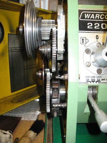 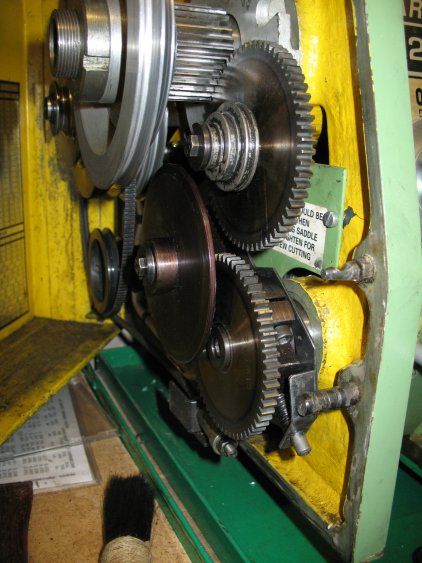 You will be able to see the disc and the three-step pulley. Also, in the first photo, you can just see the small attached gear wheel which meshes with the large one at the front. Also on both photos can be seen the triple grooved rod which acts to locate the sideways positioning, and the spring loaded mechanism which locks it in place (lower photo). I was right in that the positioning of the operating lever, visible in the top photo, does vary in it's position when engaged. Which means that any latch to hold it down will have to spring loaded. Indeed, I think it would have to be quite a hefty spring to be of any use. I would still like to know more about Roger's machine, eg what does the pad bear on to stiffen things up? Does his machine still use the split cones? Presumably the adjustment screw and pad are through the circular part that the handle screws into. Regards, Peter G. Shaw |
| Nicholas Farr | 11/02/2012 18:36:48 |
 3988 forum posts 1799 photos | Hi all, further to my previous post and inspired by Peter's photos and various comments by everyone, I've had another look at my lathe and studied the pink C210T manual. The operation and explanation of the feed mechanism is not detailed in the Warco manual in so much depth as it is in the pink one. Like Peter I have in the past had this mechanism out, and yes as Peter says keep the leadscrew key and keyway at the top, as it is a very fiddlely job to put the key back into place.
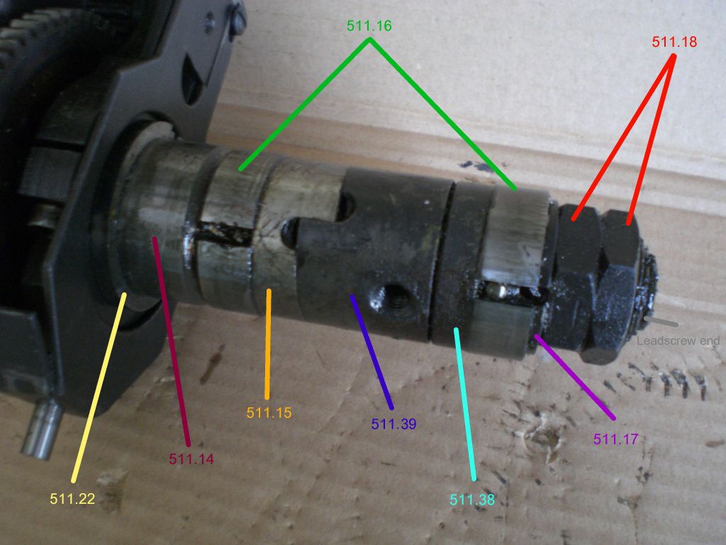
I have now found that it is possible to lock the feed lever down and there is no need to hold it, but it takes a little extra effort on the lever to do so. I think Peter's explanation more or less says it all as to how it all works, so today I studied the pink manual pages E14 and E19 sub tittled The feed mechanism and in conjunction with fig 6 on page E16 and at the same time taking mine out and studying it on the bench. Below is a photo of mine which I've labeled with the numbers in the text showing which bits they are talking about.
 This next photo is with the lever turned into the locking position 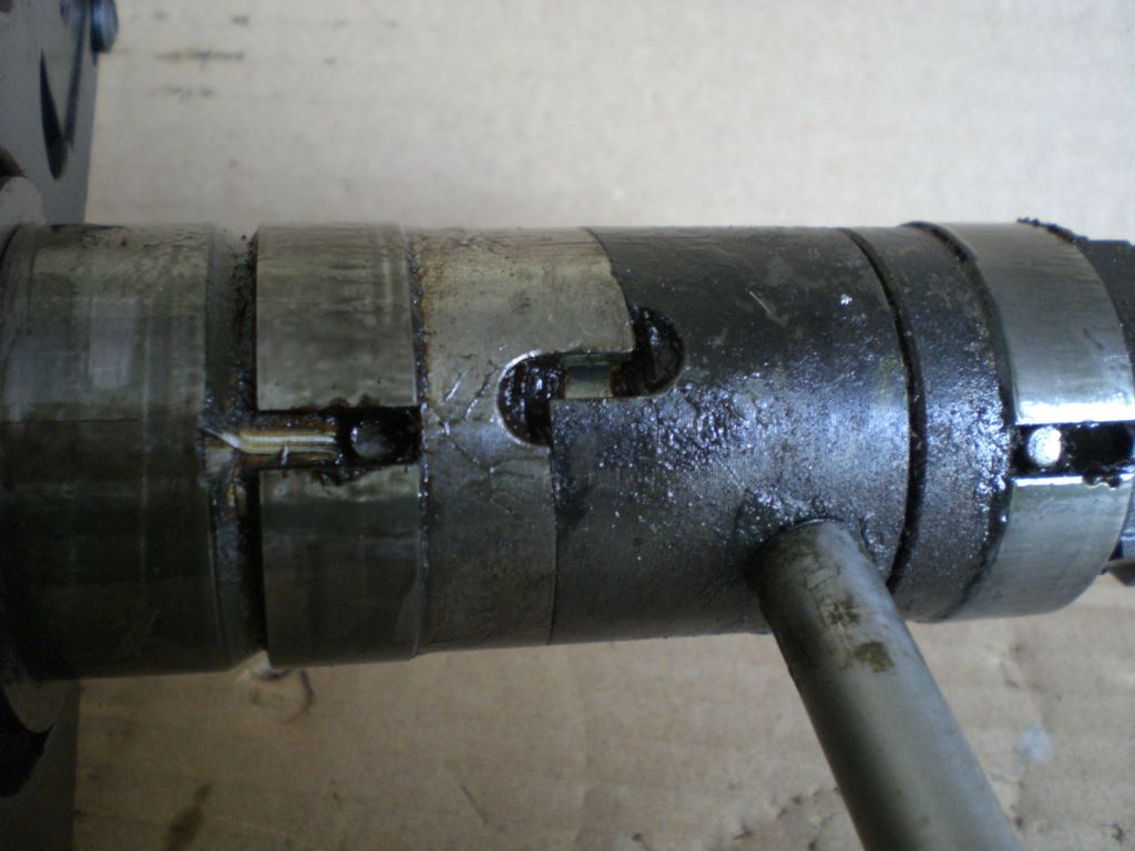 There is another photo in my Warco 220 lathe album which shows inside the housing where this fits, and the end of the leadscrew and the key can be seen. There is also an alternative sectional diagram of the mechanism to that shown on page E16. Like Peter I have not found the screw or pad that Rodger has mentioned.
When the lever is in the locked position, it takes more than a flick to release it, so some times it may be easyer just to hold it down when using on a short distance up to a shoulder for instance.
Hope this is of some more help to everyone.
Regards Nick. Edited By Nicholas Farr on 11/02/2012 18:38:14 |
| Peter G. Shaw | 11/02/2012 21:44:44 |
1531 forum posts 44 photos | Hi Nick, Firstly, congratulations on your photos: they are much clearer than mine. Secondly, I'm interested in two of your comments: "I have now found that it is possible to lock the feed lever down and there is no need to hold it, but it takes a little extra effort on the lever to do so." and: "When the lever is in the locked position, it takes more than a flick to release it," What this is saying to me is that maybe my adjustment of the two nuts, 511.18, is not tight enough, hence the expanding cones are not expanding sufficiently to grip the inside of the housing properly thus allowing everything to disengage by itself. Maybe I'll try tightening it up some more. Regards, Peter |
| Roger Mountain | 11/02/2012 22:27:23 |
| 14 forum posts 8 photos | Hi Folks, Sorry I have been so long in replying but I have been unsuccessfully battling a front door lock. Many thanks to Peter for his excellent desription of the workings of the auto feed and the accompanying photos. Yes I have had the auto feed out of my lathe and as I recall it was the same as Peter's apart from the extra grub screw (yes I did lose the key from the lead screw, the parts gremlin shot out from under the bench and made off with it, only returning it after I had filed up a new one from silver steel). The grub screw is threaded into the same cylindrical component as the feed lever it is also shown in the pink manual but the feed lever and the grub screw are transposed. Yes Peter I do have the same gib strips as you, they can be a pain to adjust but once done they don't seem to need touching for ages. I have drilled and tapped mine M6 in order to accomodate slide locks. 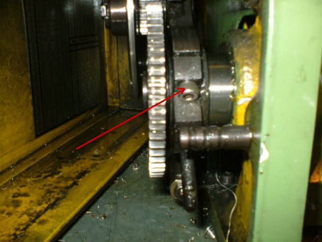 As regards jumping out of gear whilst screwcutting this can be avoided by tightening the screw indicated in the above photo, I don't bother as my lathe has never had this tendency. In order to better lubricate the saddle I have drilled and tapped the front of the saddle for a countersunk M6 screw, this is removed for a few squirts of machine oil every now & again. Just a tip for you Ivy make yourself a wooden bed protector so that when you drop the heavy 4 jaw chuck you don't mark the bed. Hope this has been of some use, Regards, Roger |
| Nicholas Farr | 11/02/2012 23:40:53 |
3988 forum posts 1799 photos | Hi Peter, thanks for the appreciation of my photo's, but I think yours a equally as clear as mine, but with my compact Casio Exilim, I can get close shots. It could be that there is too much slack in your mechanism, in the pink manual it says the adjustment should be that the cut rings 511.16 should touch the faces of the nut 511.15 without any play. In the second photo of mine showing it in the locked position, that is as far as I could turn it whilst out of the lathe by holding the fork 511.11 in one hand and the lever in the other and it stayed there without any indication of it slipping back on its own. It was your photos that prompted me to take a more detailed look, so please don't do yourself down on them, every picture tells a story and helps others. I labeled my first photo for my own benifit as much as anything else to help me understand the text in the pink manual.
Roger, I guess your grub screw must be that which is in the detail on page E17, this seems to have no relevance to my lathe.
Regards Nick. Edited By Nicholas Farr on 11/02/2012 23:46:08 |
| Peter G. Shaw | 12/02/2012 11:33:54 |
1531 forum posts 44 photos | Roger & Nick, 1. My camera is a Canon Powershot A640. Unfortunately, I am/was too lazy to use the tripod. It does have a macro setting, but as yet, I haven't really worked out the best way to use it. So, my photos tend to be handheld, normal focussing on auto, zoomed in as necessary amd usually with the "unsteady" light flashing away merrily. This is why there is a little bit of blurring on my photos. 2. My page E17 is all text. Page E16 does have some diagrams on it, but nothing that I could reasonably consider to be a grub screw. Here's a photo (macro setting & tripod would you believe) of the relevant part of page E16. 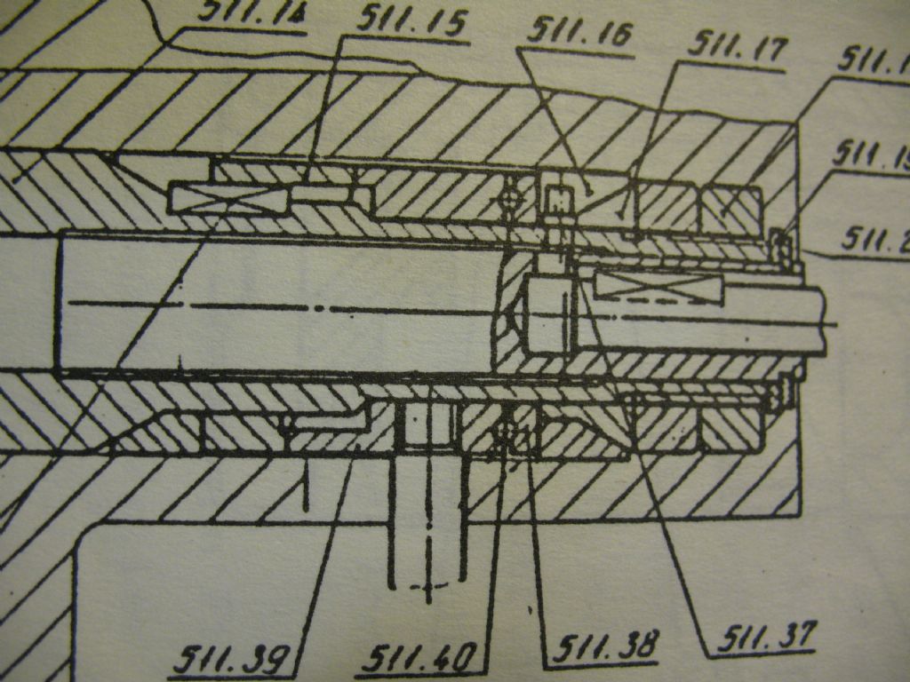 This is the only drawing that I have got for this mechanism and does match what exists physically. Final comment re photos. In answer to Roger, I did say that I was uploading at 3Kb. This particular photo was uploaded at 3Mb. I haven't checked, but I assume the site must reduce the size to suit. Edit: In fact the site says that the photo is 128.71Kb, 1024 x 768 pixels & reduced to 350 x 263 pixels. The uploaded original was 2816 x 2112 pixels. So some serious reduction there. Regards, Peter Edited By Peter G. Shaw on 12/02/2012 11:37:05 |
| Ivy | 12/02/2012 11:42:54 |
| 77 forum posts 1 photos | Post deleted. Sorry my attempts at posting pictures was a dismal failure. Edited By Ivy on 12/02/2012 11:49:58 |
| Les Jones 1 | 12/02/2012 12:22:43 |
| 2292 forum posts 159 photos | Hi Ivy, Have a look at the "Wind up torch" thread. There is advice on posting pictures near the end of that thread. Les. |
| Peter G. Shaw | 12/02/2012 13:00:31 |
1531 forum posts 44 photos | Ivy, Here's my take on uploading photos: Take photo. Transfer to computer. (Should be as a jpg. If not, then run it through a photo editing program to convert it.) Login to the ME/MEW website. Go to My Photos. Create a Photo Album. Give it a name. Then go to Upload Photos and use the Browse function to upload an individual photo (or five). Finally select Upload photos. Now make any editorial changes you wish. Finally, go to the thread, eg here, then "Post a reply". Click somewhere in the box and then click onto the icon second from right. This then allows you to select your album and hence your photo. Nick, Realised now that you have additional photos in your album - including an alternative line drawing which is exactly mine. This implies you have another drawing of same. Any chance of a look? Roger, Interested in how you did your slide locks. Did you do it from top to bottom, eg as the three clamp screws? Or did you manage to drill through the this section of the adjustable block? And if so, wouldn't this lead to weakening the block? Thinking now about the screw and pad. Your screw looks to be about 90° round from, and in line with the handle. Correct? Presumably it then bears on the tubular section that everything totates on and has a brass or copper pad between the screw end and this tubular section. Correct? If I'm right, then it should be a very simple modification to do. But I do wonder how new your lathe is, because Ivy seems to imply that she has this adjustment yet her lathe is older than mine. Also, Nick doesn't have it. So could it be that later lathes don't have it, or was just a certain batch that didn't have it? I also use a piece of wood to protect the bed: I find the 160mm chuck rather heavy! Not too sure about the additional lubrication though, I use the feed nipple in the middle of the saddle and everything seems to get pretty well covered using H68 type oil. I have though, added a small oil feed hole in the middle of the bracket which holds the cross-slide leadscrew, the isea being to lubricate the bearing below. Regards, Peter |
| Roger Mountain | 12/02/2012 13:28:15 |
| 14 forum posts 8 photos | Hi Folks, Here is page E17 from my manual Regards, Roger 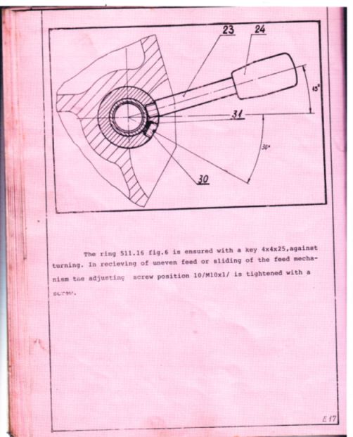 |
Please login to post a reply.
Magazine Locator
Want the latest issue of Model Engineer or Model Engineers' Workshop? Use our magazine locator links to find your nearest stockist!
Sign up to our Newsletter
Sign up to our newsletter and get a free digital issue.
You can unsubscribe at anytime. View our privacy policy at www.mortons.co.uk/privacy
Latest Forum Posts
- hemingway ball turner
04/07/2025 14:40:26 - *Oct 2023: FORUM MIGRATION TIMELINE*
05/10/2023 07:57:11 - Making ER11 collet chuck
05/10/2023 07:56:24 - What did you do today? 2023
05/10/2023 07:25:01 - Orrery
05/10/2023 06:00:41 - Wera hand-tools
05/10/2023 05:47:07 - New member
05/10/2023 04:40:11 - Problems with external pot on at1 vfd
05/10/2023 00:06:32 - Drain plug
04/10/2023 23:36:17 - digi phase converter for 10 machines.....
04/10/2023 23:13:48 - More Latest Posts...
- View All Topics
Support Our Partners


Shopping Partners
Subscription Offer

Latest "For Sale" Ads
- Reeves** - Rebuilt Royal Scot by Martin Evans
by John Broughton
£300.00 - BRITANNIA 5" GAUGE James Perrier
by Jon Seabright 1
£2,500.00 - Drill Grinder - for restoration
by Nigel Graham 2
£0.00 - WARCO WM18 MILLING MACHINE
by Alex Chudley
£1,200.00 - MYFORD SUPER 7 LATHE
by Alex Chudley
£2,000.00 - More "For Sale" Ads...
Latest "Wanted" Ads
- D1-3 backplate
by Michael Horley
Price Not Specified - fixed steady for a Colchester bantam mark1 800
by George Jervis
Price Not Specified - lbsc pansy
by JACK SIDEBOTHAM
Price Not Specified - Pratt Burnerd multifit chuck key.
by Tim Riome
Price Not Specified - BANDSAW BLADE WELDER
by HUGH
Price Not Specified - More "Wanted" Ads...
Get In Touch!
Do you want to contact the Model Engineer and Model Engineers' Workshop team?
You can contact us by phone, mail or email about the magazines including becoming a contributor, submitting reader's letters or making queries about articles. You can also get in touch about this website, advertising or other general issues.
Click THIS LINK for full contact details.
For subscription issues please see THIS LINK.
Digital Back Issues


Donate

 Register
 Log-in
Model Engineer Magazine
- Percival Marshall
- M.E. History
- LittleLEC
- M.E. Clock

ME Workshop
- An Adcock
- & Shipley
- Horizontal
- Mill

Subscribe Now
- Great savings
- Delivered to your door

Pre-order your copy!
- Delivered to your doorstep!
- Free UK delivery!
All Forum Topics > Hints And Tips for model engineers > Mashstroy C210T / Warco 220 help please