Forum sponsored by:

Machining Crankshaft
| Ady1 | 06/02/2012 10:52:43 |
 6137 forum posts 893 photos | The idea of milling away as much as possible has the same advantage as grinding, the cutting loads are less than for turning That does seem to be the best system for hogging out most of the material, the shaper would be more fiddly. The other problem is stiffness between the centres, you need to squash the workpiece between centres, which becomes a big issue as you hog out more material. Perhaps holding the workpiece between two four jaw chucks would be better, certainly it would be less stressful If you only move a single jaw on the 4 jaw when revolving the workpiece for the next offset crankpin, so you reposition the WORKPIECE, and don't move 3 jaws, then you will get...well moderate concentricity The original setup between 4 jaws will need some dial indicator work. I made a revolving centre for my chucks to fit on the tailstock(great for hogging down wonky bars of metal), a smaller one would be more sensible, you can see the general thinking. Thats a three jaw in the tailstock example, obviously I would use a good small 4 jaw...if I could afford one. So with a good quality revolving centre in the tailstock you have stiffness and security, but very little crushing force on the workpiece. Final high accuracy finishing work with light cuts and a carbide quality parting tool can still be done between the centres  2cents Edited By Ady1 on 06/02/2012 11:14:00 |
| Ady1 | 06/02/2012 12:06:52 |
6137 forum posts 893 photos | For positioning the workpiece a centre which protudes only slightly from the middle of the 4 jaw body would make setting and resetting the job miles easier. This photo is obviously not what I mean, each 4 jaw would have a specially made centre where the workpiece could be positioned easily between these centres, and then the 4 jaw chuck jaws secure the workpiece in position Saves messing about checking stuff once the initial work for the holes for the offset centres have been done.  To get the holes set accurately at each end I would do one end, then make a template of the first end, which I would transfer to the other end for marking out. That would be pretty fiddly and need some thought though...The holes at the opposite ends really do need to be spot on. Maybe better men than me could help out here, since these holes are quite critical for accuracy and a good crankshaft Sooo Set your holes up properly hog out most of the material with a small milling cutter finish off with a good parting tool Seems to be the easiest system for an amateur |
| JasonB | 06/02/2012 12:43:08 |
 25215 forum posts 3105 photos 1 articles | Or just clamp one end in a keats angle plate and move that about on your faceplate until the journal is true, this gives support right upto the web and very little overhang.
J |
| Stub Mandrel | 06/02/2012 19:33:41 |
 4318 forum posts 291 photos 1 articles | I've seen Jason's partiing tool before - recommended by LBSC, and I can confirm it works. Neil |
| John Bentley | 06/02/2012 21:59:13 |
 3 forum posts | John (Bridge) didn't actually say that his crankshaft was unusually hard and in fact mentioned that he had already removed the surplus metal at the weld. It wouldn't surprise me if he has finished the job successfully by now.
I have not found the Stuart crankshafts particularly flimsy while turning them normally. They cut very well without distortion in either my Peatol or my Chinese mini lathe. Similar freelance versions (up to three throws) made from solid bar have turned out equally well for me. I didn't have any experience when I started out and haven't had any trouble at all with conventional crankshaft designs like these. Success is probably the result of no more than using sharp tools at proper height with gentle cuts at sensible speed.
Jason's recommendation of LSBC's tool looks like a good one and I will be trying it out next time.
John
|
| JOHN BRIDGE 1 | 06/02/2012 22:13:47 |
| 104 forum posts 11 photos | Posted by John Bentley on 06/02/2012 21:59:13:
John (Bridge) didn't actually say that his crankshaft was unusually hard and in fact mentioned that he had already removed the surplus metal at the weld. It wouldn't surprise me if he has finished the job successfully by now.
I have not found the Stuart crankshafts particularly flimsy while turning them normally. They cut very well without distortion in either my Peatol or my Chinese mini lathe. Similar freelance versions (up to three throws) made from solid bar have turned out equally well for me. I didn't have any experience when I started out and haven't had any trouble at all with conventional crankshaft designs like these. Success is probably the result of no more than using sharp tools at proper height with gentle cuts at sensible speed.
Jason's recommendation of LSBC's tool looks like a good one and I will be trying it out next time.
John
This is correct John it was not unduly hard and I had removed the surplus, I have made a tool similar to the pic. and it is quite easy now to machine this journal it is now quite smooth but is still in the 3 jaw and revolving center in the tailstock there is still plenty of meat on the journal and I now intend to transfer to between centers and finish off this shaft, I am now quite confidant that I can now do the job. Like you I find the shaft quite sturdy and I do not intend to use any stengthening whilst turning.
John
|
| JOHN BRIDGE 1 | 06/02/2012 22:31:23 |
| 104 forum posts 11 photos | JasonB is the total width of that blade 3/32", I would like to give it a try, what sort of grinder do you use to do the fine shaping, my grinder is a clarke 6" which seems a little large for this job.
John |
| JasonB | 07/02/2012 07:52:14 |
25215 forum posts 3105 photos 1 articles | You can either do it with a parting blade like the Eclipse ones which are nice and deep but they lack side clearance so either set them up dead true with a DTI or grind from a HSS blank but where the neck is narrow is a weak point.
Width would depend on the journal width buy I would say something like 1/3 of the total. And as you are only taking a few thou a pass with this tool us ealternate left & right hand tools to do most of the work.
I only have a 6" bench grinder and a clarke belt/disc sander. a diamond stone will help with refining teh profile
I actually took the tool profile from Malcom Frosts (the M of MJ Engineering) traction engine articles no LBSC but guess that is where he got it from.
J |
| KWIL | 09/02/2012 21:06:05 |
| 3681 forum posts 70 photos | Jason has asked me to post this photo of the crank journal tool using round inserts. Setting is straight forward as a ground tool, if it needs sharpening, just rotate the inserts! 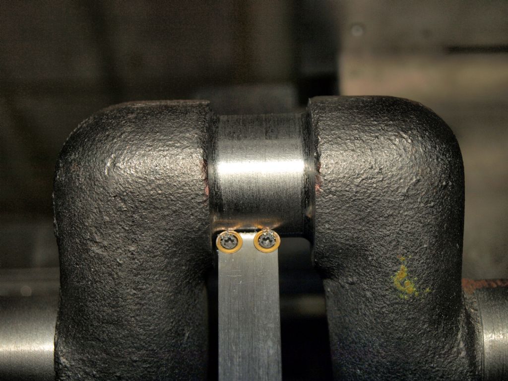 I hope you find it interesting K Edited By KWIL on 09/02/2012 21:06:31 |
| JOHN BRIDGE 1 | 09/02/2012 21:18:01 |
| 104 forum posts 11 photos | Thanks Kwil, It looks like a very useful tool if I ever get to do anything useful with this lathe of mine.
John |
| JasonB | 10/02/2012 18:23:41 |
25215 forum posts 3105 photos 1 articles | I came accross this thread which shows a tool ground like the LBSC shape, may give you a better idea of how its done
J
PS Thanks for adding the photo KWIL. |
| Stub Mandrel | 10/02/2012 21:29:35 |
4318 forum posts 291 photos 1 articles | Wow Kwil, either those are very diddy inserts or that's a meaty crankshaft 3 or 4" Traction engine?  I like the idea of grinding crankshaft journals. A set up using my rotary table on my grinder appeals, but I'd need a different shape wheel. With a diamond wheel a mirror finish could be assured. Neil |
| KWIL | 12/02/2012 10:53:01 |
| 3681 forum posts 70 photos | Neil, They are 5mm diameter and it is a 4" Traction engine, throw is 1.5". The crankshaft was left +0.0005" for grinding/lapping. K |
| Stub Mandrel | 12/02/2012 19:49:34 |
4318 forum posts 291 photos 1 articles | Thanks Kwil, Canme across a Tubal Cain crankshaft turning tool today in his Sirius series. HSS with teh double lobed end, but like your it is parallel, not tapered like a parting tool. Neil |
| Dusty | 12/02/2012 20:59:20 |
| 498 forum posts 9 photos | It has long been known that carbon steel tools can be made with a much keener edge than H.S.S. tools. There is however a downside in that they do not maintain this edge very well, basically they wear, as they wear the the edge is lost and finish and dimensional stability of the workpiece is lost (it gets bigger). This is especially true of mild steel EN3( I would not attempt anything harder) and some of the forged crankshafts we use. If you do use Carbon Steel tools, speed must be reduced and the tool flooded with cutting oil. The other problem with Carbon Steel tools is they can easily loose their hardness when grinding by overheating.
I make my bifurcated tools from parting tool blades and put the groove into the front of the tool with a Dremel/Proxxon and a cut of wheel. |
| JOHN BRIDGE 1 | 12/02/2012 21:08:14 |
| 104 forum posts 11 photos | Dusty, Thanks for this post I was contemplating using a Dremel to cut the groove as I could see no way of doing it with my 6" clarke.
John |
Please login to post a reply.
Magazine Locator
Want the latest issue of Model Engineer or Model Engineers' Workshop? Use our magazine locator links to find your nearest stockist!
Sign up to our Newsletter
Sign up to our newsletter and get a free digital issue.
You can unsubscribe at anytime. View our privacy policy at www.mortons.co.uk/privacy
Latest Forum Posts
- hemingway ball turner
04/07/2025 14:40:26 - *Oct 2023: FORUM MIGRATION TIMELINE*
05/10/2023 07:57:11 - Making ER11 collet chuck
05/10/2023 07:56:24 - What did you do today? 2023
05/10/2023 07:25:01 - Orrery
05/10/2023 06:00:41 - Wera hand-tools
05/10/2023 05:47:07 - New member
05/10/2023 04:40:11 - Problems with external pot on at1 vfd
05/10/2023 00:06:32 - Drain plug
04/10/2023 23:36:17 - digi phase converter for 10 machines.....
04/10/2023 23:13:48 - More Latest Posts...
- View All Topics
Support Our Partners


Shopping Partners
Subscription Offer

Latest "For Sale" Ads
- Reeves** - Rebuilt Royal Scot by Martin Evans
by John Broughton
£300.00 - BRITANNIA 5" GAUGE James Perrier
by Jon Seabright 1
£2,500.00 - Drill Grinder - for restoration
by Nigel Graham 2
£0.00 - WARCO WM18 MILLING MACHINE
by Alex Chudley
£1,200.00 - MYFORD SUPER 7 LATHE
by Alex Chudley
£2,000.00 - More "For Sale" Ads...
Latest "Wanted" Ads
- D1-3 backplate
by Michael Horley
Price Not Specified - fixed steady for a Colchester bantam mark1 800
by George Jervis
Price Not Specified - lbsc pansy
by JACK SIDEBOTHAM
Price Not Specified - Pratt Burnerd multifit chuck key.
by Tim Riome
Price Not Specified - BANDSAW BLADE WELDER
by HUGH
Price Not Specified - More "Wanted" Ads...
Get In Touch!
Do you want to contact the Model Engineer and Model Engineers' Workshop team?
You can contact us by phone, mail or email about the magazines including becoming a contributor, submitting reader's letters or making queries about articles. You can also get in touch about this website, advertising or other general issues.
Click THIS LINK for full contact details.
For subscription issues please see THIS LINK.
Digital Back Issues


Donate

 Register
 Log-in
Model Engineer Magazine
- Percival Marshall
- M.E. History
- LittleLEC
- M.E. Clock

ME Workshop
- An Adcock
- & Shipley
- Horizontal
- Mill

Subscribe Now
- Great savings
- Delivered to your door

Pre-order your copy!
- Delivered to your doorstep!
- Free UK delivery!
All Forum Topics > Beginners questions > Machining Crankshaft