Forum sponsored by:

Stuart 10V
| Steve Rowbotham | 10/09/2023 15:41:24 |
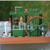
 52 forum posts 30 photos | Hello Scott, sorry I'm a bit late to this thread, only just seen it. To answer your question 'has anyone else come across the 11/16 vs 5/8' issue, the answer is yes I did earlier this year. I am new to Model Engineering, this was my second engine and I had the same dilemma, so I decided to make machine the base casting and bearings and measure the width between the inner faces, and found it to be 11/16 as per the pic below (bit of interpolation needed!). I then made the crank to the 11/16 dimension, it was a tight fit between the bearings and needed a little easing. I would be interested to hear how you got on with this. I finished the 10V a few months ago, and am very please with how it runs (on steam). I have now bought the reversing gear which which I will tackle after my current project, the Stuart Beam which I am currently half way through. Steve
|
| Rick Hann | 10/09/2023 18:39:55 |
| 21 forum posts | Ah! One must first determine what "the job" is! The desired result is a smooth moving piston with minimal friction that seals. To do that you must know what ACTUAL dimensions you are dealing with. I.E. ACTUAL bore diameter, ACTUAL O-ring X-section diameter, and desired O-ring compression I have found that 5% compression is the upper limit of compression. If it were me, I would shoot for a for no more than .005" total compression. For example: Assume a nominal bore diameter of .750". Assume actual bore diameter = .753". Assume nominal 3/4" x 1/16" (.0625"
|
| Scott Murray 1 | 12/09/2023 07:02:19 |
| 10 forum posts | Stuart 10V Hi, Would brass be a suitable material for the piston and valve rods for the Stuart 10V? Scott. |
| JasonB | 12/09/2023 07:33:27 |
 25215 forum posts 3105 photos 1 articles | Probably be lower down the list than mild steel, why not just get some stainless steel, 303 is easy enough to work with. |
| Bob Unitt 1 | 12/09/2023 08:59:20 |
 323 forum posts 35 photos | I've got a 10H on my to-do list (1950's kit, my son found it when clearing out very dusty attic). Will this have a similar problem, or did it just affect the 10V ? |
| JasonB | 12/09/2023 10:04:17 |
25215 forum posts 3105 photos 1 articles | As the OP's problem was a difference between the Stuart drawings and the 10V book I assume you won't be using the book so no problem. |
| Bob Unitt 1 | 16/09/2023 12:01:07 |
323 forum posts 35 photos | Posted by JasonB on 12/09/2023 10:04:17:
As the OP's problem was a difference between the Stuart drawings and the 10V book I assume you won't be using the book so no problem. True, for some reason I thought they shared the same book. |
| JasonB | 16/09/2023 13:10:17 |
25215 forum posts 3105 photos 1 articles | Old drawings certainly have all the options on the same sheet, I've not actually got the book but think it only covers the vertical 10 V though most parts are the same between the two engines including space between bearings and the bearings themselves. |
| Scott Murray 1 | 21/09/2023 06:41:52 |
| 10 forum posts | Hi, I am ready to start machining the eccentric strap for the Stuart 10V. Is there anything in particular I should be aware of/watch out for? For example I notice the arm of the strap is cast slightly off centre to the main bearing end that locates the eccentric sheave. Scott. |
| Django | 21/09/2023 13:10:14 |
 14 forum posts 19 photos |
Just be aware that the “Gun Metal” is very malleable and easily distorted, so clamping methods are critical. A good portion of the work is hand work, so just take your time. The part is more delicate than it appears, but not overly challenging. The 10H has the same part, just longer. If you plan to add reversing, you might want to hold off on the eccentric strap since this one would not be used. Edited By Django on 21/09/2023 13:16:23 Edited By Django on 21/09/2023 13:22:23 Edited By Django on 21/09/2023 13:22:55 |
| JasonB | 21/09/2023 14:00:38 |
25215 forum posts 3105 photos 1 articles | Most Stuart eccentric starps were/are hot brass pressings, not sure of the very latest but they may well be part CNC machined brass the same as the current conrods are but not gun metal.. I'd try and layout the hole inline with the actual rod and see if there is enough material either side to get the clamping bolts in, you could even leave th ebolt out on the solid side as it is only decorative the one on th esplit side is what adjusts the fit. |


 0-ring will be used. Actual measured x-section = .071". Desired 0-ring groove diameter would be .753" - 2x.071" + .005" = .616". If you noticed, There is no need to know the piston diameter as it obviously must move freely. The o-ring groove depth has no meaningful relation ship to the piston diameter. Groove width is not so critical. It needs a bit of side clearance. Using published O-ring compression numbers will most likely result in far too much drag. Rick
Please login to post a reply.
Magazine Locator
Want the latest issue of Model Engineer or Model Engineers' Workshop? Use our magazine locator links to find your nearest stockist!
Sign up to our Newsletter
Sign up to our newsletter and get a free digital issue.
You can unsubscribe at anytime. View our privacy policy at www.mortons.co.uk/privacy
Latest Forum Posts
- *Oct 2023: FORUM MIGRATION TIMELINE*
05/10/2023 07:57:11 - Making ER11 collet chuck
05/10/2023 07:56:24 - What did you do today? 2023
05/10/2023 07:25:01 - Orrery
05/10/2023 06:00:41 - Wera hand-tools
05/10/2023 05:47:07 - New member
05/10/2023 04:40:11 - Problems with external pot on at1 vfd
05/10/2023 00:06:32 - Drain plug
04/10/2023 23:36:17 - digi phase converter for 10 machines.....
04/10/2023 23:13:48 - Winter Storage Of Locomotives
04/10/2023 21:02:11 - More Latest Posts...
- View All Topics
Support Our Partners


Shopping Partners
Subscription Offer

Latest "For Sale" Ads
- Reeves** - Rebuilt Royal Scot by Martin Evans
by John Broughton
£300.00 - BRITANNIA 5" GAUGE James Perrier
by Jon Seabright 1
£2,500.00 - Drill Grinder - for restoration
by Nigel Graham 2
£0.00 - WARCO WM18 MILLING MACHINE
by Alex Chudley
£1,200.00 - MYFORD SUPER 7 LATHE
by Alex Chudley
£2,000.00 - More "For Sale" Ads...
Latest "Wanted" Ads
- D1-3 backplate
by Michael Horley
Price Not Specified - fixed steady for a Colchester bantam mark1 800
by George Jervis
Price Not Specified - lbsc pansy
by JACK SIDEBOTHAM
Price Not Specified - Pratt Burnerd multifit chuck key.
by Tim Riome
Price Not Specified - BANDSAW BLADE WELDER
by HUGH
Price Not Specified - More "Wanted" Ads...
Get In Touch!
Do you want to contact the Model Engineer and Model Engineers' Workshop team?
You can contact us by phone, mail or email about the magazines including becoming a contributor, submitting reader's letters or making queries about articles. You can also get in touch about this website, advertising or other general issues.
Click THIS LINK for full contact details.
For subscription issues please see THIS LINK.
Digital Back Issues


Donate

 Register
 Log-in
Model Engineer Magazine
- Percival Marshall
- M.E. History
- LittleLEC
- M.E. Clock

ME Workshop
- An Adcock
- & Shipley
- Horizontal
- Mill

Subscribe Now
- Great savings
- Delivered to your door

Pre-order your copy!
- Delivered to your doorstep!
- Free UK delivery!
All Forum Topics > Stationary engines > Stuart 10V