Forum sponsored by:

Home Made Rear Toolpost Issue
| ega | 02/03/2021 09:48:13 |
| 2805 forum posts 219 photos | John Baron: Your RTP seems very nicely made. What is the purpose of the small cylindrical bit just behind and to the right of the front cap screw, please? I take it that the main cylindrical column is intended to allow the tool tip height to be adjusted. There is always a trade off between features but, instinctively, I favour the GHT style with its relatively large base and triple retaining bolt/screws. |
| John Baron | 02/03/2021 10:16:53 |
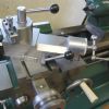
 520 forum posts 194 photos | Hi Ega, It is the back end of the split collet securing the tool block to the post !
This is a picture of my front tool block. You can see the head of the M6 cap screw that is used to tighten the split collet. The rear tool block is identical. In fact both were made to be interchangeable so that either could be used on the front or back. In fact the only thing that is missing on the rear one is a block for the adjuster screw to bear on. I have a loose block that I use. I keep promising myself that I will make a bracket to do the same job. I need a round toit !
|
| Nigel Bennett | 02/03/2021 11:20:23 |
 500 forum posts 31 photos | There was a bit of correspondence in ME back in the 1980s if I recall, where some chap made a rear toolpost out of a length of 2" square RHS with a central stud. Somebody made one like it and after a bit of a dig-in was looking somewhat askance at the smashed pieces of Tee slot that used to be part of his cross-slide. I think the same worry could be expressed about John Baron's toolpost; I don't think it would need much of a dig-in to rip it out of the tee-slot.
|
| ega | 02/03/2021 11:31:10 |
| 2805 forum posts 219 photos | John Baron: Thanks for your reply and photo. I may be having a senior moment but this was the feature I was interested in:
I'm guessing that it may be the adjuster screw head? I happily used a simpler version of your front tool post for many years, IIRC a Len Mason design from ME. |
| Hopper | 02/03/2021 11:31:58 |
 7881 forum posts 397 photos | Posted by larry phelan 1 on 02/03/2021 09:20:16:
I have a homemade toolpost using those blades, held in place with one long bolt from the cross slide and it works OK. Hopper, to pick your brains once again. The fingers on my steady have left hand threads, which I find confusing. Is there any good reason for this arrangement ? Can't think of one. Weird. |
| Hopper | 02/03/2021 11:36:18 |
7881 forum posts 397 photos | Posted by Nigel Bennett on 02/03/2021 11:20:23:
There was a bit of correspondence in ME back in the 1980s if I recall, where some chap made a rear toolpost out of a length of 2" square RHS with a central stud. Somebody made one like it and after a bit of a dig-in was looking somewhat askance at the smashed pieces of Tee slot that used to be part of his cross-slide. I think the same worry could be expressed about John Baron's toolpost; I don't think it would need much of a dig-in to rip it out of the tee-slot.
I think the problem there may be that the RHS was stood on end so the T nut in the slot was pulling the cast iron of the cross slide up into mid-air so there was nothing to stop it ripping a lump out of the T-slot. Like what can happen if you screw a clamping bolt on a milling machine table down into a T nut and let it bottom on the T slot and push the nut upwards. The single bolt rear toolpost in my pic above has been in use for over 50 years with no ill effect. Although, its base is a good 3" diameter or so, not just the same as the vertical round column. So I don't think its the single bolt that causes the problem. |
| ega | 02/03/2021 11:41:27 |
| 2805 forum posts 219 photos | The various personal styles of parting off were nicely illustrated in an ME cartoon where I think one of the characters suffered a catastrophic dig. Martin Cleeve, who worked his ML7 pretty hard, damaged his cross slide in the way suggested and replaced it with a steel version (I think actually produced at his request by Myford). Clearly, there is a balance to be struck between timidity and recklessness! |
| Alan Jackson | 02/03/2021 11:48:43 |
 276 forum posts 149 photos | Here is my rear toolpost. The base unit has a sloped surface which enables easy height setting without affecting rigidity and the two hold down bolts screw into a long tee nut in the tee slot.
Edited By Alan Jackson on 02/03/2021 11:52:49 Edited By Alan Jackson on 02/03/2021 11:53:32 Edited By Alan Jackson on 02/03/2021 11:55:04 |
| ega | 02/03/2021 12:11:04 |
| 2805 forum posts 219 photos | Posted by Hopper on 02/03/2021 11:36:18:
Posted by Nigel Bennett on 02/03/2021 11:20:23:
There was a bit of correspondence in ME back in the 1980s if I recall, where some chap made a rear toolpost out of a length of 2" square RHS with a central stud. Somebody made one like it and after a bit of a dig-in was looking somewhat askance at the smashed pieces of Tee slot that used to be part of his cross-slide. I think the same worry could be expressed about John Baron's toolpost; I don't think it would need much of a dig-in to rip it out of the tee-slot.
I think the problem there may be that the RHS was stood on end so the T nut in the slot was pulling the cast iron of the cross slide up into mid-air so there was nothing to stop it ripping a lump out of the T-slot. Like what can happen if you screw a clamping bolt on a milling machine table down into a T nut and let it bottom on the T slot and push the nut upwards. The single bolt rear toolpost in my pic above has been in use for over 50 years with no ill effect. Although, its base is a good 3" diameter or so, not just the same as the vertical round column. So I don't think its the single bolt that causes the problem. Assuming that the cross slide itself is flat then the mating surface of the base should be flat to match (and certainly not convex). I agree that a single bolt should then suffice and Myford's own early RTPs were made in this way. However, in practice, perfect mating may not be achieved and the additional fastenings provide some insurance against this. I suppose it may be permissible to scrape the base very slightly concave; the RHS design may have been an exaggerated and misguided attempt in this direction. |
| Hopper | 02/03/2021 12:17:41 |
7881 forum posts 397 photos | I am actually in the process of making a GH Thomas style rear toolpost for my ML7, much like the one David George shows above. It has two mounting bolts and tee nuts on the foot that sticks out. These go in the rear T slot and the vertical body of the toolpost sticks out the back of the cross slide. It looks to me, being used to my old single bolt type, that this type is more likely to pivot on the edge of the cross slide and pull lumps out of the T slot. But they have been in use since WW2 or so and seem to work ok. They just look "dicky" to me, perched out there in mid air. |
| bernard towers | 02/03/2021 12:23:40 |
| 1221 forum posts 161 photos | Hopper I thought that the two nuts on the foot went towards the operator, that’s what makes it so rigid! |
| John Baron | 02/03/2021 14:25:05 |
520 forum posts 194 photos | Posted by ega on 02/03/2021 11:31:10:
John Baron: Thanks for your reply and photo. I may be having a senior moment but this was the feature I was interested in:
I'm guessing that it may be the adjuster screw head? I happily used a simpler version of your front tool post for many years, IIRC a Len Mason design from ME. Yes you are right it is the height adjustment screw. I mistakenly thought that you were referring to the split clamp. I think it must be me having the senior moment, now that I've re re read your original question. Sorry !!!
Edited By John Baron on 02/03/2021 14:40:31 |
| John Baron | 02/03/2021 14:32:07 |
520 forum posts 194 photos | Posted by Nigel Bennett on 02/03/2021 11:20:23:
There was a bit of correspondence in ME back in the 1980s if I recall, where some chap made a rear toolpost out of a length of 2" square RHS with a central stud. Somebody made one like it and after a bit of a dig-in was looking somewhat askance at the smashed pieces of Tee slot that used to be part of his cross-slide. I think the same worry could be expressed about John Baron's toolpost; I don't think it would need much of a dig-in to rip it out of the tee-slot.
Hi Nigel, Yes I agree that there is that risk ! However I've very rarely parted off anything more than an inch in diameter, much preferring to use the bandsaw. However I did start to make a base piece to go around the column and fasten to the "T" slot in front of it. Another one of those round toit's
|
| John Baron | 02/03/2021 14:35:24 |
520 forum posts 194 photos | Posted by bernard towers on 02/03/2021 12:23:40:
Hopper I thought that the two nuts on the foot went towards the operator, that’s what makes it so rigid! +1
|
| mechman48 | 02/03/2021 14:48:53 |
 2947 forum posts 468 photos | I made mine from the Hemmingway kit; one side has an angled slot , but I found that this created too much overhang & altering it moved the centre height out of position so I used the horizontal slotted side with a different holder which allows me to alter the over hang without losing centre height..
Leaving the centre height as shown produces too much over hang..
George. |
| Howard Lewis | 02/03/2021 15:58:52 |
| 7227 forum posts 21 photos | When I had a ML7, I made a back toolpost from a piece of 2" box section, and welded gauge plate onto it to make the platforms. From memory, it located to the Cross Slide by having dowels in the base which were a snug fit in the T slot. For my present lathe, I made a four way indexing back toolpost. This locates to the Cross Slide by two 1/4" dowels which bear against the back of the Cross Slide. It is secured by a long T nut with two M8 studs tapped and peened into the long T nut. (IF I could find pictures of it, I would paste into an album, but can't ) So you have two methods of locating a back tool post to prevent it rotating. Not sure if you need such a large securing stud. A 1/4 BSF stud was quite sufficient to crack a Cross Slide on the ML7! So a single M8 stud into a t Nut and two dowels should be quite sufficient. PS I run my parting tool with no Top Rake. to reduce the risk of dig ins! makes keepingbthe tool on centre height much easier. Howard Edited By Howard Lewis on 02/03/2021 16:01:07 |
| ega | 02/03/2021 15:59:29 |
| 2805 forum posts 219 photos | Posted by Hopper on 02/03/2021 12:17:41:
I am actually in the process of making a GH Thomas style rear toolpost for my ML7, much like the one David George shows above. It has two mounting bolts and tee nuts on the foot that sticks out. These go in the rear T slot and the vertical body of the toolpost sticks out the back of the cross slide. It looks to me, being used to my old single bolt type, that this type is more likely to pivot on the edge of the cross slide and pull lumps out of the T slot. But they have been in use since WW2 or so and seem to work ok. They just look "dicky" to me, perched out there in mid air. I agree with you about the look of the overhung toolpost. However, it is worth remembering that GHT's design was probably based on Ian Bradley's earlier work. IB's design for the Drummond was I believe overhung. The explanation for why the design works in practice may be in the following point from his Amateur's Workshop: "the attachment [is] secured to the cross slide by two T-slot [bolts] located directly under the cutting point of the tool. The location of these T- slot bolts is an essential feature of the design. The placing of them directly under the tool point is intended to overcome the tipping strain imposed on the attachment when in operation". The longer cross slide of the Super7 does, of course, permit the third fastening passing through the main body of the RTP. |
| ega | 02/03/2021 16:04:04 |
| 2805 forum posts 219 photos | Mechman48: Your last photo shows the angled slot; is the angle actually more than the 7 degrees in the original GHT design? |
| mechman48 | 02/03/2021 16:39:19 |
2947 forum posts 468 photos | It was made to the drawing supplied with kit & as I recall it was 7*. It may not look it on the pic but it was propped up at the rear so there's probably some parallax error in there... George. |
| Peter Greene | 02/03/2021 17:04:05 |
| 865 forum posts 12 photos | Posted by Hopper on 02/03/2021 07:49:13:
Alignment is achieved by two round studs in the base that fit into the T slot. Just drill and ream two holes and loctite a couple of pins in there, Or tap and thread etc. You can make the pins oversize and file the final fit to get exact alignment if you like. Pins go one each side of the centre bolt. Been in use for more than 50 years that I know of and works well. Good idea, Hopper. Better than mine for an existing part! |


.jpg")

Please login to post a reply.
Magazine Locator
Want the latest issue of Model Engineer or Model Engineers' Workshop? Use our magazine locator links to find your nearest stockist!
Sign up to our Newsletter
Sign up to our newsletter and get a free digital issue.
You can unsubscribe at anytime. View our privacy policy at www.mortons.co.uk/privacy
Latest Forum Posts
- hemingway ball turner
04/07/2025 14:40:26 - *Oct 2023: FORUM MIGRATION TIMELINE*
05/10/2023 07:57:11 - Making ER11 collet chuck
05/10/2023 07:56:24 - What did you do today? 2023
05/10/2023 07:25:01 - Orrery
05/10/2023 06:00:41 - Wera hand-tools
05/10/2023 05:47:07 - New member
05/10/2023 04:40:11 - Problems with external pot on at1 vfd
05/10/2023 00:06:32 - Drain plug
04/10/2023 23:36:17 - digi phase converter for 10 machines.....
04/10/2023 23:13:48 - More Latest Posts...
- View All Topics
Support Our Partners


Shopping Partners
Subscription Offer

Latest "For Sale" Ads
- Reeves** - Rebuilt Royal Scot by Martin Evans
by John Broughton
£300.00 - BRITANNIA 5" GAUGE James Perrier
by Jon Seabright 1
£2,500.00 - Drill Grinder - for restoration
by Nigel Graham 2
£0.00 - WARCO WM18 MILLING MACHINE
by Alex Chudley
£1,200.00 - MYFORD SUPER 7 LATHE
by Alex Chudley
£2,000.00 - More "For Sale" Ads...
Latest "Wanted" Ads
- D1-3 backplate
by Michael Horley
Price Not Specified - fixed steady for a Colchester bantam mark1 800
by George Jervis
Price Not Specified - lbsc pansy
by JACK SIDEBOTHAM
Price Not Specified - Pratt Burnerd multifit chuck key.
by Tim Riome
Price Not Specified - BANDSAW BLADE WELDER
by HUGH
Price Not Specified - More "Wanted" Ads...
Get In Touch!
Do you want to contact the Model Engineer and Model Engineers' Workshop team?
You can contact us by phone, mail or email about the magazines including becoming a contributor, submitting reader's letters or making queries about articles. You can also get in touch about this website, advertising or other general issues.
Click THIS LINK for full contact details.
For subscription issues please see THIS LINK.
Digital Back Issues


Donate

 Register
 Log-in
Model Engineer Magazine
- Percival Marshall
- M.E. History
- LittleLEC
- M.E. Clock

ME Workshop
- An Adcock
- & Shipley
- Horizontal
- Mill

Subscribe Now
- Great savings
- Delivered to your door

Pre-order your copy!
- Delivered to your doorstep!
- Free UK delivery!
All Forum Topics > Workshop Tools and Tooling > Home Made Rear Toolpost Issue